Note : Les descriptions sont présentées dans la langue officielle dans laquelle elles ont été soumises.
CA 02495848 2005-02-02
SP 23023 VD
1
ROTOR DISK BALANCING DEVICE, DISK FITTED WITH SUCH A
DEVICE AND ROTOR WITH SUCH A DISK
DESCRIPTION
TECHNICAL DOMAIN
This invention relates to the technical domain
of turbomachine rotors.
It is particularly applicable to a rotor disk
balancing device. It is also applicable to a rotor disk
equipped with such a device and a rotor equipped with
such a disk.
STATE OF PRIOR ART
US patent 3 888 601 describes a turbomachine
fitted with a balancing device. It discloses a rotor
disk provided with mobile blades around its periphery.
Each mobile blade is fitted with an airfoil, a root and
a platform located between the airfoil and the root.
The disk comprises grooves around its periphery
arranged along an axial direction in which the root of
a blade will be fitted. When a blade is installed on
the disk, its platform projects laterally on each side
of the disk. Hooks formed in a single piece with the
disk are arranged circumferentially on one side of the
disk, at a spacing from each other. They comprise two
opposite sidewalls arranged radially in coplanar
alignment with the sidewalk of the blade assembly
grooves. The disk or the rotor is balanced using
balancing masses comprising a principal body and two
tabs opposite each other, and each of which will be
inserted between the two arms of a hook. According to
CA 02495848 2005-02-02
SP 23023 VD
2
this document, the blades are inserted in their
corresponding grooves in the disk. Each balancing mass
is then inserted so as to insert its tabs into a hook
in the disk, making it slide in contact with the disk
outwards along a radial direction, until it stops in
contact with a blade platform. The balancing masses
thus installed are then immobilized; they cannot move
in the axial direction because their tabs are held in
place in a hook, their outwards radial displacement is
prevented by the platform that acts as a stop, and
their inwards radial displacement is prevented by an
elastic retaining ring placed in contact with the
corresponding face of the disk. When balancing masses
have to be replaced, the elastic retaining ring is
withdrawn, the masses are withdrawn and new masses are
installed to replace them.
The balancing device that has just been
described has a disadvantage in that it is not suitable
for a rotor disk of the integrally bladed disk type. It
has another disadvantage in that this arrangement of
disk balancing masses considerably increases the
dimension of the disk in the axial direction. The
thickness of the hooks, the dimension of the masses and
of the platforms above them, all add to the axial
dimension of the disk. Furthermore, if there is a set
of several disks, the dimension of the turbomachine
along the axial direction may become excessive.
US patent. 4 848 182 and US patent 4 926 ?10
describe a balancing method and a system for a
multidisk rotor with integral blade assembly. A
balancing ring is fixed by shrinking onto a disk, such
CA 02495848 2005-02-02
SP 23023 'YD
3
that its peripheral surface is in contact with a
contact face of the disk on one side of the disk and is
oriented radially inwards into the disk. The ring is
stopped laterally in contact with the inside of the
S disk against a lip of the disk that extends radially
outwards from the contact face. It is held laterally in
place outwards from the disk by means of an elastic
retaining_ring. The ring comprises teeth around its
outer periphery extending radially outwards, and that
are separated by openings. When the ring is fixed on
the disk, its teeth are in contact with the contact
face of the disk. Consequently, the openings form
cavities with the contact face and the lip of the disk,
distributed around the circumference and opening
laterally towards the outside of the disk. Several
disks each equipped with their balancing ring are
assembled together to form the rotor. The disk or rotor
balancing process consists of inserting balancing
masses in some of the cavities that are distributed
around the circumference. The balancing masses are held
in place laterally outwards from the disk by the
elasti-c retaining ring, to prevent them from coming out
of their cavity.
The balancing device that has just been
described has a disadvantage in that the balancing
masses are installed on a balancing ring. This requires
the presence of a ring and an attachment operation by
shrinking of its balancing ring on the disk.
PRESENTATION OF TI3E INVENTION
One purpose of this invention is to provide a
balancing device for a disk and/or a rotor using
CA 02495848 2005-02-02
SP X3023 VD
4
balancing masses, which does not have the disadvantages
of prior art described above.
According to a first aspect, the invention
relates to a balancing device that is preferably
applicable to a rotor disk of the integrally bladed
type, the disk being provided with a rim. It comprises
housings formed in said rim and balancing masses housed
in said housings.,
Preferably, these housings are located in a
side face of the rim, under a platform of the disk that
supports the blades, and are distributed around the
circumference of the rim.
According to a first embodiment, the housings
do not pass through the rim and are in the form of
blind holes, with an orifice opening up onto a side
face of the rim. According to a second embodiment,
these housings pass through the rim and their orifices
open up on first and second opposite lateral faces of
the rim.
The shape of the housings and the masses is
adapted to prevent a rotation or tipping of each mass
in its corresponding housing.
The balancing device also comprises one or two
spring retaining rings, designed to be positioned
laterally against the rim, so as to at least partially
close off the corresponding orifices of the housings.
According to one variant, the spring retaining ring
closes off at least half of the orifices. According to
another variant, the spring retaining ring completely
closes off the orifices. The spring retaining ring
CA 02495848 2005-02-02
sP 23o2s vD
comprises at least one protuberance that fits into one
of the housings, so that it does not rotate axially.
According to one variant, the balancing device
comprises one or two circumferential slits formed under
5 the platform into which a peripheral edge of a spring
retaining ring will be fitted.
According to a second aspect, the invention
relates to an Integrally bladed rotor disk, that is
equipped with a balancing device according to the first
aspect of the invention.
According to a third aspect, the invention
relates to a rotor, that comprises at least one disk
according to the second aspect of the invention.
One advantage of the balancing device according
to the invention lies in the fact that the mass
housings form an integral part of the rim, which avoids
the need for an additional part in which the balancing
masses will fit. The result is a reduction of
manufacturing costs and the rotor assembly time.
Another advantage of the balancing system
according to the invention lies in the fact that the
masses thus placed are easily accessible, and that it
is possible to modify balancing of the disks or the
rotor by modifying the distribution of balancing masses
without the need to disassemble the rotor entirely.
Another advantage lies in the fact that with
such a balancing device, it is possible to improve the
correction of rotor out of balances.
BRIEF DESCRIPTION OF THE FIGURES
The invention will be better understood after
reading the following detailed description of
CA 02495848 2005-02-02
S P 2 3 02 3 'VD
6
particular embodiments of the invention provided for
illustration and that are in no way limitative, with
reference to the appended drawings, wherein:
- Figure 1 is a partial representation of an
axial section of a rotor that comprises integrally
bladed disks and disks with removable blades;
- Figure 2 is a partial representation of an
axial. section of a disk provided with a first
embodiment of the balancing device according to the
invention;
- Figure 8 is similar to figure 2, with another
axial section;
- Figure 4 is a partial representation of a
perspective view of a disk fitted with the balancing
device according to the invention;
- Figure 5 is a partial front view of a first
embodiment of the balancing device according to the
invention;
- Figure ~ is similar to figure 3, for a second
embodiment of the balancing device according to the
invention.
DETAILED PRESENTATION OF PARTICULAR EMBODIMENTS
Firstly with reference to figure 1, the figure
generally shows a rotor 10 comprising six disks 12, 14.
In the example illustrated, three of the disks (at the
right in the figure) are disks 12 each with removable
blades 16 fixed t.o the rim 18 of the disk. The other
three disks (at the left in the figure) are integrally
bladed disks 14, each with blades 20 being made
integral with the rim 18 of the disk.
CA 02495848 2005-02-02
~P 23023 VD
7
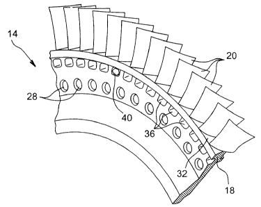
Figures 2 to 4 illustrate an integrally bladed
disk 14 comprising a rim 18 and blades 20 made integral
with the rim 18. Figure 2 shows a connection flange 24
that will be used to assemble the disk 14 with an
adjacent disk (not shown) fixed to the disk 14 by
attachment means for example such as screws passing
through a drilling 26 in the rim and a drilling 28 in
the connection flange 24.
The rim 18 is a thicker area, in which a face
oriented radially outwards acts as platform 32 from
which the blades 20 extend radially outwards.
Housings 36 are formed in the rim 18, and more
particularly under the platform 32, and are distributed
circumferentially around the rim 18. According to a
first embodiment of the balancing device according to
the invention, these housings 36 are in the form of
blind holes opening up on a single side face 180 of the
rim 18.
The disk and/or the rotor are balanced by
placing balancing masses 40 in the housings 36. A mass
40 is placed in some housings 36, and no balancing mass
is placed in other housings 36, depending on the need
that becomes apparent during the balancing process.
In the example illustrated, the housings 36
have an approximately rectangular section with rounded
corners, in the axial plane and/or the transverse
plane. The balancing masses 40 are approximately in the
shape of a rectangular parallelepiped, with dimensions
corresponding to the dimensions of the housing 36, such
that each balancing mass 40 fits into its housing 36
without it being able to rotate within it. Preferably,
CA 02495848 2005-02-02
SP 23023 VD
8
the edges of the rectangular parallelepiped are cut so
as to form additional edges on the balancing mass 40,
in order to further limit any rotation or tipping
movements of the balancing mass 40 in its housing 36.
Preferably, the area of the rim 18 located
between the platform 32 and the housings 36 overhangs
slightly above the housings 36. In this overhanging
part that projects laterally beyond the rim 18 over the
housings 36, the rim 18 is provided with a
circumferential slit 42 that is arranged in one face
substantially opposite the platform 32 and that runs
along the housings 36.
A spring retaining ring 44 is located in the
slit 42, with a width such that it at least partially
closes off the housings 36 so as to hold the balancing
masses 40 in place.
Preferably, the spring retaining ring 44 is cut
transversally so that it can be easily installed and
removed.
Preferably, the spring retaining ring 44 is
provided with an anti-rotation member 46 to prevent it
from rotating in the transverse plane when it is
installed in the slit 42 of the rim 18. This anti-
rotation member is for example materialized by a
protrusion 46 on the retaining ring 44 that is inserted
into one of the housings 36 when it is not occupied by
a balancing mass 40 (figure 3).
Figure 5 illustrates a front and partially
enlarged view of a housing 36. In the example
illustrated, the spring retaining ring 44 closes off
approximately half of the housings 36. It would be
CA 02495848 2005-02-02
SP 23023 VD
9
possible for the spring retaining ring 44 to close off
two thirds of the housings 36, or all housings 36. To
prevent the balancing masses 40 from being able to exit
from the housings 36, it is preferred that the spring
retaining ring covers at least half of the housings 36.
According to another variant embodiment, the
balancing masses 40 can also be fixed in the housings
w 36 by providing a small quantity of adhesive at the
bottom of the housing before installing the balancing
mass 40 in the housing, to guarantee that the balancing
masses 40 will not come out of their housings 36.
According to a second embodiment of the
balancing device according to the invention illustrated
in figure 6, the housings 38 are in the form of through
holes that open up on each side of the rim 18.
Preferably, these housings 38 are provided with a first
cavity 382 similar to the housings 36 in the first
embodiment and that open up on a first side face 182 of
the rim 18. They also have a second cavity 384
approximately symmetrical to the first cavity 382 with
respect to a median plane of the rim 18 and that opens
up on a second side face 184 of the rim 18, opposite
the first side face 182 of the rim. The two cavities
382, 384 are connected to each other by an intermediate
channel 386 that; in the example illustrated, has a
smaller cross section than the corresponding sections
of the two cavities 382, 384.
The disk and/or the rotor are balanced in a
similar manner to the balancing done with the first
embodiment of the balancing device, described above.
Consequently, the balancing masses 40 are placed in
CA 02495848 2005-02-02
SP 23023 VD
some of the first cavities 382, and a first spring
retaining ring 442 is installed in a first slit 422
formed in a first part overhanging the first face 182
of the rim 18, so as to at least partially close off
5 the first cavities 382 and to hold the balancing masses
40 in place.
The disk and/or the rotor could be balanced
even more precisely by placing additional balancing
masses 30 in some of the intermediate channels 386.
10 These additional balancing masses, shown in dashed
lines in figure 6, have a shape similar to the shape of
the balancing masses 40, and dimensions adapted to the
dimensions of the intermediate channels 386.
Still according to the second embodiment,
sealing flanges 48 are provided to make the disk 14
leak tight. Preferably, they are placed at the bottom
of the second cavities 384, and prevent any
communication between the second cavities and the
smaller intermediate channels 386. A second spring
retaining ring 444 is installed in a second slit 424
formed in a second part overhanging the second face 184
of the rim 18, so as to at least partially close off
the second cavities 384 and to hold the sealing flanges
48 in position.
The first spring retaining ring 442 and the
second spring retaining ring 444, are preferably cut
transversally so that they can be easily installed and
removed.
The first spring retaining ring 442, and the
second spring retaining ring 444, are preferably
provided with an anti-rotation member (not shown),
CA 02495848 2005-02-02
SP 23023 VD
11
similar to the anti-rotation member on the spring
retaining ring 44 according to the first embodiment of
the device.
Closing off the housings 36 by the spring
retaining ring 44 described with reference to figure 5
for the first embodiment of the balancing device is
equally applicable to the second embodiment of the
balancing device.
The invention that has just been described is
not limited to the embodiments that have been described
above. It is possible to make improvements and
modification to these embodiments within the
capabilities of those skilled in the art, without
departing from the scope of the invention.