Sélection de la langue

Search

Sommaire du brevet 2498110 

Énoncé de désistement de responsabilité concernant l'information provenant de tiers

Une partie des informations de ce site Web a été fournie par des sources externes. Le gouvernement du Canada n'assume aucune responsabilité concernant la précision, l'actualité ou la fiabilité des informations fournies par les sources externes. Les utilisateurs qui désirent employer cette information devraient consulter directement la source des informations. Le contenu fourni par les sources externes n'est pas assujetti aux exigences sur les langues officielles, la protection des renseignements personnels et l'accessibilité.

Disponibilité de l'Abrégé et des Revendications

L'apparition de différences dans le texte et l'image des Revendications et de l'Abrégé dépend du moment auquel le document est publié. Les textes des Revendications et de l'Abrégé sont affichés :

  • lorsque la demande peut être examinée par le public;
  • lorsque le brevet est émis (délivrance).
(12) Brevet: (11) CA 2498110
(54) Titre français: CHUTE D'EAU A MINCE FILET POUR INSTALLATION THERMALE
(54) Titre anglais: TRICKLE WATERFALL FOR SPA
Statut: Réputé périmé
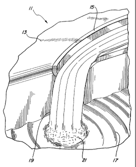
Données bibliographiques
(51) Classification internationale des brevets (CIB):
  • A47K 3/00 (2006.01)
  • A61H 33/00 (2006.01)
  • E04H 4/00 (2006.01)
(72) Inventeurs :
  • KUNKEL, RICHARD (Etats-Unis d'Amérique)
(73) Titulaires :
  • WATKINS MANUFACTURING CORPORATION (Etats-Unis d'Amérique)
(71) Demandeurs :
  • WATKINS MANUFACTURING CORPORATION (Etats-Unis d'Amérique)
(74) Agent: PIASETZKI NENNIGER KVAS LLP
(74) Co-agent:
(45) Délivré: 2009-05-12
(22) Date de dépôt: 2005-02-23
(41) Mise à la disponibilité du public: 2005-10-21
Requête d'examen: 2006-09-14
Licence disponible: S.O.
(25) Langue des documents déposés: Anglais

Traité de coopération en matière de brevets (PCT): Non

(30) Données de priorité de la demande:
Numéro de la demande Pays / territoire Date
10/828,905 Etats-Unis d'Amérique 2004-04-21

Abrégés

Abrégé français

Une chute d'eau pour installation thermale ne prenant aucune place assise sur le rebord supérieur de l'installation thermale. L'eau provenant du système de circulation de l'installation thermale circule dans un canal à extrémité fermée dans le rebord supérieur et le long du canal vers l'extrémité ouverte située sur le bord du rebord supérieur de la paroi intérieure et tombe dans l'eau dans l'installation thermale. Une source lumineuse là où l'eau pénètre dans le canal à extrémité fermée, pouvant être ajustée pour changer de couleur, envoie un faisceau lumineux dans la chute d'eau, illuminant l'eau qui tombe dans l'installation thermale, en différentes couleurs, selon ses préférences.


Abrégé anglais

A waterfall for a portable spa does not take up any seat space by being set into the top rim of the spa. Water from the spa circulation system flows into a closed end of a channel located in the top rim and along the channel to the open end located at the edge of the top rim on the inside wall to fall into the body of water in the spa. A light source at the point where the water enters the closed end of the channel, which may be adapted to change colors, directs light into the water flow, lighting the water that falls into the spa, in different colors, as desired.

Revendications

Note : Les revendications sont présentées dans la langue officielle dans laquelle elles ont été soumises.


CLAIMS:

1. In combination with a spa with a circulating system and a top rim having an

outside and inside edge, the improvement being a waterfall structure
comprising:
an open water flow channel having a channel floor, side walls, a first end
that is
closed and a second end that is open, the side walls being longer than the
ends, the ends
being no longer than the distance between the outside and inside edge of the
top rim of the
spa, the channel being embedded in the top rim of the spa with the side walls
of the water
flow channel being between the outside and inside edge of the top rim of the
spa, and the
second open end of the water flow channel located at the inside edge of the
top rim of the
spa; and
a water access aperture in the channel floor of the open water flow channel at
the
closed end, allowing water to flow into the channel, at the closed end, and
along the
channel to the open end, spilling over the inside edge of the top rim into the
spa.


2. The waterfall structure of claim 1, wherein the water flow channel has an
aperture
in the channel floor at the first end of the channel, and further comprising:
a light transmitting lens in the floor of the channel, covering the aperture
whereby
water from the water access aperture flowing into the channel passes over the
lens and
picks up light energy passing through it.


3. The waterfall structure of claim 2 further comprising:
a plurality of flow ribs located on the channel floor for guiding the water
flow in a
laminar manner along the length of the channel.


4. The waterfall structure of claim 3 further comprising:
a disruptor button having a height and a circumference, located at the second
end
of the channel for disturbing the laminar water flow as it exits the channel
and spills into
the spa.


5. The waterfall structure of claim 2 further comprising:
a cap, having a front and back, with a skirt around the back, the cap located
over

8


the water access aperture in the channel floor, at the first end, directing
water from the
access aperture in the floor of the channel to flow over the lens.


6. The waterfall structure of claim 4, wherein all the parts of the waterfall
structure
are made of plastic.


7. The waterfall structure of claim 6, wherein water from the circulating
system of the
spa is supplied to the water access aperture of the waterfall structure.


8. The waterfall structure of claim 5, wherein the lens floor seals the
aperture in the
channel floor.


9

Description

Note : Les descriptions sont présentées dans la langue officielle dans laquelle elles ont été soumises.


CA 02498110 2005-02-23

TRICKLE WATERFALL FOR SPA
BACKGROUND OF THE INVENTION
1. Field of the Invention.

[00011
The present invention relates generally to improvements in portable spas,
and more particularly, pertains to new and improved water features for a
portable spa wherein a waterfall is provided as part of the portable spa for
the
enjoyment and entertainment of the spa users.

2. Description of Related Art.
[0002]

In the field of portable spas, manufacturers are continually trying to
enhance the portable spa product by adding various entertainment features to
it
beyond the hot water and jet massaging functions. Manufacturers have added
audio systems to a portable spa device. Some manufacturers have added water
features, such as waterfalls, to portable spa devices. The problem associated
with the inclusion of a waterfall in a portable spa is the amount of space
required by the waterfall. The present invention overcomes this problem.

SUMMARY OF THE INVENTION
[0003]

A channel with a closed end and an open end is set into the top rim of a
portable spa with the open end of the channel located at the edge of the top
rim
1


CA 02498110 2005-02-23

on the inside wall. Water is fed into the channel at the closed end so that it
flows over a light source, picking up light energy. The water flows in laminar
fashion along the channel embedded in the top rim guided by flow ribs located
along the channel floor. A disruptor button on the channel floor at the open
end
disturbs the laminar flow, causing the light in the water flow to be reflected
and
become more visible as it falls into the main water body in the spa.

BRIEF DESCRIPTION OF THE DRAWINGS
[0004]

The objects and advantages of the present invention will become readily
apparent upon consideration of the following detailed description in
conjunction
with the accompanying drawings in which like reference numerals designate
like parts throughout the figures thereof and wherein:

[0005]
Figure 1 is a perspective illustration of a preferred embodiment of the
present invention.

[0006]
Figure 2 is an assembly drawing of the waterfall of Figure 1.
[0007l

Figure 3 is a top perspective of the channel of the waterfall of Figure 1.
[000g]

Figure 4 is a top plan view of the channel of Figure 3.
2


CA 02498110 2005-02-23
[0009]

Figure 5 is a cross-section taken along line 5-5 of Figure 4 looking in the
direction of the arrows.

[0010]
Figure 6 is a top and bottom perspective of a top cap for the waterfall of
Figure 1.

[0011]
Figure 7 is a perspective of the lens used in the channel of the waterfall of
Figure 1.

[0012]
DETAILED DESCRIPTION OF THE PREFERRED EMBODIMENTS
[0013]

The waterfall feature 11 of the present invention, as seen in Figure 1, is
located in the top rim 13 of the portable spa with the water flow channel 15
embedded in the top rim 13 of the spa. Water 19 falls from the channel 15 at
the inside edge of the spa rim into the main water body 17 of the spa with a
splash 21, causing light reflection from the flow and the splash, if the water
flow 19 is lighted in a manner hereinafter described.

[0014]
Figure 2 illustrates the basic parts of a preferred embodiment of the
present invention. The channel 15 of the waterfall is shown as having an open

3


CA 02498110 2008-04-18

end 39 and a closed end 47 with walls 41 defining a channel of flow for water
entering channel 15 at an access aperture 33 in a platform 31 at the closed
end
47 of channel 15. Aperture 33 connects to a threaded coupling 25 on which a
pipe coupling nut 27 may be threaded to connect the aperture 33 to the water
circulation system of the portable spa.

[0015]
The bottom 34 of channel 15 has a plurality of ribs 35 extending from the
closed end 47 to the open end 39. The water flow entering at aperture 33 at
the
closed end 47 flows towards the open end 39 in a quiet laminar manner because
of the ribs 35. A disruptor button 37 located at the open end 39 of channel 15
disturbs the water flow at the open end 39 just before the water spills over
lip 43
of channel 15 into the main body of water of the portable spa (not shown). The
disruptor button 37 creates enough turbulence in the water flow at that point
to
cause the light energy in the water to be reflected out of the water flow and
thereby become more visible to the human eye.

[0016]
A cap 23 of unique construction, as will be explained hereinafter, with a
skirt 49 around its back side snaps onto studs 55 over aperture 33 on the
platform 31, thereby forming an inlet chamber 30 having a directional opening
that directs the water flow towards the open end 39 of channel 15. An aperture
45
located in the platform 31 and bottom 34 of channel 15 is closed by a lens
ramp
29 constructed in a manner as will be described hereinafter. The lens 29 is
4


CA 02498110 2008-04-18

located at the flow output of the inlet chamber so that the flow is over the
lens
and light from the other side of the lens is injected into the water flow, as
it
leaves the inlet chamber. The light source (not shown) may be of any
convenient structure. The use of CFD's of various colors, however, is
particularly suited for this application.

[0017]
Figure 3 illustrates more clearly the channel wall structure 40 and 41 and
floor 34 of the channel 15 that guides the water between the closed end 47 and
the open end 39. It should be remembered that this entire structure is located
in
the top rim a portable spa. The upper walls are preferably flush with the top
rim.
The platform 31 at the closed end 47 of the channel is raised above the floor
34
of the channel 15 so as to create a drop in height between the platform 31 and
the floor 34. An aperture 45 is located between the platform level 31 and
floor
34 in the flow path. The aperture is filled by a lens ramp 29 of a
construction as
will hereinafter be described. The water that comes in the chamber at aperture
33 in platform 31 gets accelerated slightly when it flows down the incline
formed by the lens ramp 29 in aperture 45. Besides accelerating slightly, the
water flow picks up light energy passing through the lens from the other side.
[0018]

As can be seen in Figure 4, the shape of the channel 15 is unique in that
the wall 41 at the inside water edge of the top rim is thicker and straight,
while
the wall 40 at the outside edge of the top rim is curved. This shape provides
a


CA 02498110 2008-04-18

very aesthetically pleasing water flow channel that fits within the confines
of
the top rim of the portable spa.

[0019]
As can be seen in Figure 5, the threaded stud 25 empties directly into the
aperture 33 in platform 31. Located in aperture 33 is a plurality of water
flow
guides 36 which tend to quiet the turbulent flow entering attachment stud 25,
into more laminar flow that exits aperture 33 and fills the chamber above
platform 31 before flowing down lens ramp 29, picking up light energy on its
way.

[0020]
Figure 6 illustrates in greater detail the cap 23 which fits over the
aperture 33 in the raised platform 31 at the closed end of flow channel 15.
Cap
23 has a skirt 49 that extends around the perimeter, except for a short
distance
of the perimeter, which allows water to flow out of the chamber. The skirt 49
has a pair of columns with apertures 51 and 53 therein, respectively, that fit
into
studs 57 and 55 (Figure 3). The skirt 49 of the cap 23 is glued to the
platform
31, thereby creating a chamber which has only one egress for the water
entering
at aperture 33 in platform 31.

[0021]
The lens ramp 29 which fits into aperture 30 of the water flow channel is
built to have a ledge 65 at its concave back side, a ledge 61 at its convex
front
side, and ledges 67 between the front and back sides, so that the ramp easily
6


CA 02498110 2008-04-18

snaps into the aperture and is glued by way of these ledges to the material
surrounding aperture 30 in channel 15. The lens ramp 29 has a flat portion 63
at the
top which conforms with platform 31, and a sloping portion 59 through which
light
is transmitted to water flowing down the surface of the sloping portion to the
bottom 34 of channel 15, thereby providing a smooth flow path for the water
from
the chamber above platform 31 into the flow channel 15.

7

Dessin représentatif
Une figure unique qui représente un dessin illustrant l'invention.
États administratifs

Pour une meilleure compréhension de l'état de la demande ou brevet qui figure sur cette page, la rubrique Mise en garde , et les descriptions de Brevet , États administratifs , Taxes périodiques et Historique des paiements devraient être consultées.

États administratifs

Titre Date
Date de délivrance prévu 2009-05-12
(22) Dépôt 2005-02-23
(41) Mise à la disponibilité du public 2005-10-21
Requête d'examen 2006-09-14
(45) Délivré 2009-05-12
Réputé périmé 2016-02-23

Historique d'abandonnement

Il n'y a pas d'historique d'abandonnement

Historique des paiements

Type de taxes Anniversaire Échéance Montant payé Date payée
Enregistrement de documents 100,00 $ 2005-02-23
Le dépôt d'une demande de brevet 400,00 $ 2005-02-23
Requête d'examen 800,00 $ 2006-09-14
Taxe de maintien en état - Demande - nouvelle loi 2 2007-02-23 100,00 $ 2006-12-20
Taxe de maintien en état - Demande - nouvelle loi 3 2008-02-25 100,00 $ 2007-12-21
Taxe de maintien en état - Demande - nouvelle loi 4 2009-02-23 100,00 $ 2008-12-22
Taxe finale 300,00 $ 2009-02-18
Taxe de maintien en état - brevet - nouvelle loi 5 2010-02-23 200,00 $ 2010-01-07
Taxe de maintien en état - brevet - nouvelle loi 6 2011-02-23 200,00 $ 2011-01-25
Taxe de maintien en état - brevet - nouvelle loi 7 2012-02-23 200,00 $ 2012-01-19
Taxe de maintien en état - brevet - nouvelle loi 8 2013-02-25 200,00 $ 2013-01-18
Taxe de maintien en état - brevet - nouvelle loi 9 2014-02-24 200,00 $ 2014-01-22
Titulaires au dossier

Les titulaires actuels et antérieures au dossier sont affichés en ordre alphabétique.

Titulaires actuels au dossier
WATKINS MANUFACTURING CORPORATION
Titulaires antérieures au dossier
KUNKEL, RICHARD
Les propriétaires antérieurs qui ne figurent pas dans la liste des « Propriétaires au dossier » apparaîtront dans d'autres documents au dossier.
Documents

Pour visionner les fichiers sélectionnés, entrer le code reCAPTCHA :


Pour visualiser une image, cliquer sur un lien dans la colonne description du document. Pour télécharger l'image (les images), cliquer l'une ou plusieurs cases à cocher dans la première colonne et ensuite cliquer sur le bouton "Télécharger sélection en format PDF (archive Zip)" ou le bouton "Télécharger sélection (en un fichier PDF fusionné)".

Liste des documents de brevet publiés et non publiés sur la BDBC .

Si vous avez des difficultés à accéder au contenu, veuillez communiquer avec le Centre de services à la clientèle au 1-866-997-1936, ou envoyer un courriel au Centre de service à la clientèle de l'OPIC.


Description du
Document 
Date
(yyyy-mm-dd) 
Nombre de pages   Taille de l'image (Ko) 
Abrégé 2005-02-23 1 16
Description 2005-02-23 7 208
Revendications 2005-02-23 2 45
Dessins 2005-02-23 4 104
Dessins représentatifs 2005-09-23 1 17
Page couverture 2005-10-06 1 43
Dessins 2008-04-18 4 103
Revendications 2008-04-18 2 56
Description 2008-04-18 7 209
Dessins représentatifs 2009-04-22 1 19
Page couverture 2009-04-22 2 49
Cession 2005-02-23 7 223
Poursuite-Amendment 2006-09-14 1 28
Poursuite-Amendment 2006-11-02 1 39
Poursuite-Amendment 2007-10-31 2 66
Poursuite-Amendment 2008-04-18 12 403
Correspondance 2009-02-18 1 32
Correspondance 2009-11-27 2 56
Correspondance 2009-12-14 1 14
Correspondance 2009-12-14 1 17
Correspondance 2014-03-19 5 176
Correspondance 2014-09-24 1 22
Correspondance 2014-09-24 1 26
Correspondance 2014-02-24 3 50
Correspondance 2014-07-16 4 96