Note : Les descriptions sont présentées dans la langue officielle dans laquelle elles ont été soumises.
CA 02498114 2005-03-08
WO 2004/024574 PCT/CA2003/001187
1
RECLOSABLE METAL BEVERAGE CAN
Background of the Invention
1. Technical Field
This invention relates to thin wall metal beverage
cans, and in particular to aluminum beverage cans having
a threaded neck portion for receiving a threaded closure
cap to seal the contents of the container.
2. Background Art
Aluminum cans are now wi.dely used in the packaging
of beer, soft drinks, etc. and these are typically
adapted to be closed with relatively flat lids or ends.
Although the standard aluminum cans offer a number of
advantages for the beverage suppliers, such as low cost,
excellent barrier properties, recyclabili.ty, etc., there
is at present a si.gnificant interest in
reclosable/resealable cans for certain market segments.
As an example, beverages supplied at gas stations or
convenience stores, are preferably supplied in a
reclosable (and preferably resealable) format. As a
result, cans are rarely the container of choice at these
outlets.
There have been many attempts to design a reclosable
can, but so far, market penetration has been very
limited. Generally the added cost of such modifications
means that the package can only be considered for what
are generally referred to as "high-end" beverages. For
instance, a type of bottle can has recently been
developed for use in the sale of premium beers. Such
CA 02498114 2005-03-08
WO 2004/024574 PCT/CA2003/001187
2
cans have, however, not penetrated the low cost soft
drink market.
In order to be successful, a reclosable can must
offer a number of benefits. It must, for instance,
provide a shelf life comparable or better than that of
the PET bottles. The closure must be easy to use and,
ideally, after closing the seal should prevent any
further loss of carbonation. Finally, the cost of the
package must be acceptable in being no more than only
slightly higher than current can costs.
One attempt to provide a can which may be reclosed
and resealed is shown in Roth U.S. Patent 4,452,368
issued June 5, 1984. This design has a central plug
which is pushed into a pour opening.
Another form of closable beverage can is shown in
laid open German Application DE 198 02 953 A 1, published
July 29, 1999. This design includes punching a hole in
the center of the top of the can and fitting into this
hole a resealable closure system with a screw cap.
PCT Publication No. WO 99/10242 published
March 4, 1999 shows yet another form of resealable can
closure making use of a screw cap.
Dickhoff et al. U.S. Patent 6,010,026 issued
January 4, 2000 shows a reclosable can that can be
produced in a variety of different shapes, all with a
threaded top for receiving a threaded closure cap.
It is an object of the present invention to provide
an improved form of reclosable and resealable metal can
design which functions well while being easy and
inexpensive to produce.
CA 02498114 2008-04-01
3
Disclosure of the Invention
According to the present invention, there is
provided a reclosable beverage container comprising:
(a) a metal beverage can made from a thin gauge metal,
comprising a sidewall, a bottom wall, a converging
shoulder portion extending upwardly and inwardly from
said sidewall, a neck on top of said shoulder portion,
said neck having a top edge portion turned downwardly to
form a flange with a lower edge providing an abutment,
(b) a closure cap having an inner surface including an
internal thread, and (c) a threaded plastic sleeve
mounted in coaxial overlapping relation to said neck,
said sleeve comprising an open-ended tubular member
having an annular ledge projecting laterally from a mid-
region of the tubular member, an outer face above the
projecting ledge being engageable with the inner surface
of the closure cap to constitute therewith a reclosable
seal for the container with at least a portion of the
outer face comprising a threaded portion adapted to
receive the internally threaded closure cap, and a
portion of the tubular member below the projecting ledge
having at the lower end thereof an annular catch adapted
to slide downwardly over the flange and latch over the
flange lower edge abutment against axial movement, and
including a plurality of axially spaced annular gripping
ribs located between the annular catch and the projecting
ledge, said gripping ribs securely engaging the exposed
face of the flange and being angled upwardly and adapted
to slide downwardly along the flange while gripping the
flange face against upward movement relative thereto, and
an annular skirt projecting downwardly from the outer
CA 02498114 2008-04-01
4
edge of said annular ledge, said skirt extending
downwardly and in engagement with the outer face of the
can neck, with an inward projection on the skirt engaging
an abutment on the can neck against relative axial
movement, wherein the threaded plastic sleeve is adapted
to be joined with the can neck by being pushed axially
into the open end of the neck and wherein a bonding agent
is provided between the engaging faces of the sleeve and
the can neck.
The skirt on the ledge provides a place to grip the
can when the cap is screwed off, preventing the tubular
sleeve from possibly rotating in the neck of the can
during opening.
The ledge has two possible functions. It firstly acts
as a stop when the threaded tubular member is inserted
into the neck. It can also act as a rim for engagement
with a tamper evident ring around the base of the cap.
The ring is adapted to detach from the cap the first time
the cap is opened.
The annular gripping ribs are angled in an upward
direction so that the threaded plastic sleeve will easily
slide down into the open end of the can neck while firmly
gripping the inner face of the neck against upward axial
movement when under pressure and create a gas tight seal.
This arrangement is used together with a bonding agent
which is preferably applied to the gripping ribs before
inserting the threaded sleeve. The threaded cap may be
attached to the threaded sleeve before the sleeve is
connected to the can neck.
It is also advantageous to form the top edge of the
downwardly turned neck portion into a rounded, e.g. annular,
rim which serves as a stiffener for the top end of the neck.
CA 02498114 2008-04-01
4a
When the threaded sleeve is designed to be mounted
over the projecting neck, the annular gripping ribs are
on the inside face of the downwardly projecting sleeve
and grip the outer face of the neck. The downwardly
turned neck portion may be outwardly and downwardly
turned and the bottom of the sleeve may optionally
include a catch to engage the bottom edge of the
downwardly turned portion. With this design, there may
CA 02498114 2005-03-08
WO 2004/024574 PCT/CA2003/001187
be both an outward and an inward projecti.ng ledge, the
inward ledge engaging the top of the neck and the outward
ledge being adapted to provide tamper evidence as
described above.
5 In any of the above designs, it is also possible to
provide a plurality of ribs or projections in the
longitudinal (axial) direction on the inner face of the
threaded tubular member skirt to bite into the neck or
engage with mating ribs or projections on the neck to
resist rotation of the threaded tubular member during
opening of the can.
The can, including the shoulder and neck portions,
may have a variety of cross-sectional shapes. Any shape
may be used that is typically produced by procedures such
as drawing, redrawing, drawing and ironing, impact
extrusion, etc.
Brief Description of the Drawings
In the drawings which represent the present
invention:
Fig. 1 is a vertical cross section of a typical
beverage can according to the invention;
Fig. 2 is a vertical cross section of one embodiment
of the can neck and threaded sleeve;
Fig. 3 is a further vertical cross section of the
can neck and plastic sleeve;
Fig. 4 is a still further vertical cross section of
another embodiment of the can neck and threaded plastic
sleeve.
CA 02498114 2005-03-08
WO 2004/024574 PCT/CA2003/001187
6
Fig. 5 is a vertical cross section of an embodiment
in which the plastic sleeve is flush with the can neck;
and
Fig. 6 is a vertical cross-section of an embodiment
in which the threaded sleeve fits over the can neck.
Best Modes For Carrying Out The Invention
Fig. 1 shows a metal can having a cylindrical
sidewall 10, a bottom wall 11, a top shoulder porti.on 12
and a neck portion 13. The metal used to form the can
body is preferably an aluminum alloy in the 3000 series
having an initial thickness of about 0.006-0.020 inch,
preferably 0.010-0.014 inch.
The top portion of the can of Fig. 1 is shown in
greater detail in Fig. 2. Thus, the top edge portion of
the neck 13 is turned inwardly and downwardly to form a
flange portion 15 with a lower edge 26 providing an
abutment.
A threaded plastic sleeve 14 is mounted in the neck
13, this sleeve being in the form of an open ended
tubular member 20 having an annular ledge 21 projecting
outwardly from a mid-region of its outer face. The outer
face above the projecting ledge 21 comprises a threaded
portion 22 adapted to receive the internal threading 31
of closure cap 30. The outer face of tubular member 20
below the projecting annular ledge 21 comprises a
plurality of axially spaced annular gripping ribs whi.ch
securely engage the inner face of the flange 15 and also
included is a lowermost catch 24 which engages the flange
abutment 26 to hold the sleeve 20 against axial movement
relative to the can neck 13.
CA 02498114 2005-03-08
WO 2004/024574 PCT/CA2003/001187
7
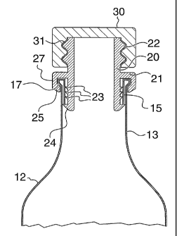
An alternative embodiment is shown in Fig. 3. In
this arrangement, a skirt portion 27 extends downwardly
from the annular ledge 21 outside the can neck 13, such
that the top end of the neck is held in an annular
groove. The folding of the neck 13 to form flange 15
includes an outwardly rounded rim portion 17. This
rounded rim portion provides stiffening for the neck as
well as an abutment to engage the inviardly directed lip
25 at the bottom edge of skirt portion 27. This helps to
prevent elongation growth of neck 13 caused by the flange
unfurling as the internal pressure pushes against the
closure cap 30.
In the same manner as Fig. 2, the ribs 23 bite into
the adjacent can metal to provide a gas-tight seal, and
15 the catches 24 engage the abutments 26 to prevent the
plastic sleeve from being ejected under gas pressure.
The combination of the gripping ribs 23, the catches 24
and the skirt portion 27 engaging the rounded rim 17 of
the can neck provide an overall secure attachment of the
threaded plastic sleeve 14 to the can neck 13.
Fig. 4 is a modifi.cation of the design of Fig. 3
with a different gripping arrangement between the annular
ledge skirt 27 and the neck portion 13. In this
embodiment, the neck portion has an annular indentation
16 which engages a mating annular projection 28 on the
inner face of the skirt portion 27.
It is desirable for customer appeal to have a bottle
shape with clean lines where the outer surface of the cap
and sleeve are flush with the outer surface of the neck
portion. An example of this can be seen in Fig. 5, where
the bottle neck has an indented upper portion 35, such
CA 02498114 2005-03-08
WO 2004/024574 PCT/CA2003/001187
8
that skirt portion 36 mates with the indented portion 35
with the outer face 37 of skirt portion 36 flush with the
outer face of neck portion 13. The remainder of this
design is similar to Figs. 3 and 4.
Fig. 6 shows a design in which the threaded plastic
sleeve is mounted over the projecting neck. In this
design, a portion 40 of the can neck i.s turned outwardly
and downwardly providing an abutment 41. The threaded
sleeve has a lower tubular portion 42, with a plurality
of axially spaced annular gripping ribs 43 extending
inwardly from the inner face of tubular portion 42.
These grip the face of the neck in the same manner as
described hereinbefore. At the top of the lower tubular
portion is a ledge 44 which projects both inwardly and
outwardly. Extending up from ledge 44 is an upper
tubular portion 45 with external threads 46, adapted to
receive the internal threading 31 of closure cap 30.