Note : Les descriptions sont présentées dans la langue officielle dans laquelle elles ont été soumises.
CA 02503459 2005-O1-21
WO 2004/009294 PCT/IL2003/000601
BAR CLAMP
FIELD OF THE INVENTION
The present invention relates generally to bar clamps.
BACKGROUND OF THE INVENTION
Bar clamps are well known tools used in many carpentry and handicraft
applications. Bar clamps generally comprise a pair of clamping jaws that slide
along a
bar. A workpiece may be clamped between the jaws by abutting the jaws against
opposite
sides of the workpiece, and then tightening the jaws against the worlcpiece,
such as by
repetitive squeezing of a ha~id-held trigger mechanism.
The bar clamp may also be used to spread objects apart. This may be
accomplished by turning around the clamping jaws 180°, which reverses
the advancing
movement of the j aws along the bar towards each other into a retreating
movement away
from each other. The objects may be spread apart by abutting the jaws against
the
appropriate surfaces of the obj ects, and then moving the j aws in the
spreading direction,
such as by repetitive squeezing of the hand-held trigger mechanism.
US Patent 6,382,608 to Michell describes a bar clamp having a fixed jaw and a
movable jaw opposing the fixed jaw, where the fixed jaw and the movable jaw
each
include two jaw pads facing in opposite directions. The fixed jaw and the
movable jaw
are not at the same height relative to the bar. Two ratchet means are provided
for
advancing the movable jaw in mutually opposite directions along the bar.
SUMMARY OF THE INVENTION
The present invention seeks to provide a novel bar clamp, which may be used
for
clamping or spreading without having to turn the clamping jaws around
180°. The present
invention preferably includes double-faced clamping jaws, wherein one face
(e.g., the left
face) may be used for clamping, while the other face (e.g., the right face)
may be used for
spreading. A novel jaw-advancing mechanism is described for moving the jaws
towards
or away from one another. The bar of the bar clamp may be provided with a
protective
cap at an end thereof, so as to prevent marring of objects and to protect the
bar from
damage.
BRIEF DESCRIPTION OF THE DRAWINGS
The present invention will be understood and appreciated more fully from the
following detailed description taken in conjunction with the drawings in
which:
Fig. 1 is a simplified pictorial, front-view illustration of a bar clamp,
constructed
and operative in accordance with an embodiment of the present invention;
CA 02503459 2005-O1-21
WO 2004/009294_ PCT/IL2003/000601
2
Fig. 2 is a simplified pictorial, partially exploded illustration of the bar
clamp of
Fig. 1;
Fig. 3 is a more detailed illustration of a jaw-advancing mechanism of the bar
clamp of Fig. 1, constructed and operative in accordance with an embodiment of
the
present invention;
Fig. 4 is a simplified sectional illustration of the jaw-advancing mechanism
of the
bar clamp of Fig. l, in a first position for advancing one of the jaws in a
first direction;
and
Fig. 5 is a simplified sectional illustration of the jaw-advancing mechanism
of the
bar clamp of Fig. 1, in a second position for advancing one of the jaws in a
second
direction opposite to the first direction.
DETAILED DESCRIPTION OF THE PREFERRED EMBODIMENT
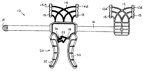
Reference is now made to Fig. 1, which illustrates a bar clamp 10, constructed
and
operative in accordance with a preferred embodiment of the present invention.
Bar clamp 10 may include first and second clamping jaws 12 and 14 mounted on a
bar 16. First clamping jaw 12 may be fixedly attached to bar 16, whereas
second
clamping jaw 14 may be slidingly mounted on bar 16. At least one of, and
preferably
both, clamping jaws 12 and 14 may comprise a double-faced clamping jaw
comprising
one face (12A and 14A, respectively) facing one end of bar 16 and another face
(12B and
14B, respectively) facing an opposite end of bar 16. The double-faced clamping
jaws may
be molded as one integral piece and may have non-marring pads 18 mounted on
both
faces thereof. A protective cap 19 may be mounted at an end of bar 16 so as to
prevent
rriairing of objects and to protect bar 16 from damage. Cap 19 may be made of
any
suitable material, such as but not limited to, polyurethane or rubber. Cap 19
may be
slidable along bar 16 and used for marking the position of the clamping jaws
12 and 14
relative to one another. This feature may be useful when it is desired to have
a similar
spacing between the jaws for other workpieces.
A jaw-advancing mechanism 20 may be coupled to second clamping jaw 14 for
selectively moving second clamping jaw 14 towards or away from first clamping
jaw 12,
as is now described in detail.
The jaw-advancing mechanism 20 may comprise a selector knob 22 with two
positions 24 and 26, as indicated in Fig. 1. In position 24, jaw-advancing
mechanism 20
brings first and second clamping jaws 12 and 14 towards each other, such that
a
workpiece (not shown) may be clamped between face 14B of second clamping jaw
14
CA 02503459 2005-O1-21
WO 2004/009294- PCT/IL2003/000601
3
and face 12A of first clamping jaw 12. This direction may be indicated by an
arrow-shape
of selector knob 22 pointing towards first clamping jaw 12. In position 26,
jaw-advancing
mechanism 20 moves first and second clamping jaws 12 and 14 away from each
other,
such that face 14A of second clamping jaw 14 and face 12B of first clamping
jaw 12 may
be used to spread apart workpieces. This direction may be indicated by the
arrow-shape of
selector knob 22 pointing away from first clamping j aw 12.
Reference is now made to Figs. 3 and 4, which illustrate jaw-advancing
mechanism 20 in more detail. Jaw-advancing mechanism 20 may comprise a pair of
trigger handles 30 and 32, which are pivotally mounted to a case 34. Gripping
elements
36 and 38 may be biased by biasing devices 40 and 42, respectively, such as
but not
limited to, coil springs, which abut against a portion of case 34. Biasing
device 40 urges
gripping element 36 in the direction of an arrow 43. Gripping element 36 is
free to slide
over bar 16 in the direction of arrow 43, but in the opposite direction,
indicated by an
arrow 44, gripping element 36 binds against bar 16 and prevents bar 16 from
moving with
respect to gripping element 36 in the direction of arrow 44. Similarly,
biasing device 42
urges gripping element 38 in the direction of arrow 44. Gripping element 38 is
free to
slide over bar 16 in the direction of arrow 44. However, gripping element 38
binds against
bar 16 and prevents bar 16 from moving with respect to gripping element 38 in
the
direction of arrow 43.
Jaw-advancing mechanism 20 may also include a selector gripping element 50,
which may straddle bar 16. One end of selector gripping element 50 may be
pivotally
received in a pivot recess 52. An opposite end of selector gripping element 50
may be
coupled by a flexible coupling 54 (e.g., a coil spring) to-a stub 56, which is
connected to
selector knob 22 (not shown for clarity in Fig. 4). In the position shown in
Figs. 3 and 4,
selector gripping element 50 is angled relative to bar 16 in the same general
angle as
gripping element 38, and stub 56 abuts against handle 32. In this position,
handle 32 may
not be squeezed, but handle 30 may be squeezed towards handle 32. Since
gripping
element 36 binds against bar 16, squeezing handle 30 moves gripping element 36
together
with bar 16 and first clamping jaw 12 in the direction of arrow 44, thereby
compressing
biasing device 40. The angle of gripping element 38 and selector gripping
element 50
relative to bar 16 permits bar 16 to pass through gripping element 38 and
selector
gripping element 50. The squeezing action brings clamping jaws 12 and 14
together.
Trigger handle 30 may be repeatedly squeezed until clamping jaws 12 and 14
come
together, or a workpiece (not shown) is firmly gripped between them.
CA 02503459 2005-O1-21
WO 2004/009294- PCT/IL2003/000601
4
Reference is now made to Fig. 5. In the position shown in Fig. 5, selector
gripping
element 50 is angled relative to bar 16 in the same general angle as gripping
element 36,
and stub 56 abuts against handle 30. In this position, handle 30 may not be
squeezed, but
handle 32 may be squeezed towards handle 30. Since gripping element 38 binds
against
bar 16, squeezing handle 32 moves gripping element 38 together with bar 16 and
first
clamping j aw 12 in the direction of arrow 43, thereby compressing biasing
device 42. The
angle of gripping element 36 and selector gripping element 50 relative to bar
16 permits
bar 16 to pass through gripping element 36 and selector gripping element 50.
The
squeezing action moves clamping jaws 12 and 14 apart. Trigger handle 32 may be
repeatedly squeezed to spread clamping jaws 12 and 14 apart.
It will be appreciated by person skilled in the art that the present invention
is not
limited by what has been particularly shown and described herein above. Rather
the scope
of the present invention is defined only by the claims that follow: