Note : Les descriptions sont présentées dans la langue officielle dans laquelle elles ont été soumises.
CA 02507197 2005-05-13
Field of invention
This invention relates to an improved floor covering system to be used as
underpad
underneath for many types of surface coverings or as floor covering without
surface covering
and which consists of panels made of one or more layers of material, the edges
of the panels
further comprising a locking system allowing two contiguous panels to be
securely attached
together.
Background of the invention
The use of resilient floor covering as playing surface in numerous sport is
not new.
Throughout the years, different floor coverings have been proposed. Some
proposed different
type of material such as rubber granules, expended polypropylene, expended
polyethylene,
polyurethane, etc. Others proposed the use of multiple layers floor covering,
each layer
having different thickness and different density.
Independent from the type of material or the number of layers, the vast
majority of these floor
covering come in the form of rectangular panels or rolls. To cover a surface,
several panels
are placed side by side.
However, it is often necessary for the floor covering to be removable. An
example is when
the ice surface in an arena is melted and replaced by another playing surface
for sports like
lacrosse and interior soccer. In this case, each panel must be ultimately
removable but must
not move during the utilization.
One type of locking system is a puzzle piece shaped panel. In this type of
locking system,
each panel comprises a plurality of locking fingers and locking aperture, as
in a puzzle piece.
To lock two panels together, one must align the locking fingers and the
locking apertures of
two contiguous panels and press fit the locking fingers in the locking
apertures. US patent no.
5,052,158 is a good example of such a locking system. However, under intense
use, it is
possible that the locking fingers disengage from the locking apertures, thus
creating a gap
between two panels. Also, if the locking fingers are not properly pressed into
the locking
apertures, the surface will be uneven at the joint of these two panels, which
is an unwanted
characteristic.
2
CA 02507197 2005-05-13
There is thus a need for a floor covering with an improved locking system
circumventing the
above-mentioned drawbacks.
S Summary of invention
The object of this invention is to provide an innovative improved floor
covering system which
consists of floor covering panels comprising a locking system on each of their
edges, enabling
them to be securely attached together.
In this new floor covering system, each floor covering panel is securely
attached to all its
neighboring panels. Thus, even when subjected to traction, strain and
expansion due to heat,
no crack, space or general displacement will appear between contiguous panels.
This prevents
injuries caused by uneven floor.
There is thus provided a floor covering system which comprises one or more
panels made of
one or more layers of resilient materials. In generally the middle portion of
each side of each
panel is fixedly attached one element of a locking system.
The locking system comprises a male element and a female element. The male
element
generally consists of a strip perpendicularly protruding from the side of a
panel and extending
approximately the full width of the side of the panel. The protruding end of
the strip has a
generally round shape which is thicker than the rest of the strip.
The female element of the locking system comprises a groove in the side of the
panel,
extending approximately the full width of the panel. The shape of the groove
generally
matches the shape of the male element.
A first method to attach two panels together comprises the following steps:
placing a first panel on the floor with one element of the locking system
facing where
the second panel will be placed;
placing a second panel on floor with the other element of the locking system
generally
facing the first element of the first panel;
3
CA 02507197 2005-05-13
connecting the second panel to the first by snapping the male element inside
the
female element of the locking system;
wherein the previous steps are repeated for each subsequent panel.
A second method to attach two panels together comprises the following steps:
placing a first panel on the floor with one element of the locking system
facing where
the second panel will be placed;
placing a second panel on floor with the other element of the locking system
generally
facing the first element of the first panel;
connecting the second panel to the first by sliding the male element inside
the female
element of the locking system;
wherein the previous steps are repeated for each subsequent panel.
The present invention also allows two locked panels to be unlocked, either by
unsnapping the
two panels or by sliding out the locking elements of both panels.
Other aspects and many of the attendant advantages will be more readily
appreciated as the
same becomes better understood by reference to the following detailed
description and
considered in connection with the accompanying drawings in which like
reference symbols
designated like elements throughout the figures.
The features of the present invention which are believed to be novel are set
forth with
particularity in the appended claims.
Brief description of figures
Figure 1 is an fractional isometric section view of the male element and the
female element of
the locking system not engaged.
Figure 2A is a close-up isometric sectional view of the male element sliding
in the female
element of the locking system upon installation.
Figure 2B is a close-up sectional side view of the male locking element
snapping in the
female locking element of the locking system upon installation.
4
CA 02507197 2005-05-13
Figure 3 is a fractional isometric view of a panel of the present invention
showing the groove.
Figure 4 is a fractional isometric sectional view of a section of another
embodiment of the
locking system.
Figure 5 is a fractional isometric view of another embodiment of the male
locking element.
Detailed description of preferred embodiments
The new floor covering system can be made of a single layer of any type of
cushion and
absorbent material. It can also be made of a plurality of layers of different
densities and
thickness. Each layer being made of any type of cushion and absorbent
material. Such
material are, but not limited to: EPP products (expanded and/or extruded
polypropylene close
cell beads molded into an open cell structure), foam products, EPE product
(expanded and/or
extruded polyethylene), EPDM products, crumb rubber tire products, plastic
products, natural
and or synthetic rubber products (including granules) and polyurethane
products.
Combinations of material are also possible.
It is to be noted that even if single layer floor covering with locking system
is shown in the
accompanying figures, it is in no way limitative and multiple layers floor
covering with
locking system can also be envisaged.
We can see in figure 3 a floor covering panel before the installation of the
locking system.
This panel 10, made of one or more layers of resilient material, has a
generally rectangular or
square shape. In figure 3, only a fraction of the panel 10 is shown. The panel
comprises a
groove 100, extending the full width of each side of the panel 10. The groove
100 is
preferably located in the middle of the height of each panel 10. The exact
location of the
groove 100 is not critical but it must be the same for each side of the panel
10. Otherwise,
once locked together, two contiguous panels 10 will not create an even
surface. The depth of
the groove 100 must be large enough so the locking system can be securely
attached in the
groove 100 of the panel 10.
5
CA 02507197 2005-05-13
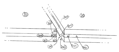
In figure 1, we can see two contiguous panels 20 and 30. Panel 20 comprises a
male locking
element fixed in the groove 100 of the panel 20. The male locking element 200
comprises a
base strip 201 extending almost the full width of the side of the panel 20.
The thickness of the
base strip 201 generally matches the thickness of the groove 100. The width of
the base strip
201 generally matches the depth of the groove 100. The base strip 201 is
preferably fixed to
the panel 20 with glue, adhesives or the like. Protruding from the base strip
201 is the male
locking strip 202. The male locking strip comprises a first flat portion 203
and an end portion
204. The end portion 204 is thicker than the flat portion 203. The shape of
the end portion
204 shown in figure I is illustrative in nature and by no means limitative.
Other shapes could
be used without departing from the scope of the invention. The male locking
strip also
extends almost the full width of the side of the panel 20. Space must be left
at both ends of
the male locking element 200 in order to allow the insertion of other locking
element (not
shown) in the grooves 100 of the other sides of the panel 20.
Still in figure 1, panel 30 comprises a female locking element 300. Female
locking element
300 comprises a base strip 301 which further comprises a female groove 302. As
for the
male base strip 201, female base strip 301 is preferably glued in groove 100.
The female
locking element extends almost the full width of the side of the panel 30.
Space, equivalent to
the depth of the groove 100 must be left at both end of the female locking
element 300. The
female groove 302 has a generally flat portion 303 and an end portion 304. The
shape of the
flat portion 303 and the end potion 304 of the female locking element must
generally match
the flat portion 203 and end portion 204 of the male locking element.
In figure 2A, we see a first way to lock the two panels 20 and 30 together.
The male locking
strip 202 of the element 200 of the panel 20 is first aligned with the female
groove 302 of the
female locking element 300. The panel 20 and thus the male locking strip 202
is then slid into
the female groove 302 of the female locking element 300 of the panel 30. Once
the panel 20
has been completely slid, both panels 20 and 30 are securely attached
together.
In figure 2B, we see another way to lock the two panels 20 and 30 together,
using the same
locking elements. In this case, the male locking strip 202 of element 200 is
placed face to
face with female groove 302 of element 300. Then, panel 20 is pushed so that
male locking
strip 202 is forced in female groove 302 until the end portion 204 of the male
locking strip
6
CA 02507197 2005-05-13
202 reaches the end portion 304 of the female groove 302. A distinctive
"snapping" sound
may be heard when the operation is completed.
The locking elements 200 and 300 prevent the panels 20 and 30 to be
unintentionally pulled
apart, thus creating a gap between the two panels that can be dangerous.
In figure 4, we can see another embodiment of the locking system. In this
case, two female
locking elements 300 are placed face to face. To lock the two female locking
elements 300
together and thus securing the two panels 30, an independent male locking
element 400 is slid
into both female grooves 302 of both locking elements 300.
Figure 5 shows the independent male locking element 400. This male locking
element 400 is
an elongated strip of rigid or semi-rigid material having three portions. The
first portion is the
central flat portion 401. The second and third portions are both ends 402 of
the locking
element 400. Both ends 402 must be thicker than the flat portion 401. The
shape of the ends
402 is not critical but must matches the shape of the female groove 302.
All the locking elements 200, 300 and 400 are made of rigid or semi-rigid
material such as
plastic. Also, the material must have a resiliency large enough to allow the
female groove to
be deformed temporarily during the "snapping" procedure. The resilience must
prevent
unintentional unsnapping of two panels during use but also allow intentional
unsnapping upon
dismantlement of floor panels.
The configurations of the locking elements (male and female) in each groove
100 of a panel
10 are numerous and panels with different configurations can be manufactured.
The choice of
configurations will depend upon the installation pattern of the floor covering
system. It is also
possible to combine both embodiments if the shape of all male and female
locking elements
are compatible.
While preferred embodiments of the invention have been described herein, it
should be
apparent to those skilled in the art that variations and modifications are
possible without
departing from the spirit of this invention. For example, the groove of each
side of the panel
may not extend for the full width of each side but only for a fraction of it.
Such an
7
CA 02507197 2005-05-13
arrangement would require that the locking elements are properly aligned. Such
an
arrangement would also only allow the snapping of contiguous panels.
8