Note : Les descriptions sont présentées dans la langue officielle dans laquelle elles ont été soumises.
CA 02513049 2005-07-22
GAS TURBINE FLOATING COLLAR
TECHNICAL FIELD
[0001] The invention relates generally to gas turbine
engine combustors and, more particularly, to a floating
collar therefor.
BACKGROUND OF THE ART
[0002] Gas turbine combustors are typically provided
with floating collars or seals to permit relative radial or
lateral motion between the combustor and the fuel nozzle
while minimizing leakage therebetween. The collar is
subject to wear and heat, and is therefore cast/machined
form a heat resistant material. As fuel nozzles,
combustors and related components must be periodically
removed for cleaning, inspection, repair and, occasionally
replacement, the floating collar arrangement is provided in
a manner which facilitates such removal, to thereby
facilitate maintenance. Floating collar arrangements have
become quite elaborate in the recent art, as designers
continuously improve gas turbine efficiency. Such
improvement, however, often comes at the expense of
economical operation for the operator, as elaborate parts
are typically more expensive to repair and replace.
Accordingly, there is a need to provide a solution which
addresses these and other limitations of the prior art, and
in particular, there is a need to provided economical
solutions to enable the emerging general aviation very
small turbofan gas turbine market.
CA 02513049 2012-02-14
SUMMARY OF THE INVENTION
[0003] In accordance with one aspect of the present
invention, there is provided a gas turbine combustor
floating collar assembly for receiving a fuel nozzle
swirler body, the combustor having a nozzle opening
defined in a dome thereof, the swirler body having an
abutment shoulder extending therearound, the assembly
comprising: a mounting arrangement including a mounting
flange spaced apart from the dome and circumscribing the
opening, the flange fixed to the exterior of the dome
immediately adjacent the opening, and a cap spaced apart
in an axial direction relative to the combustor from the
mounting flange, the cap fixed to the mounting flange;
and a sheet metal floating collar comprising an axial
extending annular collar portion, an annular flange
portion extending radially from the collar portion and a
smooth transition portion between the collar and flange
portions, the flange portion slidably trapped between the
mounting flange and the cap to thereby substantially
restrain relative axial movement of the collar relative
to the mounting arrangement but permit relative radial
movement, the collar portion of the collar having a
central aperture adapted for axial sliding engagement
with the nozzle body, the aperture being substantially
aligned with the dome opening when trapped between the
mounting flange and the cap.
[0004] In accordance with another aspect of the present
invention, there is also provided a method of
manufacturing a gas turbine engine combustor having a
liner and a dome with an opening therein adapted to
receive a fuel nozzle therethrough, the method comprising
2
CA 02513049 2012-02-14
the steps of: providing an annular sheet metal blank;
bending the blank towards a first direction extending
along a central axis of the annular metal blank to define
a floating collar having an axial extending annular
collar portion, an annular flange portion extending
radially from the collar portion and a continuously
smooth rounded transition portion between the collar and
flange portions, the continuously smooth rounded
transition portion defining a radius of curvature, the
annular collar portion extending axially from the flange
portion towards the first direction; providing a mounting
arrangement of the dome having a mounting flange and a
cap axially spaced apart, the mounting flange being fixed
to an exterior of the dome adjacent the opening; and
engaging the floating collar to the mounting arrangement
such that the annular flange portion is trapped between
opposed surfaces of the mounting flange and the cap, the
mounting flange and the cap being sufficiently spaced
apart to permit radial sliding motion of the floating
collar therebetween, the floating collar being engaged
such the collar portion extends within or is in alignment
with the opening and the first direction extends through
the opening toward an interior of the liner.
[0005] Further details of these and other aspects of the
present invention will be apparent from the detailed
description and Figures included below.
DESCRIPTION OF THE DRAWINGS
[0006] Reference is now made to the accompanying Figures
depicting aspects of the present invention, in which:
3
CA 02513049 2012-02-14
[0007] Figure 1 is a schematic longitudinal sectional
view of a turbofan gas turbine engine;
[0008] Figure 2 is a partial sectional view of a
combustor in accordance with an embodiment of the present
invention;
[0009] Figure 3 is an isometric view of a portion of
Figure 2; and
[0010] Figure 4 is an exploded isometric view of Figure
3.
DETAILED DESCRIPTION OF PREFERRED EMBODIMENTS
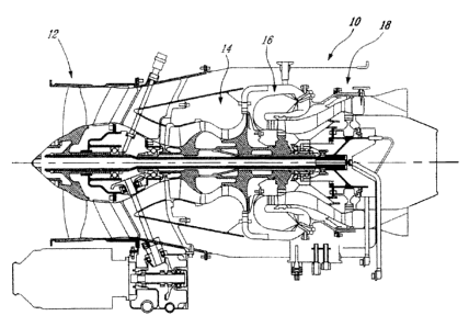
[0011] Figure 1 illustrates a gas turbine engine 10 of a
type preferably provided for use in subsonic flight,
generally comprising in serial flow communication a fan
12 through which ambient air is propelled, a multistage
compressor 14 for pressurizing the air, a combustor 16 in
which the compressed air is mixed with fuel and ignited
for generating an annular stream of hot combustion gases,
and a turbine section 18 for extracting energy from the
combustion gases.
[0012] Figure 2 shows an enlarged axial sectional view of
a combustor 16 having a liner 20 and a dome 22 having an
exterior side 24 and a central opening 26 for receiving
an air swirler fuel nozzle (depicted in stippled lines in
Figure 2) of the type generally described in U.S. Patent
Nos. 6,289,676 or 6,082,113, for example. A mounting
arrangement 28 is provided as will now be described.
[0013] An annular mounting flange 30 is fixedly bonded,
preferably by a weld 32, to the exterior side 24 of dome
4
CA 02513049 2012-02-14
22, and includes an axially-disposed annular portion 30a,
a radially disposed annular flange portion 30b, both
defining a central aperture 34 therein. Central aperture
34 can be aligned with dome opening 26 when mounting
flange 30 is mounted on the combustor. Mounting flange 30
may also include a plurality of legs 36 as will be
described further below.
[0014] An annular cap 40 is provided and fixedly bonded,
preferably by a weld 42, to mounting flange 30,
preferably at legs 36. Cap is provided in a spaced-apart
manner relative to mounting flange 30, as will be
described further below. Cap 40 has a central aperture 44
which is aligned with dome opening 26 when mounted on
combustor 16 and adapted to receive the fuel nozzle
therein.
[0015] A floating collar 50 is provided having an
axially-disposed nozzle collar portion 50a, and a
radially disposed annular flange portion 50b, both
surrounding a
4a
CA 02513049 2005-07-22
central aperture 54, and a smooth transition 50c joins
portions 50a and 50b. Central aperture 54 and collar
portion 50a are provided for axially slidingly engaging a
circumferential shoulder of the fuel nozzle swirler body
(stippled lines in Figure 2). Collar portion 50a
preferably extends to, or inside, dome 22 though opening
26. Flange portion 50b is trapped between opposed surfaces
of mounting flange 30 and cap 40, with mounting flange 30
and cap 40 being sufficiently spaced apart to permit radial
(relative to the engine axis of Figure 1) sliding motion to
occur between floating collar 50 and mounting flange 30/cap
40. An anti-rotation tang 56 depends from flange portion
50b and is likewise trapped between adjacent mounting
flange legs 36, to thereby limit the amount by which
floating collar 50 may rotate relative to mounting flange
30/cap 40.
[0016] In use, the fuel nozzle air swirler (not shown)
is positioned within central aperture 54 and delivers a
fuel air mixture to combustor 16. As forces acting upon
the fuel nozzle and the combustor tend to cause relative
movement therebetween, floating collar 50 is able to
displace radially with the nozzle while maintaining sealing
with respect to combustor through maintaining sliding
engagement with mounting flange 30 and cap 40. Welds 32
and 42 ensure that mounting flange 30 and cap 40 maintain
their spaced-apart relation and thereby keep floating
collar 50 trapped therebetween.
[0017] Referring to Figure 4, mounting arrangement 28 is
assembled through a process involving at least the
following steps: welding mounting flange 30 to combustor
CA 02513049 2005-07-22
dome 22 so that the flange central opening 36 is generally
aligned with dome opening 26; inserting floating collar 50
into the mounting flange 30, so that the collar portion 50a
extends through central opening 36 and is generally aligned
with dome opening 26, and preferably also so that anti-
rotation tang 56 is trapped between two closely adjacent
legs 36; and welding cap 40 to mounting flange 30,
preferably at legs 36, to slidingly trap the floating
collar between cap and the mounting flange. The order of
operations may be any suitable, and need not be
chronologically as described.
[0018] Mounting arrangement 28 and floating collar 50
are preferably provided from sheet metal using a suitable
fabrication process. An simplified example process is to
provide a sheet of metal, cut a blank, and perform at least
one bending operation to provide the floating collar.
Referring again to Figure 2, it is evident that a sheet
metal collar 50 has a continuous transition 50c is provided
as a result of a sheet metal forming operation, such a
bending, and helps strengthen the collar 50. Unlike prior
art collars made by investment casting and/or machining
processes (see US Patent Nos. 4,454,711, 4,322,945 and
6,497,105, for example), the present invention's use of
sheet metal advantageously permits a very light weight and
inexpensively-provided part, due to its simple geometry,
and yet provides good performance and reliability.
[0019] Unlike the prior art, the mounting assembly of
the present invention is geometrically simple, lightweight,
easy to manufacture and east to assemble. Contrary to the
prior art which teaches providing a high-cost device which
CA 02513049 2005-07-22
central aperture 54, and a smooth transition 50c joins
portions 50a and 50b. Central aperture 54 and collar
portion 50a are provided for axially slidingly engaging a
circumferential shoulder of the fuel nozzle swirler body
(stippled lines in Figure 2). Collar portion 50a
preferably extends to, or inside, dome 22 though opening
26. Flange portion 50b is trapped between opposed surfaces
of mounting flange 30 and cap 40, with mounting flange 30
and cap 40 being sufficiently spaced apart to permit radial
(relative to the engine axis of Figure 1) sliding motion to
occur between floating collar 50 and mounting flange 30/cap
40. An anti-rotation tang 56 depends from flange portion
50b and is likewise trapped between adjacent mounting
flange legs 36, to thereby limit the amount by which
floating collar 50 may rotate relative to mounting flange
30/cap 40.
[0016] In use, the fuel nozzle air swirler (not shown)
is positioned within central aperture 54 and delivers a
fuel air mixture to combustor 16. As forces acting upon
the fuel nozzle and the combustor tend to cause relative
movement therebetween, floating collar 50 is able to
displace radially with the nozzle while maintaining sealing
with respect to combustor through maintaining sliding
engagement with mounting flange 30 and cap 40. Welds 32
and 42 ensure that mounting flange 30 and cap 40 maintain
their spaced-apart relation and thereby keep floating
collar 50 trapped therebetween.
[0017] Referring to Figure 4, mounting arrangement 28 is
assembled through a process involving at least the
following steps: welding mounting flange 30 to combustor
CA 02513049 2005-07-22
facilitates replacement, the design and method of the
present invention instead has relatively low initial cost,
which assists in providing a lower-overall cost to the gas
turbine engine, thereby facilitating the provision of an
affordable general aviation turbofan engine, for example.
As well, because the initial cost is lower, the cost of
replacement may also be lowered.
[0020] The above description is meant to be exemplary
only, and one skilled in the art will recognize that
changes may be made to the embodiments described without
departing from the scope of the invention disclosed. For
example, the present invention may be applied to any gas
turbine engine, and is particularly suitable for airborne
gas turbine applications. The means by which flange 30 is
mounted to cap 40 may be different than that described.
For example legs 36 may be replaced or supplemented with a
continuous or discontinuous flange or lip, and/or may
extend from flange 30, cap 40 or both. The mode of anti-
rotation may be any desirable. Though welding is
preferred, brazing or other bonding methods may be used.
Other modifications which fall within the scope of the
present invention will be apparent to those skilled in the
art, in light of a review of this disclosure, and such
modifications are intended to fall within the equivalents
accorded to the appended claims.