Note : Les descriptions sont présentées dans la langue officielle dans laquelle elles ont été soumises.
CA 02515701 2007-09-28
1
POUND-IN GLIDE FOR AN ARTICLE OF FURNITURE
flACKGROtTND OF THE INVENTION
The present invention relates generally to furniture, and more particularly to
a
glide arrangement for an article of fumiture such as a chair, in which the
glide arrangement
is configured for connection to a tubular support associated with the article
of furniture.
There is a sizable and constant demand for rugged, comfortable and attractive
utility chairs of the type used in schools, auditoriums, convention centers,
hotels and the like.
In an educational setting, it is common for such a chair to have a frame that
supports a
desktop or worksurface, to form a desk that may be used in a classroom or the
like. These
types of chairs are subjected to continuous and rigorous use. Typically, the
frame for a chair
of this type includes a tubular metal member that is bent into a desired
configuration, which
often includes a section that is adapted to rest on a support surface such as
a floor. Typically,
casters or glides are employed to permit the arhicle of furniture to be slid
and thus shifted
from place to place without marring or excessively wearing the finish or
surface of the floor.
Certain known types of glide arrangements are attached to the tubular frame of
a chair or the like using rivets, screws or the like. For example, U.S. Patent
3,724,897
discloses a certain lcnown chair construction employing a glide arrangement
that includes
fastener glides fastened to runners of the chair by means of screws. While
this type of glide
arrangement functions satisfactorily to support the chair frame above a
support surface such
as a floor, it entails certain drawbacks in assembly and operation. For
example, a glide of
this type utilizes several components, which must be stocked separately and
which require
several steps in order to assemble the glide to the frame. In addition, the
use of a screw or
other fastener results in the head of the screw or other fastener becoming
exposed as the
surrounding areas of the glide wear away after extended periods of use. This
causes the
screw or fastener head to scratch or mar the floor or other surface during
movement of the
chair.
CA 02515701 2005-08-09
WO 2004/090350 PCT/US2004/010318
2
There thus exists a need for a glide arrangement that simplifies the
construction
and assembly of the glide to the article of fiarniture without sacrificing
protection of the floor
surface, and which prevents exposure of a fastener head in order to eliminate
the potential for
the glide to scratch the floor surface, even after extended usage.
SUMMARY OF THE INVENTION
The present invention contemplates a glide arrangement that is operable to
overcome the drawbacks of the prior art as discussed in the preceding
paragraphs by
providing a uniquely constructed, easily installed and durable glide
arrangement which
serves as a satisfactory glide and floor surface protector. The glide
arrangement of the
present invention is formed of a plastic or equivalent material which is of
requisite rigidity
and which is configured for quick and easy installation on a tubular support
for an article of
furniture, and which is capable of providing support for the article of
furniture while
protecting the floor or other support surface, even after extended periods of
use.
The glide arrangement of the present invention employs a floor engaging
member that includes a plug section configured to be slidably inserted through
an opening
fonned in a bottom support member of an article of furniture such as a chair.
The plug
section is capable of deflecting inwardly upon engagement with the opening in
the support
member. The plug section is then expandable into engagement with the edge area
of the
opening, to retain the plug section, and thereby the floor engaging member, in
engagement
with the support member of the article of furniture.
In one embodiment, the floor engaging member is in the form of a body having
an engagement surface configured to engage a downwardly facing surface of the
support
member. The plug section is in the form of a mounting boss having a plurality
of collapsible
mounting boss sections. The boss sections define an axial passage therebetween
and
extending through the body. When inserted into the opening in the support
member, the
edge of the opening engages the boss sections and moves the boss sections
radially inward
relative to the edge of the opening, toward a collapsed condition. The glide
arrangement
further includes a wedge configured to be driven by an applied force into the
passage defined
by the mounting boss sections. The driven wedge. is configured to move the
boss sections
CA 02515701 2005-08-09
WO 2004/090350 PCT/US2004/010318
3
apart and into engagement with the edge of the opening, to secure the body to
the support
member of the article of furniture.
In accordance with another aspect of the invention, the present invention
provides a glide arrangement for use in supporting an article of furniture.
The aa-ticle of
furniture includes one or more tubular members that support the article of
furniture on a floor
surface. The tubular member includes an opening configured to receive the
glide
arrangement. The glide arrangement includes a body having an upper surface and
a lower
surface. The upper surface has a series of boss sections having a space
therebetween. The
boss sections are configured to collapse radially inwardly, to allow the boss
sections to be
inserted through the opening in the tubular member. The glide arrangement also
includes a
wedge coupled to the body and aligned along an axis parallel to the boss
sections. The
wedge includes a series of radially-outward extending guide members aligned
generally
perpendicular relative to one other. The wedge is operable to force the
collapsed boss
sections in a radially outward direction such that the boss sections engage
against the edge of
the tubular member that defines the opening. Thereby, the pressure of the
wedge against the
boss sections secures the glide arrangement to the article of furniture.
The present invention also provides a method of mounting a support to an
article of furniture that includes an opening defined by an edge of a
furniture support
member. The method of the invention compi7ses the steps of inserting a
mounting boss
20, associated with the support into the opening, wherein the mounting boss
includes a number
of mounting boss sections that define a passage therebetween; moving the boss
sections into
the opening, so that the boss sections move radially inward to a collapsed
condition; driving
a wedge into the passage defined by the boss sections; and moving the
plurality of boss
sections radially outward via inward movement of the wedge, so that the boss
sections
engage against the edge of the opening to secure the support to the article of
furniture.
Various other features, objects and advantages of the invention will be made
apparent from the following description taken together with the drawings.
CA 02515701 2005-08-09
WO 2004/090350 PCT/US2004/010318
4
BRIEF DESCRIPTION OF THE DRAWINGS
The drawings illustrate the best mode presently contemplated of carrying out
the invention.
In the drawings:
FIG. 1 is an isometric view of an article of furniture employing the glide
arrangement of the present invention;
FIG. 2 is a detailed, partially exploded view of the glide arrangement of the
present invention for mounting to the article of fuiTiiture shown in FIG. 1;
FIG. 3 is a partial, enlarged isometric view of a glide arrangement assembled
on the article of furniture shown in FIG. 1;
FIG. 4 is an isometric view of the glide arrangement of the present invention;
FIG. 5 is a top view of the glide arrangement shown in FIG. 4;
FIG. 6 is a bottom view of the glide arrangement shown in FIG. 4;
FIG. 7 is a side elevation view of the glide arrangement or Fig. 4 coupled to
a
support member of an article of furniture, showing the glide arrangement in an
unfastened
position;
FIG. 8 is a side elevation view similar to Fig. 7, showing the glide
arrangement
in a fastened position;
FIG. 9 is a top view of the glide arrangement shown in the unfastened position
of Fig. 7;
FIG. 10 is a top view of the glide arrangement shown in the fastened position
of Fig. 8;
FIG. 11 is a partial cross section view along line 11-11 of FIG. 9;
FIG. 12 is a partial cross section view along line 12-12 of FIG. 10;
FIG. 13 is a partial cross section view along line 13-13 of FIG. 7;
FIG. 14 is a partial cross section view along line 14-14 of FIG. S; and
FIG. 15 is a partial cross section view along line 15-15 of FIG. 10.
CA 02515701 2005-08-09
WO 2004/090350 PCT/US2004/010318
DETAILED DESCRIPTION OF THE INVENTION
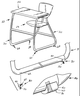
Referring to FIG. 1, a suppoi-t in the form of a glide arrangement 20 is
adapted
for connection to a surface of an article of fi.i.initure. In the illustrated
embodiment, the
article of fuxnita.re is in the form of a desk assembly 22 that includes a
frame structure having
5 a seat section 24 and a desk section 26, which are interconnected by a pair
of runners 30. In
this embodiment, the desk assembly 22includes a frame that is constructed of
metal tubing,
which is bent to the illustrated configuration and assembled together with the
seating and
desk components to form the desk assembly 22. The glide arrangements 20 are
mounted to
each runner 30 adjacent opposite ends defined by the runner 30. In this
manner, each glide
arrangement 20 functions to elevate each runner 30 relative to the floor or
other support
surface on which the desk assembly 22 is adapted to be placed. It should be
understood that
the illustrated construction is representative, and that the glide arrangement
20 may be used
in combination with any article of furniture, wall panel, or the like in which
it is desirable to
space a lower component of the fiirniture or wall panel above a floor surface,
or relative to
another component or any other surface.
Referring to FIGS. 2 and 4-6, the glide arrangement 20 generally includes a
body 40 in combination with a plug section or boss 45 and a wedge 50. The body
40 defines
an upper surface 55 configured to match the downwardly facing surface of the
runner 30. In
the illustrated enzbodiment, the upper surface 55 of the body 40 includes an
arcuate-shaped
channel configured to receive the arcuate-shaped outer surface of the runner
30. Again, it is
understood that the upper surface 55 of the body 40 can have any satisfactory
configuration,
and may not necessarily have a configuration that matches or corresponds to
the furniture
component to which the glide arrangement 20 is adapted to be mounted.
As illustrated in FIGS. 3, 4 and 7, the body 40 further includes an outer
surface
60 having a lower area adapted to rest on the floor or other supporting
surface for the article
of furniture. In the illustrated enibodiment, the lower area is arcuate-shaped
similar to the
arcuate-shape of the runner 30. Yet, it is understood that the configuration
of the lower area
of the outer surface 60 can vary.
CA 02515701 2005-08-09
WO 2004/090350 PCT/US2004/010318
6
Referring to FIGS. 2, 4, 5 and 7, the boss 45 is adapted to be inserted into
an
openiilg 62 formed in the runner 30. The boss 45 is divided into a number of
sections, which
may be in the form of four identically-shaped boss sections 65, each of which
is separated
from the adjacent boss section 65 by a gap or space 70. The boss sections 65
surround a
central passage 80, and the spaces 70 are in communication with the passage
80.
Each boss section 65 further includes a beveled or tapered inner edge 82. The
tapered edges 82 of the boss sections 65 are configured to enhance insertion
of the boss 45
into the hole 62 in the tubular frame structure of the runner 30, which has a
diameter smaller
than the diameter defined by boss 45. Yet, the shape (e.g., curvilinear,
stepped, square, etc.)
of the free ends of the boss sections 65 can vary.
Referring to FIGS. 4, 7 and 13, boss sections 65 extend upwardly from a base
section 88, which is defined by the central area of body 40. In the
illustrated embodiment,
boss sections 65 and base section 88 are formed integrally with each other.
A passage or opeiiing 90 is formed in base section 88, and extends along an
axial direction between the outer surface 60 of the body 40 and an upper edge,
shown at 91.
Passage 90 is configured to have a cross section that matches that of spaces
70 and passage
80 of boss 45. That is, passage 90 includes four generally perpendicular
passage sections
that radiate outwardly from a central axial section. As illustrated in FIGS. 4
and 7, each
space 70 between an adjacent pair of boss sections 65 is in communication and
alignnient
with one of the outwardly radiating sections of the passage 90, and passage 80
of boss
section 45 is in communication and alignment with the central axial section of
passage 90.
An annular recess 92 is formed in body 60 around boss 45. Recess 92
separates boss sections 65 from body 60 above the upper edge 91 of base
section 88. Recess
92 extends inwardly from an upper edge 93 that intersects with the upper
surface 55 of body
40, and the lower extent of recess 92 is defined by the upper edge 91 of base
section 88.
This construction enables the boss sections 65 to flex toward and away from
one other, for
reasons to be explained.
Referring to FIGS. 7, 9 and 11-13, the wedge 50 and the body 40 are
preferably formed of a thermoplastic material in the same molding operation,
such that the
CA 02515701 2008-07-25
7
wedge 50 and the body 40 are integrally coupled to one other. Wedge 50 is
molded in an
extended position in which wedge 50 extends outwardly from the outer surface
60 of the
body 40. FIG. 11 illustrates the manner in which wedge 50 is molded or formed
so as to be
interconnected with body 60. The wedge 50 includes an inner end 95 that is
interconnected
with the material of the body 40 via frangible tabs or connectors 100. As
shown in FIG. 7,
the inner end 95 of the wedge 50 :has a shape that corresponds to the outer
surface 60 of the
body 40, which in the illustrated embodiment is generally arcuate-shaped. As
it is molded or
formed as shown in FIG. 11, the inner end 95 of the wedge 50 is located
slightly inwardly
from the outer surface 60 of the body 40, and the frangible connectors 100
comprise portions
of material that extend between the inner end 95 of the wedge 50 and the
adjacent edges the
central axial section of passage 90, at a location at which passage 90 opens
onto the outer
surface 60 of the body 40. Each connector 100 is located between the inner
ends of an
adjacent pair of outwardly radiating sections of passage 90.
As illustrated in FIGS. 7, 8, 14, and 15, an outer end 97 of the wedge 50 is
also
arcuate-shaped, and defines an outer surface that corresponds to the arcuate
outer surface 60
of the body 40. When the wedge 50 is driven into the opening 90 of the body
40, as will be
explained, the outer end 97 of the wedge is generally flush with the outer
surface 60 of the
body 40 and acts with the body 40 to provide a glide and surface protector for
the article of
furniture.
Referring to FIGS. 4, 6-8, and 10, the wedge 50 includes an axially-extending
central section 105 integrally coupled with a series of radially-outward
extending guide
members 110 aligned generally perpendicular relative to one other. The central
section 105
has a cross-section that generally conforms to and is in alignment with that
of the central
passage 80 defined by the boss 45 and the central axial section of passage 90
in base section
88. Central section 105 has a length slightly greater than the combined
thickness of base
section 88 and height of boss 45. As shown in FIGS. 8 and 10, each guide
member 110 has a
cross-section that conforms to and is in alignment with one of spaces 70
defined by boss 45
and an aligned outwardly radiating section of passage 90. Each guide member
110 has a
lengtli slightly greater than the combined thickness of base section 88 and an
aligned one of
CA 02515701 2008-07-25
8
the spaces 70 between the boss sections 65. In the illustrated embodiment of
the wedge 50,
two of the guide members 110 are located in alignment with the longitudinal
axis 116 of the
body 40, and the other two of the guide menibers 110 are oriented
traiisversely to the
longitudinal axis 116 of the body 40, and in alignment with each other. Each
longitudinally
extending guide member I 10 may include a radially outwardly extending tab 120
operable to
be driven into an outer area 117 of one of the outwardly radiating sections of
passage 90 defined
in the body 40.
In operation, the glide arrangement 20 is mounted to the runner 30 as follows.
Initially, the hole 62 is formed in the runner 30 in the location at which the
glide arrangement
20 is to be mounted. The diameter of the hole 62 is smaller than the diameter
defined by the
boss 45. As noted previously, the runner 30 is formed of a tubular material,
such that the
material of the runner 30 defines a circular or curvilinear edge bordering the
hole 62, which
is in conununication with the passage defined by the runner 30 due to its
tubular
construction. The boss 45 of the wedge 50 is inserted into the hole 62 formed
in the runner
30.
As shown in FIGS. 7 and 13, the tapered edge 82 of each boss section 65
facilitates engagement of the boss 45 with the edge of the hole 62. An axial
force applied to
the body 40 (e.g., application of a pushing force on the body 40 on either
side of the wedge
50) fully inserts the boss 45 into the hole 62. As the boss 45 enters through
the hole 62, the
upper surface 55 of the body 40 engages the surface of the runner 30 adjacent
to the hole 62.
The edge of the hole 62 rides along the outer surfaces of the boss sections 65
to cause the
boss sections 65 to collapse together. The collapse of the boss sections 65
closes the spaces
70 between the adjacent boss sections 65 and moves boss sections 65 inwardly
into the
central passage 80. The outer surfaces of boss sections 65 engage the edge of
hole 62, to
maintain the glide arrangement 20 in .frictional engagement with runner 30.
After the boss sections 65 collapse upon insertion of the boss 45 into the
hole
62, the user pounds or applies an axial insertion force to move the wedge 50
inward through
the ilole 62, typically by strilcing the outer end 97 of wedge 50. The inward
force applied to
wedge 50 breaks frangible tabs 100 between the body 40 and the wedge 50, as
illustrated in
CA 02515701 2005-08-09
WO 2004/090350 PCT/US2004/010318
9
FIG. 12, and causes wedge 50 to move into passage 90 in base section 88. As
shown in
FIGS. 8 and 10, continued inward movement of the wedge 50 forces each guide
member 110
into the aligned space 70 between boss sections 65, and also forces the
central section 105 of
the wedge 50 into the central passage 80. Such inward movement of the wedge 50
also
forces the collapsed together boss sections 65 to move radially outwardly
apart relative to
one another. Such outward movement of the boss sections 65 by inward movement
of
wedge 50 functions to drive the outer surfaces of the boss sections 65 into
engagement with
the edge of the opening 62. The outer surface of each boss section 65 engages
the edge of
the opening 62 in the vicinity of each boss section 65 adjacent the upper
surface 55 of the
body 40. In this manner, the edge of the opening 62 digs into each boss
section 65,
functioning to maintain the body 40 in engagement with the runner 30.
FIGS. 3, 8, 10, and 14-15 illustrate the glide arrangement in a fastened
positioned. The wedge 50 is driven into the body 40 such that the outer end 97
of the wedge
50 is flush with the outer surface 60 of the body 40 and the outwardly
extending tabs 120 are
received in one of the outwardly radiating sections of passage 90. The
configuration of the
outer end of the wedge 50 is of a shape that enables the wedge 50 to be
positioned in a flush
relationship with the outer surface 60 of the body 40.
It' can thus be appreciated that the glide arrangement 20 provides a one piece
construction that combines both the glide itself as well as the means by which
the glide is
coupled to the article of furniture. This arrangement replaces a three piece
assembly of the
prior art, which includes a glide, a washer and a screw that is threaded into
a tapped hole
formed in the runner or otller furniture components to which the glide is to
be assembled.
This construction further eliminates the need to tap the hole used to mount
the glide.
Accordingly the present invention provides a significant decrease in the
number of parts that
must be handled in order to mount the glide to the article of furniture, and
also provides a
mounting method which is quicker and simpler than in the prior art.
While the invention has been shown and described with respect to a specific
embodiment, it is contemplated that certain details may vary from the specific
construction
as disclosed, while sti11 falling within the scope of the present invention.
For example, and
CA 02515701 2005-08-09
WO 2004/090350 PCT/US2004/010318
without limitation, while boss 45 is illustrated as having a round cross
section, it is
contemplated that the cross section of the space 70 may also be noncircular.
In an
arrangexnent such as this the opening of the fui-iliture component has a
corresponding shape,
and in any event must have a configuration that functions to collapse the boss
sections when
5 the boss is inserted into the opening. Fui.-ther, while the boss 45 is shown
as being divided
into four sections, it is also contemplated that the boss 45 may be divided
into any number of
sections which can be collapsibly engaged within the opening and then forced
outwardly into
engagement with the edges of the opening. In addition, it is also contemplated
that the
wedge 50 may be formed separately from the body 40. While this does not
provide the one
10 piece construction as shown and described, and nonetheless reduces the
overall part count
and provides a significantly simpler and quicker installation method, relative
to the known
prior art, by providing a pound-in construction rather than a construction
that is secured in
place via a screw-type fastener. In addition, while the glide arrangement of
the present
invention lias been shown and described as being engaged with a tubular
support for the
article of furniture, it is understood that the glide arrangement of the
invention may be
mounted to any portion of an article of furniture that faces a support surface
such as a floor,
and which is capable of having an opening formed therein for receiving and
mounting the
glide arrangement. In addition, it is understood that the glide arrangement of
the present
invention maybe used in connection with any type of furniture, and is not
limited to use in
conibination with a desk as shown and described.
Various alternatives and embodiments are contemplated as being within the
scope of the following claims particularly pointing out and distinctly
claiming the subject
matter regarded as the invention.