Sélection de la langue

Search

Sommaire du brevet 2515799 

Énoncé de désistement de responsabilité concernant l'information provenant de tiers

Une partie des informations de ce site Web a été fournie par des sources externes. Le gouvernement du Canada n'assume aucune responsabilité concernant la précision, l'actualité ou la fiabilité des informations fournies par les sources externes. Les utilisateurs qui désirent employer cette information devraient consulter directement la source des informations. Le contenu fourni par les sources externes n'est pas assujetti aux exigences sur les langues officielles, la protection des renseignements personnels et l'accessibilité.

Disponibilité de l'Abrégé et des Revendications

L'apparition de différences dans le texte et l'image des Revendications et de l'Abrégé dépend du moment auquel le document est publié. Les textes des Revendications et de l'Abrégé sont affichés :

  • lorsque la demande peut être examinée par le public;
  • lorsque le brevet est émis (délivrance).
(12) Brevet: (11) CA 2515799
(54) Titre français: DISPOSITIF AMELIORE DE RETENUE DE CLOUS ET MACHINE A CLOUER EQUIPEE D'UN TEL DISPOSITIF
(54) Titre anglais: AN IMPROVED NAIL RESTRAINER AND A NAILING MACHINE EQUIPPED WITH SAID RESTRAINER
Statut: Réputé périmé
Données bibliographiques
(51) Classification internationale des brevets (CIB):
  • B25C 1/00 (2006.01)
  • B25C 5/16 (2006.01)
(72) Inventeurs :
  • LI, XIAORONG (Chine)
(73) Titulaires :
  • ZHE JIANG RONGPENG AIR TOOLS CO., LTD. (Chine)
  • LI, XIAORONG (Chine)
(71) Demandeurs :
  • ZHE JIANG RONGPENG AIR TOOLS CO., LTD. (Chine)
  • LI, XIAORONG (Chine)
(74) Agent: GOWLING WLG (CANADA) LLP
(74) Co-agent:
(45) Délivré: 2008-09-30
(86) Date de dépôt PCT: 2003-04-17
(87) Mise à la disponibilité du public: 2004-09-10
Requête d'examen: 2006-05-12
Licence disponible: S.O.
(25) Langue des documents déposés: Anglais

Traité de coopération en matière de brevets (PCT): Oui
(86) Numéro de la demande PCT: PCT/CN2003/000279
(87) Numéro de publication internationale PCT: WO2004/076128
(85) Entrée nationale: 2005-08-11

(30) Données de priorité de la demande:
Numéro de la demande Pays / territoire Date
03204610.3 Chine 2003-02-25

Abrégés

Abrégé français

La présente invention a trait à un dispositif amélioré de retenue de clous d'une machine à clouer comportant un nez situé à l'avant de la machine à clouer, une coiffe de nez relié au nez. Dans ledit nez, est formé un trou traversant qui permet le passage d'agrafes ou de clous droits et une rainure de guidage qui permet le coulissement desdites agrafes ou desdits clous. Une nervure élastique qui s'étend dans la rainure de guidage est située sur la coiffe de nez, et une extrémité de ladite nervure élastique est solidaire du corps de la coiffe de nez. Dans la présente invention, la structure intégrale entre l'élastique et la coiffe de nez permet non seulement une fabrication plus facile mais également un contrôle aisé de l'ampleur de la courbe de la nervure élastique, en vue de réduire le taux de rejet ; en outre, cela peut également réduire le nombre d'opérations pour la mise en place de la nervure élastique, réduisant ainsi de coût de production.


Abrégé anglais


An improved nail restrainer for a nailing machine comprises a nose located in
the front of
the nailing machine and a nose cover coupled with said nose, in said nose
there are formed
a through hole allowing staples or straight nails to pass therethrough and a
guiding groove
allowing said staples or straight nails to slide therealong, an elastic rib is
provided on the
nose cover and extends into said guiding groove, one end of the elastic rib is
integral with
the nose cover body. In the present invention, because of the integral
structure between the
elastic rib and nose cover, it is much easier to be manufactured, the bend
extent of the
elastic rib is easy to be controlled, and therefore the rejection rate is
lowered. Moreover, as
no assembling procedure for the elastic rib is needed, the cost is cut down.

Revendications

Note : Les revendications sont présentées dans la langue officielle dans laquelle elles ont été soumises.


CLAIMS

1. An improved nail restrainer for a nailing machine comprising:
a nose (3) located in the front of the nailing machine, in which there is
formed a
through hole (31) allowing staples or straight nails to pass therethrough and
a guiding
groove (32) allowing said staples or straight nails to slide therealong;
a nose cover (4) coupled with said nose;
an elastic rib (5) provided on said nose cover (4) and extending into said
guiding
groove (32), and wherein: one end of said elastic rib (5) is integral with
said nose cover
(4).
2. An improved nail restrainer for a nailing machine according to Claim 1,
wherein said
elastic rib (5) is a tongue-shaped element of a constant width.
3. An improved nail restrainer for a nailing machine according to Claim 1,
wherein said
elastic rib (5) inclines gradually towards said guiding groove (32) from its
connected
end to its free end, and said free end protrudes from said nose cover (4).
4. An improved nail restrainer for a nailing machine according to Claim 1,
wherein a head
of said free end of said elastic rib (5) is arc in shape.
5. An improved nail restrainer for a nailing machine according to Claim 1,
wherein there
are a plurality of through holes (43, 44 and 45) in said nose cover (4), and
there are a
plurality of through holes (33, 34 and 35) which correspond to said through
holes (43,
44 and 45) in said nose (3).
6. An improved nail restrainer for a nailing machine according to Claim 1,
wherein there
is a recessed portion (42) formed at one side of said nose cover (4).
7. A nailing machine having a nail restrainer, said nail restrainer
comprising:
a nose (3) located in the front of the nailing machine, in which there is
formed a
through hole (31) allowing staples or straight nails to pass therethrough and
a guiding
groove (32) allowing said staples or straight nails to slide therealong;
a nose cover (4) coupled with said nose;
an elastic rib (5) provided on said nose cover (4) and extending into said
guiding
groove (32), and wherein: one end of said elastic rib (5) is integral with
said nose cover
(4).
8. A nailing machine according to Claim 7, wherein said elastic rib (5) is a
tongue-shaped
element of a constant width.
9. A nailing machine according to Claim 7, wherein said elastic rib (5)
inclines gradually


towards said guiding groove (32) from its connected end to its free end, and
said free
end protrudes from said nose cover (4).
10. A nailing machine according to Claim 7, wherein a head of said free end of
said elastic
rib (5) is arc in shape.
11. A nailing machine according to Claim 7, wherein there are a plurality of
through holes
(43, 44 and 45) in said nose cover (4), and there are a plurality of through
holes (33, 34
and 35) which correspond to said through holes (43, 44 and 45) in said nose
(3).
12. A nailing machine according to Claim 7, wherein there is a recessed
portion (42)
formed at one side of said nose cover (4).

6

Description

Note : Les descriptions sont présentées dans la langue officielle dans laquelle elles ont été soumises.


CA 02515799 2005-08-11

AN IMPROVED NAIL RESTRAINER AND A NAILING MACHINE EQUIPPED
WITH SAID RESTRAINER

FIELD OF THE INVENTION:
The present invention relates to an improved nail restrainer and a nailing
machine
equipped with said restrainer.

BACKGROUND OF THE INVENTION:
In prior art, in order to get better performance to nail straight nails and
staples, most nailing
] 0 machines are equipped with a nail restrainer for restraining both straight
nails and staples,
so that tiie nailing machines can work for different kinds of nails. In
general, the nail
restrainer for the dual-purpose nailing machine comprises three separate
components,
namely: nose cover, elastic rib and nose. The elastic rib is connected to the
nose cover
through a connecting member. For instance, Chinese Utility Model patent No.
01270742.2
discloses a nail restrainer which comprises a nose and a separable nose cover
which is
locked onto the nose. On the nose cover, there is an elastic rib, one end of
which is
pivotally coupled to the nose cover. The elastic rib is placed in a nail slot
to restrain the
nails. As the elastic rib is separable from the nose cover, there exist some
shortcomings
during production, such as: it is difficult to control the bend extent of the
elastic rib and the
rejection rate is very high. Moreover, it adds an extra step of assembling the
elastic rib.
SUMMARY OF THE INVENTION:
The object of present invention is to overcome the disadvantages of the above-
mentioned
prior art, and to provide an improved nail restrainer and a nailing machine
equipped with
such restrainer. This nail restrainer is much easier to be manufactured and
has a lower
rejection rate.

The nail restrainer according to the present invention comprises a nose
located in the front
of the nailing machine and a nose cover coupled with the nose. In the nose,
there are a
through hole allowing staples or straight nails to pass therethrough and a
guiding groove
allowing the staples or straight nails to slide therealong. An elastic rib is
provided on the
nose cover and extends into the guiding groove, and one end of the elastic rib
is integral
with the nose cover body.

1


CA 02515799 2005-08-11

As the elastic rib is integral with the nose cover, the nail restrainer
according to the present
invention is easier to be manufactured, the bend extent of the rib is easier
to be controlled,
and therefore the rejection rate is lowered. Moreover, as no assembling
procedure for the
elastic rib is needed in the present invention, the cost is cut down.


DESCRIPTION OF THE DRAWINGS :

FIG. 1 is a schematic diagram of the nail restrainer for a nailing machine in
prior art.
FIG 2 is a front view of the nose cover and elastic rib of the improved nail
restrainer
according to the present invention.
FIG. 3 is a cross sectional view along the line A-A of FIG. 2 showing the nose
cover and
the rib.
FIG. 4 is a front view of the nose of the improved nail restrainer according
to the present
invention.
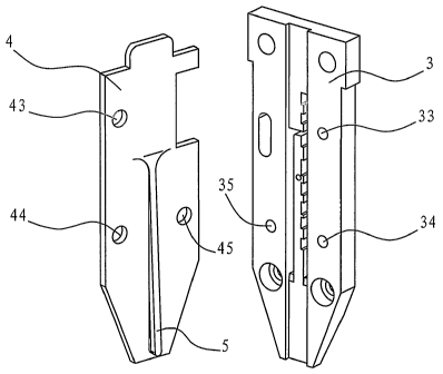
FIG 5 is an exploded view showing the improved nail restrainer according to
the present
invention.

EMBODIMENTS:
Referring to FIG. 1, a nail restrainer in prior art is illustrated, which
comprises three
separate components, namely: nose cover 1, elastic rib 2 and nose 3. There is
a pivot hole
21 in one end of the elastic rib 2 and this end of the elastic rib 2 is
connected with the nose
cover 1 by an elastic cylindrical straight pin 22. On the other end of the
elastic rib 2, there
is a protruding part which extends into the guiding groove of the nose 3.
During
manufacture, it is difficult to control the bend extent of the protruding part
of the elastic rib
2 and the rejection rate is very high.

Referring to FIGS. 2-5, an improved nail restrainer according to the present
invention
comprises a nose 3 located in the front of the nailing machine and a nose
cover 4 coupled
with the nose 3. Assembling of the nose 3 and a nailing machine is realized by
conventional techniques, and therefore is not described here. In the nose 3
there are formed
a through hole 31 allowing staples or straight nails to pass therethrough and
a guiding
groove 32 allowing the staples or straight nails to slide therealong. An
elastic rib 5 is
provided on the nose cover 4 and extends into the guiding groove 32. Different
from the
2


CA 02515799 2005-08-11

prior art, in present invention one end of the elastic rib 5 is integral with
the body of the
nose cover 4.

FIGS. 2 and 3 illustrate the structures of the nose cover 4 and the elastic
rib 5. The elastic
rib 5 is formed as a part of the nose cover 4. It is a tongue-shaped element
of a constant
width made through cutting and stamping processes. The elastic rib 5 inclines
gradually
towards the guiding groove 32 from its connected end to its free end. A head
of the free
end is arc in shape and protrudes from the nose cover 4.

As shown in FIG. 4, the structure of the nose 3 is illustrated, in the nose 3
there is formed a
guiding groove 32 allowing staples or straight nails to slide therealong. The
through hole
31 is a U-shaped hole formed inside the groove 32, so that the staples can
pass
therethrough. On one side of the U-shaped through hole there are a plurality
of T-shaped
through holes allowing straight nails of various models to pass therethrough.

As shown in FIG. 5, there are a plurality of through holes 43, 44 and 45 in
the nose cover 4
and there are a plurality of through holes 33, 34 and 35 in the nose 3. The
through holes 43,
44 and 45 correspond to the holes 33, 34 and 35 on a one-to-one basis. The
nose cover 4
and the nose 3 are fixed together by bolts which pass through the through
holes 43, 44 and
45 and the through holes 33, 34 and 35, such that the elastic rib 5 extends
into the guiding
groove 32 and divides the width of the groove into two portions, on each side,
the width
shall at least be large enough to allow straight nails or one side of staples
to pass
therethrough. On one side of the nose cover 4, there is formed a recessed
portion 42 for
facilitating installation of a safety stand. As the installation of the safety
stand is of
conventional technology, it is not described here.

As shown in FIGS. 2-5, the function of the elastic rib 5 in the nailing
machine is as
follows: When the nailing machine is not in operation, the elastic rib 5
always presses
against the middle part of the guiding groove 32 of the nose 3. While nailing
straight nails,
the nail feeder feeds straight nails into guiding groove 32 through one side
of the elastic rib
5. In this case, the elastic rib serves as a directional guide. While nailing
staples, the nail
feeder feeds staples into the guiding groove 32 through the staple slot.
During the nailing
operation, the striker pushes away the elastic rib 5 and drives out the staple
or straight nail.
3


CA 02515799 2005-08-11

During this period, the elastic rib 5 remains pressing against the striker.
Apparently, those skilled in the art can use the improved nail restrainer
according to
present invention to form various kinds of nailing machines.

The above embodiment is used to explain the present invention only, and not to
limit the
interpretation of this invention. It will be understood by those skilled in
the art that various
changes in form and details are possible without departing from the spirit and
scope of the
present invention as defined by claims.

4

Dessin représentatif
Une figure unique qui représente un dessin illustrant l'invention.
États administratifs

Pour une meilleure compréhension de l'état de la demande ou brevet qui figure sur cette page, la rubrique Mise en garde , et les descriptions de Brevet , États administratifs , Taxes périodiques et Historique des paiements devraient être consultées.

États administratifs

Titre Date
Date de délivrance prévu 2008-09-30
(86) Date de dépôt PCT 2003-04-17
(87) Date de publication PCT 2004-09-10
(85) Entrée nationale 2005-08-11
Requête d'examen 2006-05-12
(45) Délivré 2008-09-30
Réputé périmé 2011-04-18

Historique d'abandonnement

Il n'y a pas d'historique d'abandonnement

Historique des paiements

Type de taxes Anniversaire Échéance Montant payé Date payée
Enregistrement de documents 100,00 $ 2005-08-11
Le dépôt d'une demande de brevet 400,00 $ 2005-08-11
Taxe de maintien en état - Demande - nouvelle loi 2 2005-04-18 100,00 $ 2005-08-11
Taxe de maintien en état - Demande - nouvelle loi 3 2006-04-18 100,00 $ 2006-02-09
Requête d'examen 800,00 $ 2006-05-12
Taxe de maintien en état - Demande - nouvelle loi 4 2007-04-17 100,00 $ 2007-02-05
Taxe de maintien en état - Demande - nouvelle loi 5 2008-04-17 200,00 $ 2008-02-28
Taxe finale 300,00 $ 2008-06-25
Taxe de maintien en état - brevet - nouvelle loi 6 2009-04-17 200,00 $ 2009-03-26
Titulaires au dossier

Les titulaires actuels et antérieures au dossier sont affichés en ordre alphabétique.

Titulaires actuels au dossier
ZHE JIANG RONGPENG AIR TOOLS CO., LTD.
LI, XIAORONG
Titulaires antérieures au dossier
TAI ZHOU RONG PEN AIR TOOLS CO., LTD.
Les propriétaires antérieurs qui ne figurent pas dans la liste des « Propriétaires au dossier » apparaîtront dans d'autres documents au dossier.
Documents

Pour visionner les fichiers sélectionnés, entrer le code reCAPTCHA :


Pour visualiser une image, cliquer sur un lien dans la colonne description du document. Pour télécharger l'image (les images), cliquer l'une ou plusieurs cases à cocher dans la première colonne et ensuite cliquer sur le bouton "Télécharger sélection en format PDF (archive Zip)" ou le bouton "Télécharger sélection (en un fichier PDF fusionné)".

Liste des documents de brevet publiés et non publiés sur la BDBC .

Si vous avez des difficultés à accéder au contenu, veuillez communiquer avec le Centre de services à la clientèle au 1-866-997-1936, ou envoyer un courriel au Centre de service à la clientèle de l'OPIC.


Description du
Document 
Date
(yyyy-mm-dd) 
Nombre de pages   Taille de l'image (Ko) 
Page couverture 2005-10-17 1 42
Revendications 2008-01-10 2 69
Dessins 2008-01-10 3 40
Revendications 2005-08-11 1 39
Abrégé 2005-08-11 1 20
Description 2005-08-11 4 171
Dessins 2005-08-11 3 39
Dessins représentatifs 2005-08-11 1 10
Description 2005-08-12 4 173
Revendications 2005-08-12 2 70
Dessins représentatifs 2008-09-17 1 10
Abrégé 2008-09-17 1 20
Page couverture 2008-09-25 1 45
PCT 2005-08-11 1 67
Cession 2005-08-11 10 248
Cession 2005-10-25 3 81
PCT 2005-08-11 15 458
Poursuite-Amendment 2005-08-11 8 278
Taxes 2006-02-09 1 36
Poursuite-Amendment 2006-05-12 1 43
Taxes 2007-02-05 1 41
Poursuite-Amendment 2007-10-16 2 57
Poursuite-Amendment 2008-01-10 4 130
Taxes 2008-02-28 1 42
Correspondance 2008-06-25 2 52
Taxes 2009-03-26 1 33