Note : Les descriptions sont présentées dans la langue officielle dans laquelle elles ont été soumises.
CA 02516014 2005-08-16
1
Sunshade, umbrella or the like.
The present invention concerns a sunshade, umbrella or
the like of the type which consists of a support and a
screen, whereby the support is situated next to the
screen.
Sunshades and the like are known which mainly consist of
a vertical support onto which is fixed a screen by
means of an arm which is hinge-mounted to the support
l0 with one far end and which is hinge-mounted to the
screen with its other far end.
With such known sunshades, the above-mentioned arm may
hinge between a position whereby the arm is positioned
horizontally next to the support and a position in which
the arm extends crosswise in relation to the support.
The screen itself can hereby be put in an open or closed
position when the arm is situated in the transverse
position.
A disadvantage of such known sunshades and the like is
that they must always comprise means for hinging the arm
on the one hand and for opening the screen on the other
hand, as a result of which such sunshades or the like are
rather complex and fragile, and as a result of which
opening or closing such known sunshades or the like is
relatively time-consuming.
CA 02516014 2005-08-16
2
Another disadvantage of such known sunshades and the
like is that, for their automation, two different drives
must be provided, more particularly one for the hinging of
the arm and another for opening the screen, which is
relatively expensive and requires relatively much
maintenance.
The aim of the present invention is to remedy one or
several of the above-mentioned disadvantages.
To this end, the present invention concerns a sunshade or
1o the Like which mainly consists of a support onto which is
fixed a screen which consists of bones which are hinge-
mounted to each other on one far end, and of spokes which
are also hinge-mounted to each other on one far end and
which are connected to the above-mentioned bones on their
other far end, whereby the above-mentioned screen is fixed
to the support by means of a rod assembly which is formed
of four rods defining a parallelogram, of which at least
two adjacent rods are extended and are fixed to the
above-mentioned support with their free ends, and
2o whereby at least one of these far ends is provided on
the above-mentioned support in a movable manner.
Preferably, at least one of the bones is hereby connected to
one of the rods of the parallelogram, whereas at least
one of the spokes is connected to another rod of the
parallelogram.
An advantage of the present invention is that the screen
can be brought from a folded position into a position of
CA 02516014 2005-08-16
3
use with a single manipulation.
Indeed, by moving the far ends of the above-mentioned
extended rods towards each other, which are fixed to the
support, these rods are brought from a practically
horizontal position into a position against the support,
and the other far ends of these rods are also moved
towards each other, as a result of which the point in
which the spokes of the screen come together and the point
1o in which the bones of the screen come together are moved
towards each other, such that the screen opens.
Another advantage of the present invention is that when
automating such a sunshade, a single drive will suffice
for folding or opening the screen.
Another advantage of the present invention is that the
sunshade, thanks to its relatively simple construction and
working, can be made relatively robust.
In order to better explain the characteristics of the
2o present invention, the following preferred embodiments of a
sunshade or the like according to the invention are given
as an example only without being limitative in any way,
with reference to the accompanying drawings, in which:
figure 1 is a view in perspective of a sunshade
according to the invention;
figure 2 is a section according to line II-II in
figure 1 to a larger scale;
figure 3 represents a similar view as figure 2,
CA 02516014 2005-08-16
4
but with the sunshade in a folded position;
figure 4 represents a view according to arrow F4
in figure 1 to a smaller scale;
figure 5 represents a variant of figure 4,
whereby several screens according to the
invention are applied.
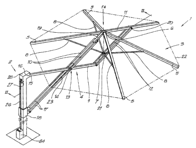
Figure 1 represents a sunshade 1 according to the invention
which mainly consists of a support 2, which in this case is
1o directed upward, and a screen 3 which is fixed to the
support 2 by means of a rod assembly 4.
The above-mentioned screen 3 hereby mainly consists of
bones 5 which are hinge-mounted to each other at one far
end, for example by means of a ring 6, and of a flange 7
which is connected to the bones 5 by means of spokes 8.
The rod assembly 4 in this case consists of four rods 9,
10, 11 and 12 which are hinge-mounted to each other and
which together define a parallelogram, whereby, in this
2o case, the rods 10 and 12 are made double.
Two adjacent rods 9 and 10 of the above-mentioned rod
assembly 4 are connected to each other at an angular
point 13 of the parallelogram by means of a pivot 14,
and they extend as of that angular point 13 up to the
support 2.
The free end 15 of the first of both above-mentioned rods
9 and 10 is connected to the above-mentioned support 2 by
means of a hinge pen 16, whereas the second of the above-
CA 02516014 2005-08-16
mentioned rods 9 and 10 is, in this case, hinge-mounted
to a carriage 18 with its free end 17 which is provided on
the support 2 in a movable manner under the fastening
point of the first rod 9.
5
This second rod 10 in this case forms one of the bones 5 of
the screen 3 and it is fixed to the above-mentioned ring 6
with its other far end 19.
l0 Preferably, also the third rod 11 of the rod assembly 4,
situated opposite to the above-mentioned first rod 9 in the
parallelogram, has a length which is larger than the
length of the side concerned of the parallelogram.
This third rod 11 is, in this case, hinge-mounted to the
above-mentioned second rod 10 by means of the above-
mentioned ring 6 and may be regarded as a bone of the
above-mentioned screen 3.
The fourth rod 12 of the rod assembly 4 is connected to the
third rod 11 with one far end, and it is hinge-mounted
2o to the above-mentioned first arm 9 with its other far end.
To this fourth rod 12, at a distance from the hinge
point 20 between the rods 11 and 12, is fixed the above-
mentioned flange 7 by means of a pivot 21, such that the
fourth rod 12 in this case forms the spoke supporting
the bone which is formed by the above-mentioned third rod
11 of the rod assembly 4.
On the different bones 5 of the screen 3 can be provided a
CA 02516014 2005-08-16
6
canvas 22 which is represented in the figures by means
of a dashed line.
When the above-mentioned first rod 9 serves as a bone,
depending on the size of the canvas 22, a slit 23 will
preferably be provided in this canvas 22 extending at the
height of the above-mentioned first rod 9 as of the place
where the first and second above-mentioned rods 9-10 are
connected to each other up to the addendum line of the
canvas 22.
to
As is represented in figure 2, the above-described
sunshade 1 or the like is preferably provided with means
which make it possible to move the above-mentioned free far
ends 15 and 17 of the first and second rod 9, 10
~15 respectively, in relation to each other on the support 2.
In this case, these means consist of a drive 24 comprising a
cable pulley 25 over which a cable 26 has been wound which is
connected to the above-mentioned carriage 18 with one far
20 end, whereby, depending on the position of the cable
pulley 25, the cable 26 can be guided over one or several
cable wheels 27.
As opposed to the representation in the figures, it is
also possible, of course, to build in the above-
25 mentioned means for moving the free far ends 15 and 17 of
the first and second rod 9, 10 in the support 2, and to
for example conceal the drive 24 in the pipe forming the
vertical support 2.
CA 02516014 2005-08-16
7
It is clear that by the drive 24 is not necessarily meant
a motor drive, but that also a manual drive equipped with
a crank or any other manual operating mechanism is within
the bounds of possibility.
The working of the above-described sunshade 1 or the
like is simple and as follows.
In the folded position of the sunshade 1, as represented in
figure 3, the free far ends 15 and 17 of the first and
1o second rod 9, 10 are situated at a relatively large mutual
distance, in this case at the top and at the foot of the
above-mentioned vertical support 2, whereby the
parallelogram, formed by the rods 9 to 12, extends mainly
vertically, such that the bones which are formed by the
rods 10 and 11, and thus also all the other bones 5, are
folded down, and the screen 3 is in a closed position.
In order to bring the screen 3 from this folded
position into a position of use, it is sufficient to
activate the above-mentioned drive 24 for the cable
pulley 25 in one direction, as a result of which the
carriage 18 and consequently the free far end 17 of
the second rod 10 is moved towards the top 28 of the
vertical support 2, and the distance between the free far
ends 15 and 17 of the above-mentioned first and second
rod 9-10 is reduced.
As a result of this reduction of the above-mentioned
distance, the parallelogram is pushed in a predominantly
horizontal position, as a result of which the screen 3
CA 02516014 2005-08-16
8
moves away from the support 2 and the angle between the
first and the second rod 9-10 of the parallelogram becomes
more acute, such that the screen 3 is unfolded.
In order to put the sunshade 1 or the like away again, it
will suffice to drive the cable pulley 25 in the other
sense or to let the drive 24 run freely, such that the
screen can sag and furl under its own weight.
Depending on the construction and the geometric
characteristics of the sunshade 1 or the like, the screen
1o will not necessarily furl automatically under its own
weight.
In this case can be provided for example a second cable working
in the opposite sense of the first cable 26 and which, when
the drive is activated to put away the screen, pulls the
far end 17 of the rod 10 down.
Although in the figures, the hinge-mounted far end 15
has a fixed position in relation to the support 2 and
the hinge-mounted far end 17 is provided on the support 2
2o in a movable manner, it is not excluded for the other far
end 15 to be movable, whereas the far end 17 is fixed, or
that even both far ends 15-17 are provided in a movable
manner on the support 2.
Further, it is clear that the second and third rod 10-11
of the rod assembly 4 must not necessarily be applied as
bones 5, but that a sunshade 1 or the like according to
the invention can also be realized by connecting at least
CA 02516014 2005-08-16
9
one of the bones 5 to one of the rods 9 to 12 of the
parallelogram, whereas at least one of the spokes 8 is
connected to another rod 9 to 12, preferably an opposite
rod, of the parallelogram. One of the rods 9-10-11-12 can
be made as a bone or vice versa, whereas a second rod can
be made as a spoke, or vice versa.
Finally, figure 5 represents a variant of a sunshade 1 or
the like according to the invention, whereby several
screens 3 are fixed to one support 2 by means of rod
l0 assemblies 4 which are all connected to one or several
carriages 18 on the support 2, whereby in the case of a
single carriage, a common drive 24 can be applied.
The present invention is by no means limited to the above-
described embodiments given as an example and represented
in the accompanying figures; on the contrary, a sunshade or
the like according to the invention can be realized
according to different variants while still remaining within
the scope of the invention.