Note : Les descriptions sont présentées dans la langue officielle dans laquelle elles ont été soumises.
CA 02518941 2005-09-12
PRESSURE-RELIEF VALVE
The invention relates to a pressure-relief valve for
oil-filled transformers and tap changers. When, as a result of
some sort of failure or disturbance, pressure in a casing of a
transformer or in a tap changer exceeds a predetermined limit,
the normally closed pressure-relief valve opens and relieves
pressure in the transformer or tap changer into the surrounding
atmosphere.
Such a pressure-relief valve that is mounted in a port
on the top of a transformer casing is known from US 3,914,528.
It has a circular housing flange that is screwed to the port of
the transformer casing. On the lower face of the housing flange
turned toward the top of the transformer casing there is an
annular seal creating an oil-tight seal. The port of the housing
flange is normally closed by a spring-loaded valve body described
further below. A round downwardly open cupBshaped housing cover
is secured on the housing flange by bolts and screws. The upper
nearly horizontal face of the housing cover has an inner
concentric step. Between the housing cover and the above-
described valve body there are one or more prestressed
compression springs, which are braced upwardly on the inner face
of the housing cover and downwardly on the top face of the valve
body so as to push same down against the housing.flange such that
its port is closed oil-tight. To this end the upper side of the
housing flange turned toward the valve body has an annular seal
ring. If the pressure inside the transformer casing exceeds the
response pressure of the springs, the valve body lifts and allows
pressure equalization; subsequently it is pushed by the springs
again back down on the annular seal on the upperlside of the
housing flange. In addition it is possible with this known
pressure-relief valve to provide on the upper face, outside the
housing cover, optical indicators that can be seen from afar to
- 1 -
CA 02518941 2005-09-12
indicate if the pressure-relief valve has opened. Finally there
are outside the housing cover also electrical monitor contacts or
switches that serve for remote monitoring or indication as well
as to turn off the transformer.
A further highly similar pressure-relief valve is known
from US 4,843,187. It has a particular cross section and special
mounting means for the above-described peripheral seal ring
between the upper face of the housing flange and the lower face
of the valve body.
Another pressure-relief valve is known from US
4,676,266. Here the valve cover is formed as a cup; the
downwardly open side walls fit with another seal that is set in
the annular face of the housing flange. This additional seal has
a flat cross-sectional shape; when closed it is bent to the side
B like a windshield-wiper blade B and seals the valve body at its
side walls additionally against the housing flange. In case of a
problem, when the valve plate rises up because of an overpressure
in the transformer casing, this pressure is effective against the
entire face of the valve body; the force effective on the body
thus is greater and the valve snaps open very fast, inside a few
milliseconds.
All these pressure-relief valves have several
disadvantages. The main one i,s that if there is a problem with
excessive pressure in the transformer casing, when the valve body
is open, the highly pressurized medium is not under control and
can squirt out of the pressure-relief valve. Thzs medium, which
squirts out abruptly and without warning, is extremely hot so
that it poses a substantial risk of burns for nearby personnel,
not to mention fouling the surroundings. A further disadvantage
with the known pressure relief valves is that the switch contacts
are provided without protection outside the actual device, with
no shielding and not protected from UV-rays, ozone, rain, and the
like. In addition they and their cables are exposed to the hot
oil released when the valve opens.
- 2 -
CA 02518941 2005-09-12
A shield for pressure-relief valves is known from WO
98/54498 that is fitted over the valves and that has a relief
port that ensures that any released oil is guided away when the
valve opens. Even this solution has technical problems. To
start with it is a pure retrofit. The shield is mounted on the
pressure-relief valve by means of the existing bolts and screws
that secure the housing cover on the housing flange with the
highly prestressed springs between them. To install the known
shield, these nuts must be loosened, thereby releasing the
spring-loaded housing cover. This runs the risk that the springs
will pop up the housing cover and injure the installer. In
another variant the known shield is secured by an additional
flange adapter with the transformer casing. This is an expensive
variant that not only requires extra parts, but that also creates
seal problems which are dealt with by the provision of further
seals that further complicate the assembly.
It is an object of the invention to provide a pressure-
relief valve of the above-describe type that does not have the
described disadvantages, that is in particular of compact
construction and that, when open, conducts away the hot oil such
that it protects adjacent structure and the surroundings from
being fouled.
This object is achieved by the invention.
With the pressure-relief valve according to the
invention a standard cover is an integral part of the assembly.
That is instead of a separate cover, there is a laterally fully
closed, cup-shaped, upwardly closed housing. This housing is not
mounted like a separate cover according to the prior art in a
complicated manner on the actual pressure-relief valve. It is in
particular not necessary to loosen the spring plate that is
according to the invention underneath the housing. In this
- 3 -
CA 02518941 2005-09-12
manner there is no possibility of accident; at the same time the
possibility of forgetting to properly tighten the spring-cover
plate is avoided in that the spring plate is installed at the
factory; its retaining screws do not need ever to be loosened
later. With the system of this invention there is thus no
adapter that is necessary as in the prior-art systems; thus there
are no additional seal problems. In general, the pressure-relief
valve according to the invention is a compact closed device with
everything held in one housing that can be easily directly
mounted on the transformer casing.
Vent openings are formed on a cup-shaped side wall of
the housing that allow there to be a controlled venting in case
of accident. These vent openings can be dimensioned variously;
according to a particular flow cross section one can avoid
unwanted flow restriction while at the same time the oil flow can
be controlled and its flow can be broken up. The provision of a
plurality of small rather than a single large vent opening
ensures in the simplest manner possible that a finger or foreign
body cannot get inside the assembly. It is also possible to
provide horizontal vent slots with each having an overhead shield
hood. By providing the vent holes in the generally vertical side
wall one gets good rain or drip protection. The cup-shaped
housing also protects any eventually used switch~contacts. By
the provision of cable feedthroughs on a feedthrough plate
according to a further preferred embodiment of the invention the
cables can be protected against high strains; these additional
cable feedthroughs withstand most of the tension in the cables
and thus relieve the connections to the electrical terminals
almost completely. In addition the described cables are
protected from the hot oil in that the pressure-relief valve
according to the invention has a defined oil outflow region that
is partitioned off from that of the cable feedthroughs. This
prevents the hot oil from directly contacting and damaging the
cables.
- 4 -
CA 02518941 2005-09-12
The invention is described in the following by way of
example with reference to the drawings. Therein
FIG. 1 is a first pressure-relief valve according to
the invention in a closed (rest) position in a lateral schematic
sectional view;
FIG. 2 is this pressure-relief valve in the open
position relieving pressure in the same section but 90Eoffset
horizontally;
FIG. 3 is this pressure-relief valve seen from outside
in perspective view;
FIG. 4 is a second pressure-relief valve according to
the invention in closed (rest) position in a lateral schematic
sectional view;
FIG. 5 is this pressure-relief valve in the open
position relieving pressure in the same section but 90Eoffset
horizontally;
FIG. 6 is this pressure-relief valve seen from outside
in perspective view;
FIG. 7 is a detail view of a seal of this pressure-
relief valve;
FIG. 8 is an enlarged view of this seal;
FIG. 9 is a third pressure-relief valve according to
the invention partly in lateral section;
FIG. 10 is a fourth pressure-relief valve according to
the invention, again in a detail lateral section.
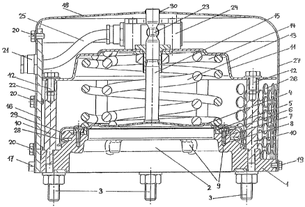
With reference at first to FIG. 1, the primary elements
of a first pressure-relief valve according to the invention are
described. It has a housing flange 1 that is made of cast iron
and defines a throughgoing port 2. This housing flange 1 is
secured to an unillustrated transformer casing in the standard
manner by a circular array of mounting screws 3. A valve body 4
upwardly closes the port 2 of the flange 1 in the known manner.
- 5 -
CA 02518941 2005-09-12
To ensure oil tightness, there is an L-section seal ring 5 that
is secured in place on the housing flange 1 by a retaining ring 6
and an annular array of screws 7. To this end there are threaded
bores 8 on reinforcement ribs 9 of the housing flange 1, in which
the screws 7 are threaded so that the retaining ring solidly
holds the seal ring 5. In addition bolts 10 with internal
screwthreads are screwed into the housing flange 1 and extend
vertically upward therefrom. A spring plate 11 acting like the
housing cover in the prior art is secured by screws 12 that are
threaded down into the internal screwthreads of the bolts 10.
Between the spring plate 11 and the valve body 4 there are the
standard two prestressed springs, namely an inner spring 13 and
an outer spring 14. Both the inner spring 13 and the outer
spring 14 are upwardly braced at concentric locations on the
lower face of the spring plate 11; their upper (translator's
note, should be "lower") ends bear on the valve body 4 which has
a complementary concentrically stepped shape. In the center of
the valve body 4 there is an indicator pin 15 that projects
vertically upward. The housing flange 1 carries on one side an
upright feedthrough plate 16 with mounting screws 17 that is
described more closely below. The entire assembly is contained
in a cup-shaped housing 18 that is secured by screws 19 on the
housing flange 1 and by further screws 20 on the feed-through
plate 16. The feedthrough plate 16 has several cable
feedthroughs 21; to allow the housing 18 to be mounted, it has a
lateral opening 22 that slips downward during assembly over the
cable feedthroughs 21. The indicating pin 15 has in its upper
end region inside the assembly a switching cam 23 that coacts
with one or more switches 24, a roller or limit switch. Cables
25 from these switches 24 extend outward through the cable
feedthroughs 21. On the side of the housing 18 opposite the
cable feedthroughs 21 there are outlet openings 26 that are
formed in a vertical and downwardly extending side wall 27. In
the illustrated embodiment they are a number of small bores that
- 6 -
CA 02518941 2005-09-12
each have a diameter at most equal to 12 mm although it is
possible as stated above for them to have numerous other shapes
or sizes within the scope of the invention. Finally there is
another seal 28 formed as a seal lip as in US 4,676,266 to act
like a windshield wiper and that fits in a downwardly bent cup-
shaped wall 29 of the valve body 4. This additional seal 28 is
not essential to the pressure-relief valve but serves merely to
prevent a fluttering of the valve and to increase its opening
speed. Finally the indicating pin 15 projects through an opening
30 in the top of the housing 18, that is to the outside.
FIG. 2 shows the same assembly rotated through 90E
about a vertical axis but in the open position. It can be seen
that when there is an overpressure in the unillustrated
transformer casing the valve body 4 is pushed upward against the
force of the springs 13 and 14. In this position the valve body
4 no longer engages the seal 5; the seal 28 however is also
disengaged from the side wall 29 of the valve body 4. Excess hot
liquid and gas thus enter into the pressure-relief valve and flow
out through the holes 26. The indicating pin 15 rises with the
valve body 4. Its cam formation 23 operates the electrical
switch 24. It is also possible that the now outwardly projecting
end of the indicating pin 15 can be used to actuate another here
not illustrated indicator. The spring plate 11 ensures that the
space that the oil can fill is upwardly closed. The hot mass of
oil cannot get to the switch 24 or its cables 25 to damage them.
Once the overpressure is relieved, the springs 13 and 14 will
return the valve body 4 to its rest position; the seals 5 and 28
seal the valve body with respect to the port 2.
FIG. 3 shows the entire assembly in perspective view.
It is clear that the housing 18 completely contains all parts.
It can further be seen that to secure it on a transformer casing
no further adapter is needed, not even when during the service
life of the assembly the spring-loaded spring plate must be
removed. Finally it is clear that this device has no electrical
_ 7 _
CA 02518941 2005-09-12
switches or connections that could be damaged outside the
housing.
FIGS. 4 to 6 show the principal elements of a second
different embodiment of the pressure-relief valve according to
the invention. Identical parts are assigned the,same references;
the basic structure corresponds to that of the first embodiment.
Unlike the above-described first embodiment described with
reference to FIGS. 1 to 3, here a transformer cover 31 is shown
that has a port 32 to which the pressure-relief valve with the
housing flange 1 and the central port 2 are secured. In this
embodiment the indicator pin 15 carries on its upper end that
projects out of the housing 18 a mushroom-shaped head 33. This
mushroom head 33 protects the entire pressure-relief valve and
also the switch 24 from the entry of rain water. It can also
have an additional seal not shown here. The mushroom head 33 is
preferably secured from above by a mounting screw 34 on the
indicator pin 1. In this embodiment there are, instead of
circular outlet holes, vent slots 35, 36, and 37 that extend
radially (translator's note: should be "angularly") in offset
horizontal planes in the cup-shaped side wall 27 of the housing
18. From outside there are vent hoods 38, 39, 40 that prevent
rain from entering into the vent slots 35, 36, and 37 by
shielding them from above. This embodiment also ensures that
neither fingers or other foreign bodies can get inside. The vent
hoods 38, 39, and 40 can also be formed as separate elements
applied externally to the housing 18. Finally in this embodiment
there are also stiffening ribs 41 in the upper horizontal part of
the housing so as to make this housing 18 very stiff.
The switch 24 can be mounted preferably by threaded
stud assemblies 42, 43 projecting upward from the spring plate
11. This makes it simple to install one or several switches 24
from above without having to remove other parts outside the
housing 18. Preferably enough stud subassemblies 42, 43 are
provided in particular locations that the maximum number of
_ g _
CA 02518941 2005-09-12
switches 24 can be installed. If only or a few or no switches
are needed, the unused studs remain free. It would also be
possible as known in the prior art to mount the switch from above
by screws threaded directly into the spring plate 11. The
disadvantage of this is that the spring plate ll is relatively
thin so that the screwthreads could tear out; this disadvantage
is avoided according to the proposed mounting by means of inset
threaded stud assemblies 42, 43.
FIGS. 7 and 8 show the already described L-section seal
5. A leg 5.1 of this seal 5 projects upward against the valve
body 4 and seals the port 2. In a particularly advantageous
embodiment, a seal face 5.2, that in the rest position bears on
the valve body 4, is beveled, e.g. by 15E. In this manner the
effective seal surface is reduced and the specific biasing
pressure is increased, which is particularly important for low
reaction pressures, e.g. 8 PSI. in addition this beveling
facilitates the fit of the seal face 5.2 on any unavoidable
irregularities of the valve body 4.
FIG. 9 shows a detail of a further pressure-relief
valve according to the invention with a particularly advantageous
system for securing the housing 18 directly to the housing flange
1. Whereas in the above-described embodiments, mounting is
effected by horizontal bolting here pusher pins 44 fitting in
bores 45 of the housing flange 1 are provided, with their outer
ends spring biased outward through corresponding holes in the
cup-shaped side wall 27 of the housing 18. This spring loading
of the pins 44 is the job of respective springs 46 braced between
inner ends of the pins 44 and floors of the bores 45. Each pin
44 is provided with a radially outwardly projecting stop shoulder
47 on its cylindrical outer surface that is engaged against a
stop sleeve 48 screwed into the housing flange 1. The outer end
of each pin 44 is spherically rounded to facilitate sliding of
the side wall 27 of the housing 18 into place. The rounded ends
of the pins 44 engage outward in assembled condition through the
- 9 -
CA 02518941 2005-09-12
corresponding openings; for disassembly they are pushed inward
against the force of their springs 46 and the housing 18 is
lifted off. This embodiment makes it possible to install and
remove the housing 18 without the use of tools, while still
securing this housing 18 directly to the flange 1.
FIG. 10 finally shows a further detail of a
particularly advantageous further developed pressure-relief valve
according to the invention with venting. When mounted
horizontally it is possible that gas builds up inside the
pressure-relief valve, so that there needs to be some special
venting. To this end there is a vent passage 49 that extends
through the housing flange 1 to a conical seat 5 at the end of a
horizontal, outwardly extending threaded bore 51: A vent screw
52 is threaded from outside into this threaded bore 51 and bears
at its inner end against the seat 50. The seat 50 of the
threaded bore is dimensioned relative to the end of the vent
screw 52 such that when it is screwed tight, the vent screw 52
completely closes the vent passage 49 without the use of any seal
ring as in the prior art. It is particularly advantageous when
the vent screw 52 is formed with a central vent bore 53 that is
closed in the closed position of the vent screw 52. In this
manner the pressure-relief valve can be vented by partially
screwing out and loosening the vent screw 52, after which it is
again screwed tight.
- 10 -