Sélection de la langue

Search

Sommaire du brevet 2523314 

Énoncé de désistement de responsabilité concernant l'information provenant de tiers

Une partie des informations de ce site Web a été fournie par des sources externes. Le gouvernement du Canada n'assume aucune responsabilité concernant la précision, l'actualité ou la fiabilité des informations fournies par les sources externes. Les utilisateurs qui désirent employer cette information devraient consulter directement la source des informations. Le contenu fourni par les sources externes n'est pas assujetti aux exigences sur les langues officielles, la protection des renseignements personnels et l'accessibilité.

Disponibilité de l'Abrégé et des Revendications

L'apparition de différences dans le texte et l'image des Revendications et de l'Abrégé dépend du moment auquel le document est publié. Les textes des Revendications et de l'Abrégé sont affichés :

  • lorsque la demande peut être examinée par le public;
  • lorsque le brevet est émis (délivrance).
(12) Demande de brevet: (11) CA 2523314
(54) Titre français: NIVEAU AVEC DISPOSITIFS DE REPERAGE DE FIXATIONS REGLABLES
(54) Titre anglais: LEVEL WITH ADJUSTABLE FASTENER LOCATORS
Statut: Morte
Données bibliographiques
(51) Classification internationale des brevets (CIB):
  • G01C 9/02 (2006.01)
  • G01C 9/28 (2006.01)
  • G01C 9/34 (2006.01)
(72) Inventeurs :
  • SCHMIDT, WILLIAM (Etats-Unis d'Amérique)
  • FISHER, KATHLEEN (Etats-Unis d'Amérique)
  • DEBOER, JEFFREY A. (Etats-Unis d'Amérique)
  • NELLENBACK, MICHAEL (Etats-Unis d'Amérique)
(73) Titulaires :
  • THE FAUCET QUEENS, INC. (Etats-Unis d'Amérique)
(71) Demandeurs :
  • THE FAUCET QUEENS, INC. (Etats-Unis d'Amérique)
(74) Agent: GOWLING LAFLEUR HENDERSON LLP
(74) Co-agent:
(45) Délivré:
(22) Date de dépôt: 2005-10-14
(41) Mise à la disponibilité du public: 2006-05-18
Requête d'examen: 2007-11-30
Licence disponible: S.O.
(25) Langue des documents déposés: Anglais

Traité de coopération en matière de brevets (PCT): Non

(30) Données de priorité de la demande:
Numéro de la demande Pays / territoire Date
10/992,392 Etats-Unis d'Amérique 2004-11-18

Abrégés

Abrégé anglais


A level assembly includes a housing having a level mounted within. The
housing includes a first arm and a second arm slidably attached to the
housing. The
first and second arms are both stored in storage positions. Fastener locators
associated with each arm are both stored in storage positions. During use the
fastener locators are pivoted to an extended position. If additional distance
between
the fastener locators is needed the first and second arms can also be extended
by
sliding them along another axis relative to the housing.

Revendications

Note : Les revendications sont présentées dans la langue officielle dans laquelle elles ont été soumises.


CLAIMS


1. A level assembly comprising:
a housing which defines a first axis;
a level mounted within said housing;
a first arm moveable relative to said housing along said first axis; and
a first fastener locator movable relative to said first arm.

2. The assembly of claim 1, wherein said first arm is slidably mounted to said
housing.

3. The assembly of claim 1, wherein an interface between said housing and said
first arm is a tongue and groove.

4. The assembly of claim 1, wherein said first fastener locator defines a
keyhole
aperture.

5. The assembly of claim 1, wherein said first axis is defined by an interface
between said first arm and said housing.

6. The assembly of claim 6, wherein said first arm is slidable along said
first
axis relative to said housing.

7. The assembly claim 1, wherein said first fastener locator is moveable along
a
second axis parallel to said first axis.

8. The assembly of claim 7, wherein said second axis is defined by said first
arm.

9. The assembly of claim 7, wherein said first fastener locator pivots about
said
second axis.


6


10. The assembly claim 9, wherein said first fastener locator pivots about
said
second axis between an extended and storage position.

11. The assembly of claim 12, wherein said retracted position is parallel to
said
first arm and said extended position is perpendicular to said first arm.

12. The assembly of claim 11, wherein said first arm defines a recess to
receive
said fastener locator in said storage position.

13. The assembly of claim 1, further including a second arm moveable relative
to
said housing along said first axis.

14. A level assembly comprising:
a level mounted within a housing defining a first axis;
a first arm moveable relative to said housing along said first axis;
a first fastener locator movable along a second axis parallel to said first
axis;
a second arm moveable relative to said housing along said first axis; and
a second fastener locator moveable along said second axis.

15. The assembly of claim 14, wherein said first arm and said second arm move
independently from one another.

16. The assembly of claim 14, wherein said first fastener locator is slidably
mounted to said first arm and said second fastener locator is slidably mounted
to
said second arm.

17. The assembly of claim 14, wherein said first fastener locator and said
second
fastener locator pivot about said second axis.


7

Description

Note : Les descriptions sont présentées dans la langue officielle dans laquelle elles ont été soumises.

CA 02523314 2005-10-14
LEVEL WITH ADJUSTABLE FASTENER LOCATORS
BACKGROUND OF THE INVENTION
The present invention is a level and more particularly a level having slidable
arms with adjustable fastener locators for simultaneously designating a
multiple of
fastener locations.
In order to hang an object on a wall, all of the locations for the fasteners
that
mount the object must be precisely marked. Various devices that assist in
marking
the fastener positions are known. Conventional devices include levels that
have
indicators for marking the distance between the fasteners. However,
simultaneously
marking a multiple fastener locations in a level position and at a desired
separation
distance may be relatively difficult utilizing conventional level devices.
Conventional level devices that mark multiple locations at one time may be
relatively large and awkward devices. These conventional level devices may be
difficult and inconvenient to store and use for most common household tasks.
Thus, a compact device that assists in hanging and leveling objects that use
multiple fasteners is needed.
SUMMARY OF THE INVENTION
The present invention provides a level assembly including a housing having
a level mounted within. A first arm and a second arm interface with the
housing
along a first axis. The first arm and the second arm are slidably attached to
the
housing to move along the first axis relative to the housing. Each arm has a
fastener
locator that is aligned with a corresponding fastener on the picture or
object. The
fastener locators are then used to locate the appropriate position for the
fasteners on
the wall.
The fastener locators are mounted to the arms to pivot about a second axis
between a storage position and an extended position. The fastener locators
each
have an aperture to guide a marking device to pass through for marking a
fastener
location when hanging an object.
In use, the fastener locators are pivoted to an extended position. Each arm
has a groove in which the fastener locators are slidably retained. The groove
is
1

CA 02523314 2005-10-14
located along a second axis such that the fastener locators slide along the
second
axis. Each fastener locator is slidable along the second axis until the
desired spacing
between the fastener locators is obtained. To mark relatively greater
distances
between fasteners the first and second arms are be extended by sliding them
along
the first axis relative to the housing. For storage the arms are retracted and
the
fastener locators are returned to the storage positions.
BRIEF DESCRIPTION OF THE DRAWINGS
The various features and advantages of this invention will become apparent
to those skilled in the art from the following detailed description of the
currently
preferred embodiment. The drawings that accompany the detailed description can
be briefly described as follows:
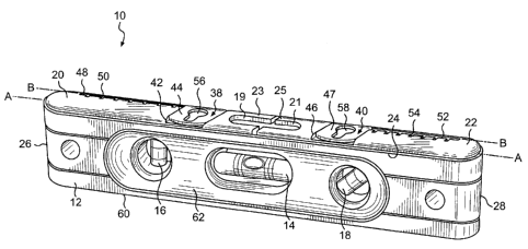
Figure 1 is a general view of the leveling device of the present invention;
Figure 2 is a perspective view of one embodiment showing the interface
between the first arm and the housing of the leveling device;
Figure 3 is a view of the top side of the leveling device of the present
invention;
Figure 4 is a general view of the leveling device where the fastener locators
are in an extended position; and
Figure S is a general view of one embodiment of the leveling device where
the arms and fastener locators are in extended positions.
DETAILED DESCRIPTION OF THE PREFERRED EMBODIMENT
Figure 1 illustrates a level assembly 10 which includes a housing 12 that
defines a first axis A. Mounted within the housing 12 is a level 14. The level
14 is a
parallel to the first axis A. Additional levels 16 and 18 may correspond to
other axes
such as an axis perpendicular to the first axis A.
The level assembly includes a first arm 20 and a second arm 22. The first
arm is located on a top side 24, adjacent a first end 26 of the level assembly
10. The
second arm 22 is also located on the top side 24 of the level assembly 10. The
second arm 22 is located adjacent a second end 28. When in a retracted
position the
2

CA 02523314 2005-10-14
first arm 20 preferably does not extend beyond the first end 26. Likewise,
when in a
retracted position the second arm 22 does not extend beyond the second end 28.
The first arm 20 and the second arm 22 interface with the housing 12 along
the first axis A. The first arm 20 is attached to the housing 12 such that the
first arm
20 is moveable relative to the housing 12 along the first axis A.
Figure 2 shows one embodiment of the first arm 20 where the interface is a
groove 30 formed in the housing 12. The groove 30 defines the first axis A. A
first
tongue 32 extends from the first arm 20. The first tongue 32 fits within the
groove
30 such that the first tongue 32 can slide within the groove 30. Applying
force to
the first arm 20 causes the first tongue 32 to slide within the groove 30 and
the first
arm 20 to move relative to the housing 12. An indentation 19 adjacent to a
center
section 23 of the first arm 20 allows for axial force to be applied to the
first arm 20
along the first axis A. The second arm 22 is attached in a similar manner such
that it
is movable along the first axis A relative to the housing 12.
The second arm 22 includes a second tongue 34 similar to the first tongue 32.
The second tongue 34 corresponds to groove 36 in the housing 12. An
indentation
21 adjacent to a center section 25 of the second arm 22 allows for axial force
to be
applied to the second arm 22 along the first axis A. Additionally, the
indentations
19 and 21 allow the level 14 to be seen from the top of the housing 12. Other
types
of interfaces that permit the first arm 20 and the second arm 22 to move
relative to
the housing 12 may additionally or alternatively be used. In this embodiment,
the
first arm 20 and the second arm 22 slide between a storage position and an
extended
position (Figure 5).
The first arm 20 includes a first fastener locator 38. The second arm 22
includes a second fastener locator 40. The first fastener locator 38 and
second
fastener locator 40 are movable between storage positions (Figure 1) and
extended
positions (Figure 5). The first fastener locator 38 fits within a first recess
42 defined
in the first arm 20 such that a first side 44 of the first fastener locator 38
is relatively
level with the first arm 20. When in the storage position the second fastener
locator
40 fits within a second recess 46 defined in the second arm 22 such that a
first side
47 of the second fastener locator 40 is relatively with the second arm 22. The
first
recess is formed by a separation between the first arm 20 and the center
section 23.
3

CA 02523314 2005-10-14
Likewise the second recess 46 is formed by a separation between the second arm
22
and the second center section 25.
The first arm 20 has a first groove 48 in which the first fastener locator 38
is
slideably retained. The first groove 48 defines the second axis B along which
the
first fastener locator 38 is slidable. The second axis B is parallel to the
first axis A.
The first fastener locator 38 has an engagement member 39 that corresponds to
the
groove 48. The engagement member 39 has a cylindrical shape such that the
first
fastener locator 38 is slidably and rotatably retained within the groove 48.
The
cylindrical shape of the engagement member 39 permits the first fastener
locator 38
to pivot about a second axis B between the storage and extended position and
to
slide within the groove 48. The groove 48 has a first set of indentations 50
for
marking preset distance locations of the first fastener locator 38. It should
be
understood that other indicia may be utilized.
The second arm 22 has a second groove 52 in which the second fastener
locator 40 is slidably retained in a similar manner. The second groove 52 has
a
second set of indentions 54 marking preset distance locations of the second
fastener
locator 40. The second groove 52 is parallel with the first groove 48 such
that the
second fastener locator 40 is slidable along the second axis B.
Figure 3 illustrates a top view of the level assembly 10 in a storage
position.
The first fastener locator 38 defines a first aperture 56 and the second
fastener
locator 40 defines a second aperture 58. In this embodiment both apertures
have a
keyhole shape. The first aperture 56 and second aperture 58 allow a marking
device
to pass through for marking a fastener location when hanging an object.
Referring to Figure 4 the first fastener locator 38 and the second fastener
locator 40 are mounted to pivot about the second axis B between a storage
position
and an extended position (Figure 5). The first recess 42 in the first arm 20
defines a
storage position for the first fastener locator 38 and the second recess 46 in
the
second arm 22 defines a storage position for the second fastener locator 40.
When
in the extended position, the first fastener locator 38 is slidable within the
first
groove 48 along the second axis B, illustrated by reference arrow E-E (Figure
5).
The first set of indentations 50 assist in locating the desired position of
the first
fastener locater. Likewise, the second fastener locator 38 operates relative
to the
4

CA 02523314 2005-10-14
second arm 22, illustrated by reference arrows F-F. The second fastener
locator 40
is slidable within the second groove 52 to the desired marking positions and
the
second set of indentations 54 assist in locating the desired position of the
second
fastener locator. To obtain greater distance between the fastener locaters 38,
40 the
first arm 20 and the second arm 22 are slidable along the first axis A (Arrows
C-C
and arrows D-D; Figure 5).
Although a preferred embodiment of this invention has been disclosed, a
worker of ordinary skill in this art would recognize that certain
modifications would
come within the scope of this invention. For that reason, the following claims
should be studied to determine the true scope and content of this invention.
5

Dessin représentatif
Une figure unique qui représente un dessin illustrant l'invention.
États administratifs

Pour une meilleure compréhension de l'état de la demande ou brevet qui figure sur cette page, la rubrique Mise en garde , et les descriptions de Brevet , États administratifs , Taxes périodiques et Historique des paiements devraient être consultées.

États administratifs

Titre Date
Date de délivrance prévu Non disponible
(22) Dépôt 2005-10-14
(41) Mise à la disponibilité du public 2006-05-18
Requête d'examen 2007-11-30
Demande morte 2012-10-15

Historique d'abandonnement

Date d'abandonnement Raison Reinstatement Date
2011-10-07 R30(2) - Absence de réponse
2011-10-14 Taxe périodique sur la demande impayée

Historique des paiements

Type de taxes Anniversaire Échéance Montant payé Date payée
Enregistrement de documents 100,00 $ 2005-10-14
Le dépôt d'une demande de brevet 400,00 $ 2005-10-14
Taxe de maintien en état - Demande - nouvelle loi 2 2007-10-15 100,00 $ 2007-08-31
Requête d'examen 800,00 $ 2007-11-30
Taxe de maintien en état - Demande - nouvelle loi 3 2008-10-14 100,00 $ 2008-09-11
Taxe de maintien en état - Demande - nouvelle loi 4 2009-10-14 100,00 $ 2009-09-17
Taxe de maintien en état - Demande - nouvelle loi 5 2010-10-14 200,00 $ 2010-09-30
Titulaires au dossier

Les titulaires actuels et antérieures au dossier sont affichés en ordre alphabétique.

Titulaires actuels au dossier
THE FAUCET QUEENS, INC.
Titulaires antérieures au dossier
DEBOER, JEFFREY A.
FISHER, KATHLEEN
NELLENBACK, MICHAEL
SCHMIDT, WILLIAM
Les propriétaires antérieurs qui ne figurent pas dans la liste des « Propriétaires au dossier » apparaîtront dans d'autres documents au dossier.
Documents

Pour visionner les fichiers sélectionnés, entrer le code reCAPTCHA :


Pour visualiser une image, cliquer sur un lien dans la colonne description du document. Pour télécharger l'image (les images), cliquer l'une ou plusieurs cases à cocher dans la première colonne et ensuite cliquer sur le bouton "Télécharger sélection en format PDF (archive Zip)" ou le bouton "Télécharger sélection (en un fichier PDF fusionné)".

Liste des documents de brevet publiés et non publiés sur la BDBC .

Si vous avez des difficultés à accéder au contenu, veuillez communiquer avec le Centre de services à la clientèle au 1-866-997-1936, ou envoyer un courriel au Centre de service à la clientèle de l'OPIC.


Description du
Document 
Date
(yyyy-mm-dd) 
Nombre de pages   Taille de l'image (Ko) 
Description 2005-10-14 5 228
Abrégé 2005-10-14 1 15
Dessins 2005-10-14 5 111
Revendications 2005-10-14 2 56
Page couverture 2006-05-10 1 48
Dessins représentatifs 2006-04-21 1 20
Revendications 2010-07-23 2 51
Cession 2005-10-14 9 292
Taxes 2009-09-17 1 40
Taxes 2007-08-31 1 41
Poursuite-Amendment 2007-11-30 2 47
Poursuite-Amendment 2008-02-22 1 33
Poursuite-Amendment 2008-04-17 2 70
Taxes 2008-09-11 1 39
Poursuite-Amendment 2010-01-26 2 61
Poursuite-Amendment 2010-07-23 5 174
Taxes 2010-09-30 1 45
Poursuite-Amendment 2011-04-07 2 70