Note : Les descriptions sont présentées dans la langue officielle dans laquelle elles ont été soumises.
CA 02523845 2005-10-19
VARIABLE FOCAL DISTANCE IMAGE READER
FIELD OF INVENTION
[0001 ] The field of the invention directed to image readers and in particular
to an
image reader providing variable focal distance.
BACKGROUND OF THE INVENTION
[0002] Digital imaging technology continues to improve and find widespread
acceptance in both consumer and industrial applications. Digital imaging
readers are
now commonplace in video movie cameras, security cameras, video teleconference
cameras, machine vision cameras and, more recently, hand-held bar code
readers. As
each application matures, the need for intelligent image processing techniques
grows.
To date, the large data volume attendant to transmitting a digital image from
one
location to another could only be accomplished if the two locations were
connected by
a wired means. Machine vision and imaging-based automatic identification
applications required significant computing power to be effective and
correspondingly
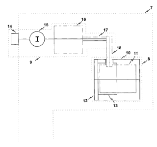
require too much electricity to be useful in portable applications. The trend
now in
both consumer and industrial markets is toward the use of portable wireless
imaging
that incorporates automatic identification technology.
[0003] Historically, the automatic identification industry has relied on laser
technology as the means for reading bar codes. Laser scanners generate a
coherent
light beam that is oriented by the operator to traverse the horizontal length
of the bar
code. The reflected intensity of the laser beam is used to extract the width
information
from the bars and spaces that are encountered. Laser scanners are effective in
reading
linear bar codes such as the U.P.C. code found in retail point-of sale
applications,
Code 39, Interleaved 2 of 5, or the like. Information stored in these linear
(1D) bar
codes is used to represent a short message or an index number related to a
separate
data file located in a central computer.
-1-
CA 02523845 2005-10-19
[0004] Imaging-based scanners use a solid-state image sensor such as a Charge
Coupled Device (CCD) or a Complimentary Metal Oxide Semiconductor (CMOS)
imager to convert an image scene into a collection of electronic signals. The
image
signals are processed so that any machine-readable character or bar code found
in the
S field of view can be located in the electronic representation of the image
and
subsequently interpreted. The ability of image-based readers to capture an
electronic
image of a two-dimensional area for later processing makes them well suited
for
decoding all forms of machine-readable symbology at any orientation.
[0005] An image-based scanner is made up of an optical imaging chip, light-
emitting
diodes (LEDs), a lens, a targeting means and other optical components such as
wedges
or diffusers. The lens is attached to the module housing by a threaded
assembly
which, when tightened and locked, holds the lens at a specific fixed distance
above the
imaging array. An illumination board contains the LEDs and targeting means for
aiming the target symbology. The lens projects through an aperture in the
illumination board which is also held in place by the module housing.
[0006] Generally, there are different types of cameras to image different
types of
symbology. They include ultra high definition (UHD), high definition (HD),
standard
(ST) and ultra long range (ULR). These cameras have a different focal distance
for
each of these different applications. This means that the lens is at a
different distances
from the imager in each of these cameras in order to provide the different
focal ranges.
[0007] The distance between the imaging array and the lens determines the
focal
range of the camera module. Generally, this distance is calibrated and then
fixed
within the module assembly. To have an auto-focusing system, similar to those
found
in regular cameras would greatly impact the size and cost, making it an
impractical
feature for camera modules of the type found in image readers. Therefore, it
is
necessary to configure a separate camera module to accommodate the focal range
of
different symbology feature sizes. It is possible to use a multi-focus lens,
which could
take images of multiple symbols of different feature size, however this method
limits
the field of view of each symbol imaged thereby degrading the quality of the
image.
-2-
CA 02523845 2005-10-19
[0008] US Patent Number 5,814,803, which issued to Olmstead et al on September
29, 1998 and US Patent Number 6,073,851, which issued to Olmstead et al on
June
13, 2000 describe a multi-focus technique whereby a single camera module can
image
multiple symbologies at different focal ranges simultaneously. Since the lens
is
simultaneously taking the image of multiple symbologies, the field of view for
each
symbol is limited.
[0009] US Patent Number 5,756,981, which issued to Roustaei et al on May 26,
1998,
describes a technique used in a camera module having a lens assembly that
contains
multiple lenses. The lenses are moved apart in relation to each other by a
solenoid or
motor. This allows the camera to image the symbology at different focal
ranges.
This technique however, is limited to a more expensive camera module with a
multi-
lens optical assembly, and would not be useful in single lens camera modules.
[0010] Further, US Patent 6,340,114, which issued to Correa et al on January
22,
2002, describes a technique in which the lens assembly comprises 2 lenses each
having a different focal range. A moving optical element such as a mirror is
provided
to select an image through either the first or second lens. This technique
however, is
quite complex and requires numerous extra features including dedicated
mirrors, an
extra lens and mechanical means such as an electronic servo mechanism to
control the
mirrors. These extra features would make this technique expensive and
impractical
for a variety of imaging applications such as image readers and barcode
readers.
[0011 ] Presently, cameras either provide a single focal range, or provide
multiple
focal ranges at the expense of limited field of view (FOV) and lowered
definition
quality, these lenses usually must share the FOV with more than one symbol and
sometimes with more than one lens.
[0012] Therefore there is a need for a camera that could accommodate more than
just
a single focal range while maintaining the same FOV and definition quality.
SUMMARY OF THE INVENTION
[0013] The present invention is directed to a variable focal distance image
reader
comprising a lens for focusing a target on an image sensor, and an electro-
mechanical
-3-
CA 02523845 2005-10-19
system for moving the lens between at least two predetermined lens positions
wherein
each of the predetermined lens positions corresponds to a unique focal
distance.
[0014] In accordance with a specific aspect of the invention, the lens is a
single,
cylindrical lens.
[0015] In accordance with another aspect of the invention, the electro-
mechanical
system comprises a solenoid having a coil and a plunger coupled to the lens, a
current
source for driving the solenoid and a control interface for controlling the
current
source. The plunger may be coupled to the lens by a lever.
[0016] In accordance with yet another aspect of the invention, the
predetermined lens
positions correspond to the focal distances required for two or more of the
applications, which may include ultra high definition (UHD), high definition
(HD),
standard (ST) and ultra long range (ULR).
[0017] Other aspects and advantages of the invention, as well as the structure
and
operation of various embodiments of the invention, will become apparent to
those
ordinarily skilled in the art upon review of the following description of the
invention
in conjunction with the accompanying drawings.
BRIEF DESCRIPTION OF THE DRAWINGS
[0018] The invention will be described with reference to the accompanying
drawings,
wherein:
Figures la and 1b illustrate two examples of focal distances required for
particular
applications and;
Figure 2 is side view of a schematic of the present invention shown within a
barcode
scanner.
DETAILED DESCRIPTION
[0019] For purposes of explanation, a specific embodiment is set forth to
provide a
thorough understanding of the present invention. However, it will be
understood by
one skilled in the art, from reading this disclosure, that the invention may
be practiced
-4-
CA 02523845 2005-10-19
without these specific details. Moreover, well-known elements, devices,
process steps
and the like are not set forth in detail in order to avoid obscuring the scope
of the
invention described.
[0020] The present invention will be described with reference to the drawings
where
identical numerals represent similar elements throughout.
[0021 ] Different imaging applications require different focal distances. The
focal
distance is dependent on the type of lens used in the camera module. In
general, the
focal distance is calibrated and then fixed within the module assembly.
Figures 1 a and
1b show two examples of focal distances required for particular applications.
Figure
1 a shows the focal distance required for ST applications. In this instance,
the distance
between the lens 2 and the ST target 4, a barcode on a grocery item for
example, is
160 mm. Figure 1b shows the focal distance required for ULR applications. In
this
instance, the distance between the Iens 2 and the ULR target 6, a barcode on
an over-
sized parcel or crate for example, is 293 mm.
[0022] The present invention comprises an electro-mechanical device for moving
the
lens between at least two different predetermined lens positions which would
allow
the camera to image symbols with different feature sizes. A camera module
having a
single lens can be used to image symbols requiring an ultra high definition
setting,
wherein the symbology feature size is very small, and then, the same camera
module
can also be used to image standard type symbology such as 2D barcodes by
changing
the position of the lens. This invention eliminates the need of requiring up
to four
different camera modules for various features sizes of symbology.
[0023] An embodiment of the present invention is shown in figure 2. An image
reader, such as a barcode scanner 7 comprises an imager module 8 and an
electro-
mechanical system 9.
[0024] The imager module 8 comprises a module housing 10, a cylindrical
objective
lens 11 and an image board 12. The module housing 10 is basically a hollowed
out
shape that is used to enclose the components of the imager in a stable and
rigid
fashion. It is preferably constructed from some form of molded plastic. Its
primary
purpose is to provide rigidity to the structure, as well as to shade the image
sensor
-S-
CA 02523845 2005-10-19
from external light sources. Module housing 10 further includes a base 13,
which acts
to support the lens 11 as well as to shroud light from the image sensor, which
is
attached to the inner surface of the image board 12. The image board 12
contains
some circuitry associated with the image sensor (not shown). Both housing 10
and
lens 11 include holes bored into their top surface to engage with the electro-
mechanical system 9.
[0025] The cylindrical objective lens 11, is a common component in the
industry, a
person skilled in the art would select an objective lens of the appropriate
type
depending on the camera application.
[0026] The image board 12 is generally a printed circuit board that provides
connectivity for the electronic components as well as a physical surface with
which to
provide mechanical stability. A person skilled in the art could envision the
use of
another surface to provide the mechanical stability and to provide the
components
with electrical conductivity.
[0027] The electro-mechanical system 9 comprises a control interface 14, a
current
source 15 and a solenoid 16 having a plunger 17 connected to a lever 18.
Current
source 15 supplies solenoid 16 with current. Depending on the type of solenoid
used,
either a pull or push type, the moving plunger 17 within the solenoid 16
either pulls or
pushes lever 18. Lever 18 mates with holes bored into the top surfaces of
housing 12
and objective lens 11. Since lever 18 mates with a hole within objective tens
11, the
pulling/pushing action of lever 18, pulls or pushes lens 11. The degree to
which
objective lens 11 is pulled or pushed is dependent on the magnetic force of
solenoid
16, which is in turn dependent on current source 15. The amount of current
that
current source 15 supplies is dependent on the application and what focal
distance is
required. Control interface 14 is an electro-mechanical switch by which a
human
operator can select the desired focal distance proportional to the type of
symbology,
UHD, HD, ST or ULR. When a particular focal distance is selected, current
source 15
will provide a proportional current to solenoid 17.
[0028] Both control interface 14 and current source 15 are measured and
calibrated
during the manufacturing process. Control interface 14 can take the form of
push
-6-
CA 02523845 2005-10-19
buttons, a dial or any other suitable control mechanism, where each button or
each
dial position selects the current required by the solenoid 16 to move the lens
11 to a
particular focal length. Such control mechanisms will be apparent to those
skilled in
the "art.
[0029] The solenoid 16 could take the form of other types of electro-
mechanical
transfer devices. A person skilled in the art could envision the use of a
variety of
motors and mechanical energy transfer components that could be used in place
of the
solenoid described, wherein the system converts electrical energy to
mechanical
motion to pull or push the lens 11 into the appropriate positions.
[0030] The present invention provides a single camera module with the ability
to read
symbologies with at least two different feature sizes without impacting on the
definition quality of the image. Further, the present invention is a less
expensive
alternative to the prior art methods and it generally provides better FOV and
better
image quality than cameras with multi-focal point lenses.
[0031 ] While the invention has been described according to what is presently
considered to be the most practical and preferred embodiments, it must be
understood
that the invention is not limited to the disclosed embodiments. Those
ordinarily
skilled in the art will understand that various modifications and equivalent
structures
and functions may be made without departing from the spirit and scope of the
invention as defined in the claims. Therefore, the invention as defined in the
claims
must be accorded the broadest possible interpretation so as to encompass all
such
modifications and equivalent structures and functions.