Sélection de la langue

Search

Sommaire du brevet 2528928 

Énoncé de désistement de responsabilité concernant l'information provenant de tiers

Une partie des informations de ce site Web a été fournie par des sources externes. Le gouvernement du Canada n'assume aucune responsabilité concernant la précision, l'actualité ou la fiabilité des informations fournies par les sources externes. Les utilisateurs qui désirent employer cette information devraient consulter directement la source des informations. Le contenu fourni par les sources externes n'est pas assujetti aux exigences sur les langues officielles, la protection des renseignements personnels et l'accessibilité.

Disponibilité de l'Abrégé et des Revendications

L'apparition de différences dans le texte et l'image des Revendications et de l'Abrégé dépend du moment auquel le document est publié. Les textes des Revendications et de l'Abrégé sont affichés :

  • lorsque la demande peut être examinée par le public;
  • lorsque le brevet est émis (délivrance).
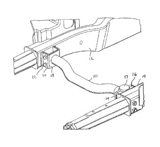
(12) Brevet: (11) CA 2528928
(54) Titre français: ELEMENT TRANSVERSAL INTEGRE AVEC ASSEMBLAGE DE BOITIER DE DIRECTION
(54) Titre anglais: INTEGRAL CROSS MEMBER WITH STEERING GEAR JOINT
Statut: Réputé périmé
Données bibliographiques
(51) Classification internationale des brevets (CIB):
  • B62D 7/00 (2006.01)
(72) Inventeurs :
  • KISELIS, GREGORY (Etats-Unis d'Amérique)
  • MATHAROO, DALIP K. (Etats-Unis d'Amérique)
  • GABBIANELLI, GIANFRANCO (Etats-Unis d'Amérique)
  • KOTAGIRI, SEETARAMA S. (Etats-Unis d'Amérique)
(73) Titulaires :
  • MAGNA INTERNATIONAL INC. (Canada)
(71) Demandeurs :
  • MAGNA INTERNATIONAL INC. (Canada)
(74) Agent: BRANDT, KERSTIN B.
(74) Co-agent:
(45) Délivré: 2014-08-05
(22) Date de dépôt: 2005-12-06
(41) Mise à la disponibilité du public: 2006-06-06
Requête d'examen: 2010-09-17
Licence disponible: S.O.
(25) Langue des documents déposés: Anglais

Traité de coopération en matière de brevets (PCT): Non

(30) Données de priorité de la demande:
Numéro de la demande Pays / territoire Date
60/632,938 Etats-Unis d'Amérique 2004-12-06

Abrégés

Abrégé français

Un châssis de véhicule à moteur comprend une paire d'éléments de châssis longitudinaux. Un élément transversal est présent pour maintenir les éléments du châssis dans une situation espacée. L'élément transversal possède une première extrémité configurée pour être montée à un premier des éléments longitudinaux de châssis et à une seconde extrémité pour une mise en prise à un boîtier de direction. La seconde extrémité enserre le boîtier de direction comme la seconde extrémité est fixée au second des éléments du châssis.


Abrégé anglais

A motor vehicle frame includes a pair of longitudinal frame members. A cross member is provided to maintain the frame members in a spaced apart condition. The cross member has a first end configured to mount to a first one of the longitudinal frame members and a second end configured to engage a steering gear housing. The second end sandwiches steering gear housing as the second end is fastened to a second one of the frame members.

Revendications

Note : Les revendications sont présentées dans la langue officielle dans laquelle elles ont été soumises.


Claims
What is claimed is:
1. A cross member for a motor vehicle frame having a pair of longitudinal
frame
members, said cross member comprising a first end configured to mount to a
first one
of said pair of longitudinal frame members and a second end configured to
engage a
steering gear housing, wherein said second end sandwiches said steering gear
housing
as said second end is fastened to a second one of said pair of longitudinal
frame
members, wherein said second end has a gear bracket attached thereto, said
gear
bracket having a configuration to complementarily fit with said steering gear
housing
2. A cross member according to claim 1, wherein said first end has a clevis
bracket
to nest onto a frame bracket mounted on said first one of said pair of
longitudinal frame
members.
3. A cross member according to claim 2, wherein said clevis bracket is
affixed to
the first end of the cross member.
4. A cross member according to claim 3, wherein said clevis bracket is
provided
with elongated apertures for receiving fasteners to join said clevis bracket
to said frame
bracket.
5. A cross member according to claim 1, wherein said gear bracket is cast
on the
second end.
6. A cross member according to claim 1, wherein said gear bracket is cast
and
affixed onto the second end.
7. A vehicle frame comprising a pair of longitudinal frame members and
cross
members interconnecting said frame members, wherein at least one cross member
has a
first end configured to mount to a first one of said pair of longitudinal
frame members
4

and a second end configured to engage a steering gear housing, wherein said
second
end sandwiches said steering gear housing as said second end is fastened to a
second
one of said pair of longitudinal frame members, wherein said second end of
said cross
member has a gear bracket attached thereto, said gear bracket having a
configuration to
complementarily fit with said steering gear housing
8. A vehicle frame according to claim 7, wherein said first end of said
cross
member has a clevis bracket to nest onto a frame bracket mounted on said first
one of
said pair of longitudinal frame members.
9. A vehicle frame according to claim 8, wherein said clevis bracket is
affixed to
the first end of the cross member.
10. A vehicle frame according to claim 9, wherein said clevis bracket is
provided
with elongated apertures for receiving fasteners to join said clevis bracket
to said frame
bracket.
11. A vehicle frame according to claim 7, wherein said gear bracket is cast
on the
second end.
12. A vehicle frame according to claim 7, wherein said gear bracket is cast
and
affixed onto the second end.
13. A vehicle frame comprising a pair of longitudinal frame members and
cross
members interconnecting said frame members, said cross members including a
first end
coupled to a first one of said pair of longitudinal frame members and a second
end
engaging a steering gear housing, wherein said steering gear housing is
sandwiched
between said second end of said cross members and a second one of said pair of

longitudinal frame members.

14. A vehicle frame according to claim 13, wherein said second end of said
cross
member has a gear bracket attached thereto, said gear bracket having a
configuration to
complementarily fit with said steering gear housing.
15. A vehicle frame according to claim 14, wherein said first end of said
cross
member has a clevis bracket to nest onto a frame bracket mounted on said first
one of
said pair of longitudinal frame members.
16. A vehicle frame according to claim 13, wherein said steering gear
housing
includes a first surface engaging said second one of said pair of longitudinal
frame
members.
17. A vehicle frame according to claim 16, wherein said steering gear
housing
includes a second surface opposite said first surface, said second surface
engaging a
flange formed at said second end of said cross member.
18. A vehicle frame according to claim 13, wherein said cross member
includes a
tubular shape.
6

Description

Note : Les descriptions sont présentées dans la langue officielle dans laquelle elles ont été soumises.

CA 02528928 2005-12-06
INTEGRAL CROSS MEMBER WITH STEERING GEAR JOINT
Field of the Invention
[0001] The present invention relates to a structural assembly for a
vehicle. In
particular, this invention relates to a cross member with an integral steering
gear joint.
Background Of The Invention
[0002] In body over frame type vehicles, the frame comprises longitudinal
members
that are interconnected with a series of cross members. The cross members are
welded to the
longitudinal members for structural rigidity. Vehicle components are then
mounted on the
frame.
[0003] In certain vehicles as illustrated in Fig. 1, the longitudinal
members 12, 14 are
interconnected with a forward cross member 100. The steering gear mount
portion16
(schematically illustrated) is mounted on the forward cross member 100,
immediately
adjacent the left hand side longitudinal member 14. However the position of
the steering gear
16 interferes with the mounting arrangement of the cross member 100 and sleeve
102 to the
longitudinal member 14. As a result, the cross member 100 cannot be fully
welded to the
longitudinal member 14. The recirculating ball steering gear is mounted with
single shear
joints, which joints cause noise, vibration, and harshness problems. Further,
dimensional
tolerances cannot be met leading to durability issues.
Summary Of The Invention
[0004] The disadvantages of the prior art may be overcome by providing a
structural
cross member for a vehicle frame that simultaneously mounts a steering gear
assembly and
mounts the cross member to the longitudinal member.
[0005] According to one aspect of the invention, there is provided a motor
vehicle
frame that includes a pair of longitudinal frame members with cross members
provided to
maintain the frame members in a spaced apart condition. At least one of the
cross members
has a first end configured to mount to a first one of the longitudinal frame
members and a
second end configured to engage a steering gear housing. The second end
sandwiches
steering gear housing as the second end is fastened to a second one of the
frame members.
1

CA 02528928 2005-12-06
[0006] Other aspects, features, and advantages of this invention will
become apparent
from the following detailed description when taken in conjunction with the
accompanying
drawings, which are a part of this disclosure and which illustrate, by way of
example, the
principles of this invention.
Brief Description Of The Drawings
[0007] The accompanying drawings facilitate an understanding of the
various
embodiments of this invention. In such drawings:
[0008] Fig. 1 is a partial perspective view of a frame of the prior art;
[0009] Fig. 2 is a partial perspective view of the frame with cross member
of the
present invention;
[0010] Fig. 3 is partial perspective view of the steering gear mount of
the embodiment
of Fig. 2
[0011] Fig. 4 is a partial perspective view of the steering gear mount,
from a reverse
angle from Fig 3;
[0012] Fig. 5 is a partial perspective view of the steering gear mount of
Fig 4; and
[0013] Fig. 6 is partial perspective view of the spacers for mounting the
cross member
of the present invention.
Description Of Illustrated Embodiments
[0014] Referring to Fig. 2, a frame incorporating the cross member
assembly of the
present invention is generally illustrated. The vehicle frame generally
comprises a pair of
spaced apart longitudinal members 12, 14 joined together by a cross member 10.
Other cross
members, as are common in the art, are also utilized but not illustrated to
provide a rigid
frame structure.
[0015] In the preferred embodiment, cross member 10 is tubular having an
inverted
saddle shape and made from steel tube, preferably 1008/1010 or any 35 ksi
steel or a grade of
high strength steel. The cross member 10 has clevis bracket 18 affixed to a
first end thereof.
Clevis bracket 18 is a U shaped bracket with the bight portion attached to the
cross member
10, preferably by welding. The bight portion has an aperture that
complementarily receives
the cross member 10. The side walls of the clevis bracket 10 each has a series
of oversized or
elongated slots or apertures 20. The clevis bracket 18 overlies a U shaped
frame bracket 22
that is welded onto the inside face of longitudinal bracket 12. The frame
bracket 22 nests
within the clevis bracket 18. The side walls of the frame bracket 22 each has
a series of
2

CA 02528928 2013-09-27
apertures that correspond with the apertures 20 of clevis bracket 18.
Fasteners, such as
rivets or nuts and bolts, securely join the frame bracket 22 to the clevis
bracket 18. The
oversized apertures 20 accommodate cross car variations for fit up.
[0016] Referring to Fig. 3, the opposite end of cross member 10 has a
gear
bracket 24. The gear bracket 24 is preferably nodular cast iron. The gear
bracket 24 is
attached to the end of cross member 10. Suitable joining methods include
welding and
cast in place as described in co-pending application no. 60/682,329, filed
April 19,
2005, which corresponds to issued U.S. Patent No. 7,806,162. The outer surface
of the
gear bracket 24 has a complementary fit with a housing 16 of a steering gear
assembly
17, schematically illustrated in the figures. Gear bracket 24 has a pair of
flanges having
apertures 25 therein. Apertures 25 are aligned with the apertures of the gear
assembly
housing, enabling an elongate fastener, such as a bolt or rivet to extend
therethrough.
[0017] To form a more stable and rigid connection, housing 16 is
sandwiched
between longitudinal frame member 14 and cross-member 10. The housing 16 nests
on
one side of the frame member 14 and is bolted onto the frame, providing a
double shear
joint for the mounting of the recirculating ball steering gear assembly 17.
The steering
gear housing thus becomes a structural member, while occupying less package
space
over the prior art.
[0018] Referring to Figures 5 and 6, a reverse view of the frame member
14 is
illustrated. The frame member 14 comprises two half sections 14a and 14b that
are
arranged in a face to face configuration to present a closed box section. To
support the
longitudinal frame member 14, a pair of spacers 26, 28 is provided to support
the frame
member 14 and prevent the frame member 14 from collapsing. Spacer 26 is
configured
to be inserted into the end of octagonal crush tip 30, which is frictionally
fitted within
the end of frame member 14. Thus, spacer 26 supports both the crush tip 30 and
the
frame member 14. Preferably, spacer 26 is omega shaped. Spacer 28 is
configured to
be frictionally fitted within the frame member 14. In the preferred
embodiment, the
spacer 28 is S shaped.
[0019] The description of the invention is merely exemplary in nature
and, thus,
numerous other embodiments may be envisaged without departing from the scope
of
the instant invention.
3

Dessin représentatif
Une figure unique qui représente un dessin illustrant l'invention.
États administratifs

Pour une meilleure compréhension de l'état de la demande ou brevet qui figure sur cette page, la rubrique Mise en garde , et les descriptions de Brevet , États administratifs , Taxes périodiques et Historique des paiements devraient être consultées.

États administratifs

Titre Date
Date de délivrance prévu 2014-08-05
(22) Dépôt 2005-12-06
(41) Mise à la disponibilité du public 2006-06-06
Requête d'examen 2010-09-17
(45) Délivré 2014-08-05
Réputé périmé 2021-12-06

Historique d'abandonnement

Il n'y a pas d'historique d'abandonnement

Historique des paiements

Type de taxes Anniversaire Échéance Montant payé Date payée
Le dépôt d'une demande de brevet 400,00 $ 2005-12-06
Enregistrement de documents 100,00 $ 2006-11-10
Taxe de maintien en état - Demande - nouvelle loi 2 2007-12-06 100,00 $ 2007-09-20
Taxe de maintien en état - Demande - nouvelle loi 3 2008-12-08 100,00 $ 2008-09-17
Taxe de maintien en état - Demande - nouvelle loi 4 2009-12-07 100,00 $ 2009-08-31
Taxe de maintien en état - Demande - nouvelle loi 5 2010-12-06 200,00 $ 2010-09-15
Requête d'examen 800,00 $ 2010-09-17
Taxe de maintien en état - Demande - nouvelle loi 6 2011-12-06 200,00 $ 2011-09-19
Taxe de maintien en état - Demande - nouvelle loi 7 2012-12-06 200,00 $ 2012-09-14
Taxe de maintien en état - Demande - nouvelle loi 8 2013-12-06 200,00 $ 2013-09-30
Taxe finale 300,00 $ 2014-05-22
Taxe de maintien en état - brevet - nouvelle loi 9 2014-12-08 200,00 $ 2014-11-13
Taxe de maintien en état - brevet - nouvelle loi 10 2015-12-07 250,00 $ 2015-11-11
Taxe de maintien en état - brevet - nouvelle loi 11 2016-12-06 250,00 $ 2016-11-17
Taxe de maintien en état - brevet - nouvelle loi 12 2017-12-06 250,00 $ 2017-11-15
Taxe de maintien en état - brevet - nouvelle loi 13 2018-12-06 250,00 $ 2018-11-14
Taxe de maintien en état - brevet - nouvelle loi 14 2019-12-06 250,00 $ 2019-11-14
Taxe de maintien en état - brevet - nouvelle loi 15 2020-12-07 450,00 $ 2020-11-11
Titulaires au dossier

Les titulaires actuels et antérieures au dossier sont affichés en ordre alphabétique.

Titulaires actuels au dossier
MAGNA INTERNATIONAL INC.
Titulaires antérieures au dossier
GABBIANELLI, GIANFRANCO
KISELIS, GREGORY
KOTAGIRI, SEETARAMA S.
MATHAROO, DALIP K.
Les propriétaires antérieurs qui ne figurent pas dans la liste des « Propriétaires au dossier » apparaîtront dans d'autres documents au dossier.
Documents

Pour visionner les fichiers sélectionnés, entrer le code reCAPTCHA :


Pour visualiser une image, cliquer sur un lien dans la colonne description du document. Pour télécharger l'image (les images), cliquer l'une ou plusieurs cases à cocher dans la première colonne et ensuite cliquer sur le bouton "Télécharger sélection en format PDF (archive Zip)" ou le bouton "Télécharger sélection (en un fichier PDF fusionné)".

Liste des documents de brevet publiés et non publiés sur la BDBC .

Si vous avez des difficultés à accéder au contenu, veuillez communiquer avec le Centre de services à la clientèle au 1-866-997-1936, ou envoyer un courriel au Centre de service à la clientèle de l'OPIC.


Description du
Document 
Date
(yyyy-mm-dd) 
Nombre de pages   Taille de l'image (Ko) 
Dessins représentatifs 2006-05-09 1 16
Abrégé 2005-12-06 1 11
Revendications 2005-12-06 3 148
Revendications 2005-12-06 2 62
Dessins 2005-12-06 5 107
Page couverture 2006-05-31 1 43
Description 2006-06-05 2 62
Description 2013-09-27 3 153
Revendications 2013-09-27 3 99
Dessins 2013-09-27 5 104
Dessins représentatifs 2014-07-09 1 12
Page couverture 2014-07-09 1 41
Poursuite-Amendment 2010-09-17 1 29
Correspondance 2006-01-19 1 26
Cession 2005-12-06 2 73
Cession 2006-11-10 4 132
Correspondance 2008-10-08 17 613
Correspondance 2008-11-13 1 18
Correspondance 2008-11-14 1 26
Poursuite-Amendment 2011-01-21 1 29
Correspondance 2012-01-11 1 18
Correspondance 2012-01-13 1 19
Correspondance 2011-12-13 19 698
Correspondance 2012-01-25 18 624
Correspondance 2012-02-09 1 17
Poursuite-Amendment 2013-09-27 10 302
Poursuite-Amendment 2013-03-27 2 71
Correspondance 2014-05-22 1 27