Note : Les descriptions sont présentées dans la langue officielle dans laquelle elles ont été soumises.
CA 02535072 2007-Ol-05
WO 2005/013826 PCT/CA2004/001467
Dual energy Imaging Using Optically Coupied Digital ~tadlography
System
Field of the Invention
The present invention Is directed generally to digital radiography, and
in particular to an optically-coupled digital radiography system that can
simultaneously acquire two images with different x-ray energy spectra for the
purpose of producing separable bone and salt tissue images.
Background of the Invention
For over a hundred years photographic films have been used to
capture and display x-rays for diagnostic purposes. In recent years, digital
radiography (DR) has become increasingly popular. DR refers to the
application of digital equipment and image processing techniques to
projection radiography. Digitally recorded x-rays are superior to those
recorded with photographic film due to the greater dynamic range offered by a
digital recording system. Furthermore, computer image processing
techniques provide a wealth of capabilities to study otherwise obscured
details within the image.
one type of DR Imaging device is an optically-coupled charge-coupl~d
device (CCD} DR system used for clinical diagnosis. Optically coupled CCD-
based DR systems use a scintillator screen, a mirror and a lens to capture
and reduce an x-ray image onto a CCD camera for digitization. To take a
digital radiograph using such a system, a DR imaging unit Is positioned
behind a subject. A standard radiographic generator positioned in front of the
subject directs radiation through the subject to a fluoresc~nt-imaging
scintillator screen mounted just behind the front surface of the imaging unit.
The scintillator screen is the conversion media for radiation to visible
light.
The scintillator screen absort~s the radiographic radiation and emits Ilght of
a
particular wavelength which closely matches the peak sensitivity of a CCD
t
CA 02535072 2007-Ol-05
WO 2005/013826 PCT/CA2004/001467
camera. A front-surfaced mirror is positioned at an angle inside the imaging
unit to direct fhe visible radiographic image into the CCD camera. The mirror
allows the CCD camera to be positioned cut of the direct path of the
radiation,
effectively shielding it from radiation exposure and prolonging its life. A
high-
efficiency fens is located between the mirror and camera and reduces the
image and directs it onto the surface of a CCD sensor in the camera.
The visual imag~ formed by the fluorescent-imaging screen Is
converted into a digital image by the CCD sensor. A control computer
converts the image into a medical image file that can be viewed for clinical
diagnosis, enhanced and electronically stpred with patient demographic
information in a picture archiving system.
Digital radiography has enabled the use of a technique known as dual
energy subtraction radiography, which exploits the energy dependence of x-
ray attenuation by different tissues. When producing multiple images of a
subject obtained by multiple x-ray exposures at different kilovolt peak (kVp)
levels andlor by a different filtering of a single x-ray exposure, the photons
will
interact differently In the scintillator ~nd I or subject. The proportion of
photoelectric absorption to Comptan scattering will be different in the
generation of the differ~nt images. Using this eff~ct, a third image can be
calculated from the two, in which for instance, the bone structure or soft
tissue
can be significantly enhanced or suppressed.
One known application of this technique uses a single x-ray exposure
detected by two phospor-based receptor plates separated by a filter, The
filter attenuates a portion of the x-ray spectrum, thereby enabling the
receptor
plates to produce two images of the same subject hut wi#~ different kVp
levels, and different contrast properties. Using these two images will make it
possible, for Instance, to separate the bone structures in one Image from the
other image, thereby gen~radng a third image that primarily shows soft tissue.
Digital imaging using phosphor-based r9eceptor plates is laborious and time
intensive as technologists typically must cony the plates to a reader and wait
a
CA 02535072 2007-Ol-05
WO 2005/013826 PCT/CA2004/001467
far the reader to energize the plates and record light flashes that correspond
to the energy imparted by the x-rays that struck the plates.
A different approach to dual energy digital imaging involves digital
imaging devices that use sequential x-ray exposures in rapid succession, at
different kVp settings. A scintillator produces multiple images when struck by
the multiple x-ray exposures, and these images are captured by a digital
sensor for image processing. because this technique involves multiple
sequential exposures, the time delay between exposures tends to cause
mieregistration resulting in a less-than-pertect separation of the bone and
soft
tissue components.
Therefore, it is desirable to provide a du21 energy DR technique that
enjoys the accuracy obtained by using a single exposure, and the processing
speed enjoyed by a scinGllator based Imaging system.
Summary of the Invention
According to one aspect of the invention, there is provided a DR
method and apparatus for simultaneously obtaining two distinct images of the
same subject, each of which represents a different x-ray energy spectrum.
The two images may be combined in various ways such that anatomical
features may be separated from one another to provide a ~ciearer view of
those features or of underlying structures.
In particular, there is provided an optically-coupled digital radiography
system far simultaneously producing multiple images of differing energies of a
subject from a single x-ray exposure of the subject. The system comprises
(a) a first scintillator that produces a visible first image when
subjected to an x-ray exposure of a subject;
(b) a first dig'~tal camera that is optically coupled to the first
scintillator, for capturing the first image;
3
CA 02535072 2007-Ol-05
WO 2005/013826 PCT/CA2004/001467
(c) an x-ray filter positioned in the path of the x-ray exposure and
downstream of the first scintillator, for selectively attenuating a
portion of the x-ray spectrum of the x-rays that have passed
through the first scintiliator;
(d) a second scintillatar positioned in the path of the x-ray exposure
and downstream of the filter and that produces a visible second
Image when subjected to x-rays that have passed through the
filter, the second image being different than the fret image; and
(e) a second digital camera optically coupled to the second
scintillator, for capturing the second imag~.
' When a camera is "optically coupled" to a scintillator, an optical
pathway is provided for a visible image produced by the scintillator to reach
the camera. For example, the first or second camera can be located out of
the path of the x-ray exposure and out of the line-of sight of the associated
scintillator. In such a case, a reflector is provided that is posit<oned in
line-of
sight of the associated sclntlllator and is angled to reflect the Image
produced
by the scintillator to the camera.
The first and second scintillators can have a fluorescing material
selected from a large group of known x-ray scintillating materials such as
terbium doped gadollineum oxysulflde and thallium doped cesium iodide. The
first and second sclntillators can each have different fluorescing materials
that
respond differently to the x-ray exposure, i.e. reacts to a different portion
of
the x-ray energy spectrum.
The x-ray filter can be a copper plate that is in adjacent parallel contact
with the reflector. The copper plat~ can alas serve as a support structure for
a reflector, and in such case Is coated on one major surtace with a reflective
layer and has sufficient thickness to attenuate the x-ray exposure and
mechanically support the reflective coating.
4
CA 02535072 2007-Ol-05
WO 2005/013826 PCT/CA2004/001467
The subject can comprise bane and~~'tissue and the system can further
comprise a computer communicative with the first and second camewas to
rec~iv~ the first and second images. The~;computer has a program that uses
the first and second images to produce a bbne-only or tissue-only third image,
then algebraically combines the third image.with the first or second images to
enhance certain features in the subj~ct. In particular, the computer comprises
intensity reference tables that associates one or more bone-tissue ratios with
a pixel intensity in a plurality of pixel intensities, and the program is
programmed to use the intensity reference tables to determine the actual
bone-tissue ratio in the subject, then to produce a bone-only or tissue oniy
third image from the actual bone-tissue ratio.
According to another aspect of the invenrion, there is provided an
optically-coupled digital radiography system comprising:
{a) a first scintillator comprising a first fluorescing material that
produces a visible first image when subjected to an x-ray
exposure,
(b) a first digital camera optically coupled to th~ first scintillator, for
capturing the first image;
(c) a second, scintillator positioned in the path of the x-ray exposure
and downstream of the first scintillator and comprising a second
fluorescing material that responds sufficiently differently to the x
ray exposure than the first scintillator material to produce a
visible second Image that is different from the first image; and
(d) a second digital camera optically coupled to the second
scintillator for capturing the second image.
In this aspect of the invention, there is no filter that attenuates the x-ray
beam before reaching the second scintillator. The differences in the first and
second images result from use of two different fluorescing scintillatar
materials, wherein each material intercepts and reacts to a different portion
of
the energy spectrum. Suitable scintiilator materials include CaWO~,
CA 02535072 2007-Ol-05
WO 2005/013826 PCT/CA2004/001467
BaPbSO~, BaFCI:Eu, LaOBr:Tm, Y202S:Tb, CsI:TI, GdaOZS:Tb, BaSrS04:Eu.
In order to choose a suitable pair of materials far the scintillators,
consideration is given to the portion of the x-ray spectrum to which the
materials are most sensitive. By choosing pairs of materials which are as
distinct as possible 1n their x ray characteristics, the greatest difference
will be
obtained between the two images. This in turn allows for the least ambiguous
separation of the density components by reference to reference tables which
chart the possible combinations of bone and soft issue which can give rise to
the observed pixel intensities within the ~ image. One such feasible
combination is CsI:TI and Gd2OaS:Tb.
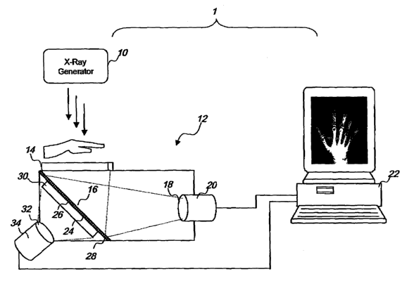
Brief Description of Drawings
Figure 1 is a schematic illustration of one embodim~nt of a dual energy
DR system having an x-ray filter interposed between two scintillators
constructed of the same scintillator material.
Figure 2 is a schematic illustration of.a second embodiment of a dual
energy DR system having a pair of scintillators constructed of different
scintillator materials.
DetaNed Description
Referring to Figure 1 and according to one embodiment of the
invention, an optically-coupled CCD-based DR system 1 is provided for
taking digital x-ray images of a subjaCt, such as a human patient, for
clinical
diagnostic purposes.
The system 1 is operable to simultaneously obtain two distinct images
of a subject, each of which represents a different x-ray energy spectrum. The
two images can be algebraically combined in various ways during image
processing, such that anatomical features can be separated from one another
to provide a clearer view of certain features of underlying structures. In
6
CA 02535072 2007-Ol-05
WO 2005/013826 PCT/CA2004/001467
particular, one image can be algebraically combined with another to produce
a third imag~ that enhances the bone structure or muscle tissue in the
subject.
In particular, the two different-energy images obtained by the system 1
can b~ processed to produce a third image Showing only bone or only soft
tissue. The process uses a set of intensity reference tables provided for each
scintillator response to the varying bone ! tissue ratios, to identify the
actual
ratio of bone-to-tissue of the subJect in the two images. Once so identified,
the system 1 can delete the bone to produce a tissue~nly third image, or
delete the tissue to produce a bone-only third image. This third image can
then be algebraically combined with the first or second image to enhance
certain details In those images; for example, a bone-only thlrci image can be
subtracted from the first image to suppress the bone detail and enhance the
soft tissue detail in the first image.
The system 1 has an x-ray Source 10 that sends x-rays through a
subject. When a patient is in position arid a part of the patient's body
selected for imaging has been set in place, the x-ray source 10 (s turned on
and x-rays are directed towards the patient. X-rays in a single exposure from
the x-ray source 10 pass through the patient and are captured by a detector
12 and converted into two digital x-ray images. In particular, some of the x-
rays reaching the detector 12 are first converted into visible light by a
first
seintillator 14 positioned orthogonal to the x-ray source 10. The visible
light
forms a visible image which is reflected by a mirror 18 towards lenses in a
first
fens assembly 18, which reduces and directs the image onto the surface of a
first CCD camera 20, which then converts the image into a fir3t digital image.
The first digital image is then transmitked to a computer' 22 for image
processing and storage.
In this embodiment, the mirror is positioned at a 41i d~gree angle to the
first scirttillator 14, and the first camera 20 is positioned in line of sight
of the
reflected image and out of the path of the x-ray exposure. Alternatively, the
7
CA 02535072 2007-Ol-05
WO 2005/013826 PCT/CA2004/001467
first camera 24 can be positioned at other locations inside the detector 12 so
long as it is out of path of the x-ray exposure, or if in the path of the x-
ray
exposure, is properly shielded When the camera is positioned in such an
alternative position, the mirror angle and lens assembly focal point are
adjusted accordingly.
The first scintillator 14 is made of a material which fluoresces wh~n
struck by x-rays, such as terbium doped gadollineum oxysulfide or thallium
doped cesium iodide. There are many other suitable scintillator materials,
such ~e CaW~d p~~a Rs~F~'I~~n ~~Rr~Tm Y~zS'Tb. BaSr$~4'Eu
and others as known in the art. All emit Ilght during this reaction when they
are struck by x-rays.
The mirror 16 comprises an x ray transparent support layer a4 coated
on one major surface with a thin reflective layer 26 and on its other surface
with a filter layer 28. In this embodiment, the support layer 24 composition
Is
plastic, the reflective layer 28 composition is aluminum, and the filter layer
28
composition Is copper. In particular, the copper fitter layer 28 has a
thickness
of about 0.5 mm; however, any suitable metal filter layer as known in the art
may be substituted. Alternatively, the mirror 16 comprises a metal layer that
serves as both a support layer and filter layer, and a reflective layer
coating
one side of the metal layer.
X-rays that are not attenuated by the first scintilla~r 14 reach the mirror
18. Most of these x-rays pass through th~ support and reflective layers 24,
2g, as these materials have low attenuation characteristics, and reach the
copper filter layer 28. The filter layer 28 absorbs most of the lower energy x-
rays, such that the x-rays that pass through the filter layer are
predominantly
high-energy x-rays, in other words, the >~Iter layer 28 serves to "harden" the
x-
ray beam.
The predominant!)r high energy x-rays in the hardened beam then
continue through the filter layer 28 and reach a second scintlllatar 30
mounted
8
CA 02535072 2007-Ol-05
WO 2005/013826 PCT/CA2004/001467
to the filter side of the mirror 18. In this embodiment, the second
scintillator
30 is made of the same material as the first scintillator 14. The x-rays
activate
the second scintillator 30, causing It to emit a second visible imag~. As .
compared to the first scintillator 14, the second sclntillator is exposed to
more
of the predominantly high energy x-rays, and therefore, the visible image
produced by the second scintlllator 30 ("high energy image°) has
different
contrast properties compared to the visible image produced by the first
scintillator 14 ("low energy image').
This high energy Image is then reduced by a second lens assembly 32;
the reduced image Is then directed onto the surface of a second GCD camera
34, which converts the visual image into a second digital image. The second
digital image Is then transmitted to the computer 22 for imaging processing
and storage. The second CCD camera 34 is mounted facing the second
scintillator 30 and out of the path of the x-ray source 10. Alternatively, the
second camera 34 can be positioned at other locations inside the detector 12
so long as it is out of path of the x-ray exposure, or if in the path of the x-
ray
exposure, Is properly shielded. When the camera is positioned in such an
alternative position, a second mirror can b~ provided and the second lens
assembly focal point can be adjusted accordingly.
In this embodiment, th~ filter layer 28 Is in adjacent parallel contact with
the support layer 24 and the second scintillator 30 is in adjacent parallel
contact with the filter layer 28; however, the filter layer 28 and second
scint111ator 30 can be positioned differently, so long as they are in the path
of
the x-ray exposure, e.g. the fitter layer 28 and second scinGllator 30 can be
placed parallel to the first scintillator 14 and orthogonal to the x-ray
source 10
(not shown). In this alternatlve~ configuration, a second mirror (not shown)
is
provided to reflect the visible image produced by the'second scintillator 30
to
the second CCD camera 34.
The x-ray source 10, sciodllators 14. 30. lens assemblies 18, 32 and
CCD cameras 20, 34 are per se known in the art, and for example, can be
9
CA 02535072 2007-O1-05
WO 2005/013826 PCT/CA2004/001467
those manufactured by Imaging Dynamics Company Ltd for their Xplorer 1700
detector.
Once th~ high and low energy images have been acquired, the
computer 22 can then run a program that eliminates the bone or soft tissue
components from an image altogether, by using s set of intensity reference
tables provided for each scintillatar response to the varying bone I tissue
ratios to identify the actual ratio of bone-to-tissue of the subject in the
two
images. The reference tables comprise a set of boneltissue ratios associated
with a set of pixel intensities, and are stored in memory on a computer 22 for
use during Image processing. The reference tables are constructed from
exposures of multiple test subjects. The different test subjects represent
different ratios of bone to tissue, and comprise different ratios of a first
material such as aluminum to represent bone density, and a second material
such as Lucite to represent soft tissue density. The exposures of these test
subjects activate a scintillator, which in tum emits visible light for capture
by a
CCD camera. The Intensity of each pixel in each exposure is recorded and
associated with the exposed test subject, and thus to the bone-to-tissue ratio
associated with that test subject.
To determine the actual bone/tlssue ratio of the imaged subject, the
computer 22, for each image A, correlates the measured intensity IA of each
pixel P,4p,p at positions (i,~ In the Image A to one or more bone-tissue
ratios in
the reference map. As there can be multiple bone-tissue ratios for each pixel
intensity, the computer 22 compares the associated bone-tissue ratios for the
pixel P~p,p in the first image to the bone-tissue ratios for the pixel P2p,~
in the
second image. As images 1 and 2 represent the same subject, the
boneltissue ratio common to both images 1,2, will be selected as the actual
bone-tissue ratio of the imaged subject. Knowing this ratio, a new image
showing only bone or only soft tissue can be constructed. This new image
can then be algebraically combined with the first or second image to ~nhance
certain details in those images; for example, a bone-only image can be
g0
CA 02535072 2007-O1-05
WO 2005/013826 PCT/CA2004/001467
subtracted from the first image to suppress the bone detail and enhance the
soft tissue detail in the first image.
For example, if a pixel P, at position i,j in the first image has intensity
I,, it may be seen from look up table R, of reference values far a first
scintillator to represent either x~ millimeters of bone and y~ millimeters of
soft
tissue or xa millimeters of bone and ya millimeters of soft tissue. Pixel P2
at
position I,j in the second Imag~ has ~a different intensity Iz which from the
reference table RZ for a second scintillator may represent either xa
millimeters
of bone and yZ millimeters of soft tissue or x~ millimeters of bone and y3
millimeters of soft tissue. Given that both pixels P~ and P2 represent the
same anatomy, they must represent the same ratio of bone to soft tissue.
The correct ratio Is therefore the one candidate common to both tables, xz and
y2. Over methods can also be used but all are dependent on having two
Images of the same subject imaged with different responses to the incident
beam. h should be noted that the different response may be due to either a
difference in the beam or a diff~rence In the receptor.
According to a second embodiment of the Invention and referring to
Figure 2, the system 1 om(ts the filter layer 28 used in the fret embodiment
and instead uses different scintillator materials for the two scintillators
14, 30
to produce different visible imag~s. In particular, the first scintillator 14
is
composed of thallium doped cesium Iodide while the second scintillator 30 is
composed of ' terbium doped gadolineum oxysulfide. The two materials
respond differently to the incident x-ray beam and thereby provide the two
distinct data sets required for th~ dual energy separation. The reference
tables in the computer are modified to include a set of intensity reference
tabl~s for the second scintillator's 30 response to the varying bone I tissue
ratios. There are many suitable scint111ator materials, such 2~s CaW04,
BaPbS04, BaFCI:Eu, l-aOBr:Tm, YzOzS:Tb, CsI:TI, GdZ4as:Tb, BaSrSOa:Eu
and others as known In the ~rt in which pairs of materials may be chosen for
the two scintillators 14, 30. In onier to choose g suitable pair of materials
for
the scintillators 14, 30, consideration is given to the portion of the x-ray
11
CA 02535072 2007-O1-05
WO 2005/013826 PCT/CA2004/001467
spectrum to which the materials are most sensitive. By choosing pairs of
materials which are as distinct as possible in their x-ray characteristics,
the
greatest difference will be obtained between the two images. This in tum
allows for the least ambiguous separation of the density componenia by
reference to look up tables which chart the possible combinations of bone and
soft tissue which can give rise to the observ~d pixel intensities within the
image. The principal factor in determining the difference in absorption of the
materials is the atomic number. The photoelectric absorption edge of the
material becomes more pronounced as the atomic number of the absorber
increases.
According to a third embodiment of the Invention, the system 1
comprises both the beam hardening filter layer 28 of the first embodiment and
the different scintillators 14, 30 of the second embodiment to produce two
different visible images.
While the preferred embodiment of the invention has been illustrated
and described, it will be appreciated that various changes can be made
therein without departing from the scope and spirit of the invention.
12