Note : Les descriptions sont présentées dans la langue officielle dans laquelle elles ont été soumises.
CA 02538359 2006-03-09
WO 2005/025785 PCT/US2004/029229
TITLE: Layered Manufactured Articles Having Small-Diameter Fluid Conduction
Vents and Methods of Malcin~ Same
Technical Field
The present invention relates to layered manufactured articles which contain
at
least one small-diameter fluid conduction vent. More specifically, the present
invention relates to such articles wherein at least one such vent is produced
during the
layered manufacturing process. The present invention also relates to methods
for
making such articles.
Background Art
Many articles of manufacture contain small-diameter fluid conduction vents
which permit fluid to flow into and/or out of the article or a portion of the
article. For
example, molds for making articles from expanded polymer beads like expanded
polystyrene ("EPS") contain a plurality of small-diameter fluid conduction
vents for
conducting steam into the mold for causing the polymer beads to further expand
and
bond together. Injection molding molds contain small-diameter fluid conduction
vents that allow trapped air to escape from the mold during the injection
process.
Vacuum forming tools, such as those used for thermoforming plastic sheets,
contain
small-diameter fluid conduction vents for drawing a vacuum between the tool
and the
plastic sheet that is to be formed against the tool surface. Fluid regulating
devices,
such as those used in shock absorbers, also contain at least one small-
diameter fluid
conduction vent. Heat exchange devices that use either open-loop and closed
loop
heat exchangers also may contain small-diameter fluid conduction vents.
At present, the creation of a small-diameter fluid conduction vent or vents
requires some type of perforation step to be performed on the article, e.g.,
punching or
drilling by some mechanical, electrical, optical or chemical means. In the
case of EPS
bead molds, vent making requires shouldered holes of between about 0.16 cm and
about 0.64 cm to be drilled, cylindrical hardware having slotted end surfaces
to be
press fitted into the holes, and the mold surface to be machined to assure
that the
hardware is flush with the mold surface. Alternatively, such vents may be made
by
laser-drilling followed by manual cleanup of the mold surface to remove flash
and
other irregularities caused by the laser-drilling operation. Such vents may
also be
created by electrodischarge machining or by chemical etching or drilling.
I
CA 02538359 2006-03-09
WO 2005/025785 PCT/US2004/029229
Such vent-making processes are costly and time consuming. Moreover, they
restrict the placement of vents to areas that are accessible to the tool that
will be used
for making the vent. If a vent is required in an otherwise inaccessible area,
it is
necessary to section the article so that the desired area can be accessed,
make the vent
or vents in the removed section, and then reintegrate the removed area back
into the
article.
Another drawback of the prior art is that the orientation of the small-
diameter
fluid conduction vents with respect to the article surface is restricted by
the
perforation technique employed and the accessibility of the portion of the
surface at
which an individual small-diameter fluid conduction vent is to be placed.
Where the
surface shape curves or is complex or access is limited, the small-diameter
fluid
conduction vent is likely to have a less-than-optimal orientation. Where
techniques
such as laser or chemical drilling are used, the orientation of the small-
diameter fluid
conduction vent is usually confined to being nearly perpendicular to the
article
surface.
What is needed is a method of producing articles that contain at least one
small-diameter fluid conduction vent that avoids the costs and the
difficulties
associated with the use of a perforation technique to produce the vent or
vents.
Disclosure of Invention
One aspect of the present invention is to provide a method of producing
articles that contain at least one small-diameter fluid conduction vent which
avoids
one or more of the drawbacks inherent in the prior art. To this end, the
present
invention utilizes a layered manufacturing process to produce an article
having at least
one small-diameter fluid conduction vent wherein the vent or vents are
produced
during the layered manufacturing process.
The term "layered manufacturing process" as used herein and in the appended
claims refers to any process which results in a useful, three-dimensional
article that
includes a step of sequentially forming the shape of the article one layer at
a time.
Layered manufacturing processes are also known in the art as "rapid
prototyping
processes" when the layer-by-layer building process is used to produce a small
number of a particular article. The layered manufacturing process may include
one or
more post-shape forming operations that enhance the physical and/or mechanical
properties of the article. Preferred layered manufacturing processes include
the three-
2
CA 02538359 2006-03-09
WO 2005/025785 PCT/US2004/029229
dimensional printing ("3DP") process and the Selective Laser Sintering ("SLS")
process. An example of the 3DP process may be found in United States. Pat. No.
6,036,777 to Sachs, issued March 14, 2000. An example of the SLS process may
be
found in United States Pat. No. 5,076,869 to Bourell et al., issued Dec. 31,
1991.
Layered manufacturing processes in accordance with the present invention can
be
used to produce articles comprised of metal, polymeric, ceramic, or composite
materials.
The term "small-diameter" as used herein and the appended claims refers to
diameters of about 0.25 cm or less. Preferably, with regard to the present
invention,
the small-diameter fluid conduction vents have diameters in the size range of
from
about 0.02 cm to about 0.25 cm.
In contradistinction to the prior art, the present invention gives the article
designer the freedom to locate the small-diameter fluid conduction vent or-
vents
wherever they are most needed without resort to sectioning and reassembling
the
article. The present invention also permits the article designer to optimize
both the
orientation of the vent or vents and the placement density of multiple vents.
For
example, the present invention allows the designer to orient the vents of an
EPS bead
mold parallel to the mold's opening direction to facilitate the easy removal
of the
formed EPS part and reduce the likelihood of vent blockage by EPS material
that
might extrude into a vent. The present invention also permits the designer to
use a
high placement density of vents in areas needing a large amount of ventilation
while
using a lower placement density of vents in areas needing less ventilation.
Moreover,
the flexibility provided by the present invention permits the designer to use
a
computer-run algorithm to optimize vent design, placement, and array density.
The
computer program containing the algorithm may even create an electronic file
incorporating the vents into the article and cause the article to be printed,
all with little
or no human intervention after the design criteria have been selected.
Another aspect of the present invention is to provide articles containing at
least one small-diameter fluid conduction vent wherein the article and the
small-
diameter vent or vents are simultaneously produced by a layered manufacturing
process.
Articles produced by the present invention are particularly well-suited for
producing EPS molded foamed articles for use as patterns in lost-foam molding
3
CA 02538359 2006-03-09
WO 2005/025785 PCT/US2004/029229
process, drinking cups, Christmas decorations, packing material, floatation
devices,
and insulation material.
Brief Description of Drawing
The criticality of the features and merits of the present invention will be
better
understood by reference to the attached drawings. It is to be understood,
however,
that the drawings are designed for the purpose of illustration only and not as
a
definition of the limits of the present invention.
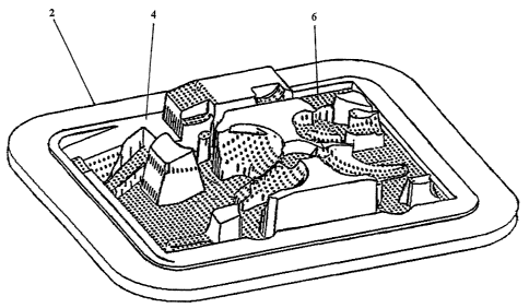
FIG. 1 is a perspective view of one half of an EPS bead mold containing vents
that was produced according to the present invention.
Modes for Carrying Out the Invention
In this section, some presently preferred embodiments of the present invention
are described in detail sufficient for one skilled in the art to practice the
present
invention. It is to be understood, however, that the fact that a limited
number of
presently preferred embodiments are described herein does not in any way limit
the
scope of the invention as set forth in the appended claims.
For clarity of illustration and conciseness, the description of presently
preferred embodiments is limited to the description of making EPS bead molds
wherein the layered manufacturing process employed is the 3DP process. Persons
skilled in the art will recognize that the present invention includes the
making of any
type of article having one or more small-diameter fluid conduction vents which
is
within the size and material capability of any layered manufacturing process
that is
adaptable to the inclusion of one or more small-diameter fluid conduction
vents in the
article as it is being built in a layer-wise fashion.
In a conventional EPS bead molding operation, partially-expanded EPS beads
are charged into a closed two-piece EPS bead mold. Steam is then introduced
into a
chamber surrounding the EPS bead mold. The steam is conducted through a
plurality
of small-diameter fluid conduction vents in the EPS bead mold and causes the
blowing agent, such as pentane, within the partially-expanded EPS beads to
further
expand the beads, which then become fused together in the shape defined by the
EPS
bead mold. After the steaming step is completed, the molded article is cooled
by
applying a vacuum to the chamber surrounding the EPS bead mold and/or by
spraying
4
CA 02538359 2006-03-09
WO 2005/025785 PCT/US2004/029229
water on the outer surfaces of the EPS bead mold. The EPS bead mold is then
opened
and the molded part is removed. A conventional EPS bead molding operation is
described in United States Pat. No. 5,454,703 to Bishop, issued October 3,
1995.
The diameter of the vents that conduct the steam into the EPS bead mold must
be smaller than the partially-expanded EPS bead size to prevent the beads from
either
clogging the vents or exiting the mold cavity through the vents. Typically,
the
partially-expanded EPS beads are on the order of about 0.05 cm in diameter.
Partly
because of this small size, and partly because of the need to contact with
steam all of
the partially-expanded EPS beads that are charged into the cavity of the EPS
bead
mold, it is desirable to have small-diameter fluid conduction vents located
over as
much of the EPS bead mold surface as possible. However, the problems of
perforation tool accessibility to complex or recessed areas of the EPS bead
mold's
molding surface makes it difficult to optimize vent placement by conventional
EPS
bead mold making techniques.
In accordance with an aspect of the present invention, a plurality of small-
diameter fluid conduction vents may be incorporated into each part of the EPS
bead
mold as the EPS bead mold part is manufactured by a layered manufacturing
process,
e.g., the 3DP process.
The 3DP'process is conceptually similar to inlc jet printing. However, instead
of ink, the 3DP process deposits a binder onto the top layer of a bed of
powder. This
binder is printed onto the powder layer according to a two-dimensional slice
of a
three-dimensional electronic representation of the article that is to be
manufactured.
One layer after another is printed until the entire auicle has been formed.
The powder
may comprise a metal, ceramic, polymer, or composite material. The binder may
comprise at least one of a polymer and a carbohydrate. Examples of suitable
binders
are given in United States Pat. No. 5,076,869 to Bourell et al., issued Dec.
31, 1991,
and in United States Pat. No. 6,585,930 to Liu et al, issued July l, 2003.
The printed article typically consists of from about 30 to over 60 volume
percent powder, depending on powder packing density, and about 10 volume
percent
binder, with the remainder being void space. The printed article at this stage
is
somewhat fragile. Post-printing processing may be conducted to enhance the
physical
and/or mechanical properties of the printed article. Typically, such post-
printing
processing includes thermally processing the printed article to replace the
binder with
an infiltrant material that subsequently hardens or solidifies, thereby
producing a
5
CA 02538359 2006-03-09
WO 2005/025785 PCT/US2004/029229
highly dense article having the desired physical and mechanical properties.
Where an
infiltration step is used, it is necessary to prevent the infiltration from
closing off the
small-diameter fluid conduction vents. The techniques described in United
States Pat.
No. 5,775,402 to Sachs et al., issued July 7, 1998, with regard to avoiding
infiltrant
from blocking coolant channels formed within layered manufactured articles may
be
employed to prevent infiltrant from blocking vents in articles produced
according to
the present invention.
The three-dimensional electronic representation of the article that is used in
the layered manufacturing process is typically created using Computer-Aided
Design
("CAD") software. The CAD file of the three-dimensional electronic
representation
is typically converted into another file format known in the industry as
stereolithographic or standard triangle language ("STL") file format or STL
format.
The STL format file is then processed by a suitable slicing program to produce
an
electronic file that converts the three-dimensional electronic representation
of the
article into an STL format file comprising the article represented as two-
dimensional
slices. The thickness of the slices is typically in the range of about 0.008
cm to about
0.03 cm, but may be substantially different from this range depending on the
design
criterion for the article that is being made and the particular layered
manufacturing
process being employed. Suitable programs for making these various electronic
files
are well-known to persons skilled in the art.
The making of one piece of a two-piece EPS bead mold will now be described
as an illustration of practicing an aspect of the present invention. Each
piece of the
EPS bead mold is considered herein to be a separate article, and the second
piece may
be made either separately from or simultaneously with the first piece.
First, a three-dimensional electronic representation of the mold piece is
created as a CAD file and then converted into an STL format file. Next, a CAD
file is
created of a three-dimensional electronic representation of the array of small-
diameter
fluid conduction vents that the article is to have. The CAD file of the array
of vents is
then converted into an STL format file.
Persons skilled in the art will recognize that in creating each of the article
and
vent CAD files, the dimensions of the article and the vents must be adjusted
to take
into consideration any dimensional changes, such as shrinlcage, that may take
place
during the manufacturing process. For example, in order to compensate for
shrinkage
6
CA 02538359 2006-03-09
WO 2005/025785 PCT/US2004/029229
during the manufacture by a 3DP process of a particular article, a vent that
is to have a
final diameter of 0.046 cm may be designed to be printed with a 0.071 cm
diameter.
The two STL format files are compared to make sure that the individual vents
will be in desired positions in the article. Any desired corrections or
modifications to
the STL files may be made thereto. The two STL format files are then combined
using a suitable software program that performs a Boolean operation such as
binary
subtraction operation to subtract the three-dimensional representation of the
vents
from the three-dimensional representation of the article. An example of such a
program is the Magics RP software, available from Materialise NV, Leuven,
Belgium.
Desired corrections or modifications may also be made to the resulting
electronic
representation, e.g., removing vents from areas where they are not wanted.
The file combination step results in a three-dimensional electronic file of
the
article which contains the desired array of small-diameter fluid conduction
vents.
Such an electronic file is referred to herein as a "3-D vented-article file."
A
conventional slicing program then may be used to convert the 3-D vented
article file
into an electronic file comprising the article represented as two-dimensional
slices.
Such an electronic file is referred to herein as a "vented article 2-D slice
file." The
vented article 2-D slice file may be checked for errors and any desired
corrections or
modifications may be made thereto. The vented article 2-D slice file is then
employed by a 3DP process apparatus to create a printed version of the
article, which
may subsequently be processed further to improve its physical andfor
mechanical
properties. An example of such a 3DP process apparatus is a ProMetal°
Model RTS
300 unit that is available from Extrude Hone Corporation, Irwin, PA 15642.
It is to be understood that the method disclosed in the preceding paragraphs
for producing an electronic representation of the article containing the
desired small-
diameter fluid conduction vent or vents that is usable by a layered
manufacturing
process apparatus to make the auticle layer-by-layer is only one of many ways
to make
such an electronic representation. The exact method used is up to the
discretion of the
designer and will depend on factors such as the complexity and size of the
article, the
size and number of the small-diameter fluid conduction vents that the article
is to
have, the computer processing facilities that are available, and the amount of
computational time that is available for processing the electronic file or
files. For
example, where a simple article contains only a single small-diameter fluid
conduction vent, it may be expeditious to include the vent into the initial
CAD file
7
CA 02538359 2006-03-09
WO 2005/025785 PCT/US2004/029229
containing the three-dimensional electronic representation of the article. In
other
cases, it may be desirable to eliminate just the step of comparing the STL
files of the
vent array and the article prior to combining the two files. Persons skilled
in the art
will recognize that some layered manufacturing processes make the slicing step
transparent to the user, i.e., the user only inputs into the processing
apparatus a CAD
or STL file of a three-dimensional representation of the object and the
apparatus
automatically performs the additional operations necessary to generate the two-
dimensional slices needed to construct the article layer-by-layer.
Nonetheless, the
slicing operation still is performed in such processes. It is to be understood
that all
possible variations of producing an electronic representation of the article
having a
small-diameter fluid conduction vent or vents that are utilizable by a layered
manufacturing process apparatus are within the contemplation of the present
invention.
The present invention permits the designer to use a computer-run algorithm to
optimize vent design, placement and array density. The computer program
containing
the algorithm may be used to also create an electronic file incorporating the
vents into
the article, e.g., in the manner described above. It may also cause the
article to be
printed. Thus, this aspect of the present invention permits the designer to go
from
design criterion to printed article all with little or no human intervention
after the
design criteria have been selected. The design of such an algorithm and the
related
software to run it is well within the skill of those skilled in the art
through the
integration of the principles of fluid dynamics, article design, machine
automation,
and computer programming.
Another aspect of the present invention is to provide articles containing at
least one small-diameter fluid conduction vent wherein the article and the
vent or
vents are simultaneously produced by a layered manufacturing process. Examples
of
such articles include, without limitation, EPS bead molds and portions
thereof, vented
injection molds, vacuum forming tools, heat transfer devices, and fluid
regulating
devices, such as those used in shoclc absorbers.
Persons skilled in the art will recognize that articles that are within the
contemplation of the present invention are distinguishable from articles
having small-
diameter fluid conduction vents made by other methods. For example, in some
cases,
such articles may be distinguished by the placement and orientation of the
vent or
vents which are not achievable by any other production means. This is so
because the
8
CA 02538359 2006-03-09
WO 2005/025785 PCT/US2004/029229
prior art placement and orientation of vents is restricted by perforation tool
accessibility, whereas the present invention permits vents to be placed
anywhere in
the article and oriented in any direction. Articles made according to the
present
invention may also be distinguished by the wall texture of the individual
vents as the
walls of vents produced by perforation means may exhibit signs of the vent-
forming
method employed whereas vents made according to the present invention may
exhibit
a texture characteristic of the layer-by-layer building process that was used
to produce
the article.
An example of an article containing small-diameter fluid conduction vents
wherein the article and the vents were simultaneously produced by a layered
manufacturing process is shown in FIG. 1. The article shown is the lower half
of an
EPS bead mold that is used for making a lost foam pattern for a demonstration
single-
cylinder engine head. The mold half 2 has a complex mold surface 4 and, at the
print
stage, is 28.2 cm long by 23.1 cm wide by 5.8 cm thick. The mold half 2
contains
several hundred small-diameter fluid conduction vents 6. Each of the vents 6
is
cylindrical with a round cross-section and is 0.09 cm wide. The vents 6 are
all
oriented parallel to the opening direction ~ of the EPS bead mold, i.e. the Z-
direction.
The complex curvature of the mold surface 4 causes some of the vents 4 to
appear
elongated at their terminations in the mold surface 4. The printed mold half 2
was
made using the 3DP process using grade 420 stainless steel powder that had a
particle
size of -170 mesh/ + 325 mesh and a printing binder. The printing binder was
ProMetal'~ SBC-1, a carbohydrate/acrylic binder that is available from Extrude
Hone
Corporation, Irwin, PA 15642.
The printed article was subsequently infiltrated with a 90 percent by weight
copper, 10 percent by weight tin bronze alloy to enhance its physical and
mechanical
properties. During the infiltration step, infiltrant flow into the vents was
substantially
prevented by controlling the elevation of the printed article above the source
from
which the infiltrant was wicked into the printed article so as to balance the
capillary
forces of infiltration with the static head pressure of the infiltrant. This
elevation
control technique permitted the article to be fully infiltrated without
obstructing the
vents 6 with infiltrant or causing them to become undersized. Another
technique that
can be used instead of or in addition to the elevation control technique to
prevent the
vents from being obstructed or becoming undersized by the infiltrant is to
oversize the
9
CA 02538359 2006-03-09
WO 2005/025785 PCT/US2004/029229
vents 6 to allow for some skinning of the interior surfaces of the vents 6 by
the
infiltrant.
Only a relatively small amount of surface finishing work was necessary to
produce the desired surface finish to the mold surface 4.
While only a few embodiments of the present invention have been shown and
described, it will be obvious to those skilled in the art that many changes
and
modifications may be made thereunto without departing from the spirit and
scope of
the invention as described in the following claims. All United States patents
referred
to herein are incorporated herein by reference as if set forth in full herein.