Sélection de la langue

Search

Sommaire du brevet 2540499 

Énoncé de désistement de responsabilité concernant l'information provenant de tiers

Une partie des informations de ce site Web a été fournie par des sources externes. Le gouvernement du Canada n'assume aucune responsabilité concernant la précision, l'actualité ou la fiabilité des informations fournies par les sources externes. Les utilisateurs qui désirent employer cette information devraient consulter directement la source des informations. Le contenu fourni par les sources externes n'est pas assujetti aux exigences sur les langues officielles, la protection des renseignements personnels et l'accessibilité.

Disponibilité de l'Abrégé et des Revendications

L'apparition de différences dans le texte et l'image des Revendications et de l'Abrégé dépend du moment auquel le document est publié. Les textes des Revendications et de l'Abrégé sont affichés :

  • lorsque la demande peut être examinée par le public;
  • lorsque le brevet est émis (délivrance).
(12) Demande de brevet: (11) CA 2540499
(54) Titre français: CLAPET ANTI-RETOUR DOUBLE
(54) Titre anglais: DUAL CHECK VALVE
Statut: Morte
Données bibliographiques
(51) Classification internationale des brevets (CIB):
  • F16K 15/00 (2006.01)
  • E21B 34/06 (2006.01)
  • F16K 15/03 (2006.01)
  • F16K 15/06 (2006.01)
(72) Inventeurs :
  • LEEB, GERALD (Canada)
(73) Titulaires :
  • LEEB, GERALD (Canada)
(71) Demandeurs :
  • LEEB, GERALD (Canada)
(74) Agent: LAMBERT INTELLECTUAL PROPERTY LAW
(74) Co-agent:
(45) Délivré:
(22) Date de dépôt: 2006-03-17
(41) Mise à la disponibilité du public: 2007-09-17
Licence disponible: S.O.
(25) Langue des documents déposés: Anglais

Traité de coopération en matière de brevets (PCT): Non

(30) Données de priorité de la demande: S.O.

Abrégés

Abrégé anglais


A check valve comprising a section of a drill string, a flapper valve
positioned
within and concentric to the section of the drill string, and a piston valve
positioned within
and concentric to the section of the drill string. The flapper valve allows
fluid flow in a first
direction through an inner portion of a cross-section of the section of the
drill string and not
allowing fluid flow in a second direction, and the piston check valve allowing
fluid flow in
the first direction through an outer portion of the cross-section of the
section of the drill
string and not allowing fluid flow in the second direction, where the first
portion and the
second portion of the cross-section of the section of the drill string are
mutually exclusive.

Revendications

Note : Les revendications sont présentées dans la langue officielle dans laquelle elles ont été soumises.


6


I claim:


1. A check valve comprising:
a housing;
a first check valve positioned within and concentric to the housing, the first
check
valve allowing fluid flow in a first direction through an inner portion of a
cross-section of
the housing and not allowing fluid flow in a second direction; and
a second check valve positioned within and concentric to the housing, the
second
check valve allowing fluid flow in the first direction through an outer
portion of the cross-
section of the housing and not allowing fluid flow in the second direction,
where the first
portion and the second portion of the cross-section of the housing are
mutually exclusive.

2. The check valve of claim 1, wherein each of the first check valve and the
second
check valve are selected from a group consisting of a flapper valve, a piston
valve, a ball
valve and a poppet valve.

3. The check valve of claim 1, wherein the first check valve is a flapper
valve and the
second check valve is a piston valve.

4. The check valve of claim 1, wherein the first valve opens to allow fluid
flow in the
first direction when fluid pressure above a first threshold is applied, and
the second valve
opens to allow fluid flow in the first direction when a fluid pressure above a
second
threshold that is higher than the first threshold is applied.

5. The check valve of claim 3, wherein the piston valve is biased closed by
either a
spring or fluid pressure within the piston chamber.

6. The check valve of claim 5, wherein the housing comprises a port to apply
fluid
pressure to the piston chamber.

7. The check valve of claim 1, wherein the housing comprises a section of a
drill string.


7


8. The check valve of claim 1, wherein surfaces that redirect abrasive flows
within the
first and second check valves are tapered surfaces.

9. The check valve of claim 1, wherein the second check valve is positioned
within an
inner wall of the housing, the second check valve having an annular shape, and
the first
check valve is positioned within the annular shape wall of the second check
valve.

10. A check valve comprising:
a section of a drill string;
a flapper valve positioned within and concentric to the section of the drill
string, the
flapper valve allowing fluid flow in a first direction through an inner
portion of a cross-
section of the section of the drill string and not allowing fluid flow in a
second direction; and
a piston valve positioned within and concentric to the section of the drill
string, the
piston valve allowing fluid flow in the first direction through an outer
portion of the cross-
section of the section of the drill string and not allowing fluid flow in the
second direction,
where the first portion and the second portion of the cross-section of the
section of the drill
string are mutually exclusive.

Description

Note : Les descriptions sont présentées dans la langue officielle dans laquelle elles ont été soumises.


CA 02540499 2006-03-17

DUAL CHECK VALVE
BACKGROUND OF THE INVENTION
[0001] A check valve is designed to open under certain pressure conditions,
and close
under others. Check valves are often used in tubing strings for applications
such as drilling,
fishing, and completing bottom hole assemblies to prevent hydrocarbons or
unwanted fluids
from flowing back up the tubing string. Examples of these types of valves are
models "FC",
"F", "GC" and "G" drill pipe float valves produced by Bakerline of San
Antonio, Texas. A
disadvantage with these check valves is that they limit flow through them for
a given
pressure. Under some circumstances, this could result in a downhole motor
stalling.

SUMMARY OF THE INVENTION
[0002] According to an aspect of the invention, there is provided a check
valve that
allows increased flow through the valve, comprising a housing, such as a
section of a drill
string, a first check valve, and a second check valve. The first check valve
is positioned
within and concentric to the housing, and allows fluid flow in a first
direction through an
inner portion of a cross-section of the housing and does not allow fluid flow
in a second
direction. The second check valve is positioned within and concentric to the
housing, and
allows fluid flow in the first direction through an outer portion of the cross-
section of the
housing and does not allow fluid flow in the second direction. The first
portion and the
second portion of the cross-section of the housing are mutually exclusive.
Each of the first
check valve and the second check valve may be selected from a group consisting
of a
flapper valve, a piston valve, a ball valve or a poppet valve. The piston
valve may be biased
closed by for example a spring or fluid pressure within the piston chamber and
the housing
may comprise a port to apply fluid pressure to the piston chamber. Surfaces
that redirect
abrasive flows within the first and second check valves may be tapered
surfaces.

[0003] According to another aspect of the invention, the second check valve is
positioned within an inner wall of the housing, the second check valve having
an annular
shape, and the first check valve is positioned within the annular shape wall
of the second
check valve.


CA 02540499 2006-03-17

2
[0004] According to another aspect of the invention, the first check valve
opens to allow
fluid flow in the first direction when fluid pressure above a first threshold
is applied, and the
second valve opens to allow fluid flow in the first direction when a fluid
pressure above a
second threshold that is higher than the first threshold is applied. Further
aspects of the
invention appear from the detailed description and claims.

BRIEF DESCRIPTION OF THE PREFERRED EMBODIMENTS
[0005] There will now be given a brief description of preferred embodiments of
the
invention, by reference to the drawings, by way of illustration only and not
limiting the
scope of the invention, and in which:
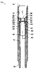
Fig. 1 is a side view in section of a drill string section with the check
valve;
Fig. 2 is a detailed side view in section of the lower piston of the second
check
valve;
Fig. 3 is a detailed side view in section of the first check; and
Fig. 4 is a perspective view of the upper piston.
DESCRIPTION OF PREFERRED EMBODIMENTS
[0006] In the claims, the word "comprising" is used in its inclusive sense and
does not
exclude other elements being present. The indefinite article "a" before a
claim feature does
not exclude more than one of the feature being present.

[0007] Referring to Fig 1, the check valve referred to generally by reference
numeral 10
is shown to include a section of drill string 12 that acts as a housing for
the check valve 10.
The drill string section is inserted in a drill string using an upper rotary
connection 14 and
lower rotary connection 16. Within drill string section 12 are two individual
check valves:
an inner or first check valve 18 and an outer or second check valve 20. The
check valves 16
and 18 are both positioned concentric with the drill string section 12, such
that each allows
flow in the same direction, but each allows fluid flow through a different
portion of the
cross-section of the drill string section 12. The second check valve 20 has an
annular shape,
such that the first check valve 18 is positioned within the second check valve
20. Thus, the


CA 02540499 2006-03-17

3
second check valve allows fluid flow through an outer portion of the cross-
section of the
drill string section 12, and the first check valve 18 allows flow through the
center portion of
the cross-section. This can be seen by referring to Fig. 4, the upper piston
22 of second
check valve 20 is shown, where the upper piston has outer openings 24
corresponding to
flow through second check valve 20, and a central opening 26 corresponding to
flow
through the first check valve 18. As two check valves 18 and 20 are used, the
pressure
threshold to open the valves may be set at different values, such that one
opens before the
other. For example, at lower pressures, only the first valve 18 may open, but
under
increased pressure, the second valve 20 would open to increase the flow
through check
valve 10. Alternatively, the second valve 20 may open at a lower pressure
threshold and
allow the fluid to bypass the first valve 18.

[0008] First and second check valves 18 and 20 can be any suitable type of
check valve,
such as flapper valves, piston valves, ball valves, poppet valves, etc. In the
embodiment
depicted in Fig. 1, the first check valve 18 is a flapper valve and second
check valve is a
piston valve, but it will be apparent to those skilled in the art that
substitutions may be made.
In addition, it will be apparent that the orientation of check valve 10 may be
reversed to
allow flow in the opposite direction.

[0009) Referring to Fig. 3, the first check valve 18 includes a flapper 28
positioned at the
bottom of the first check valve. Flapper 28 is biased in the closed position
by a spring (not
shown) at the hinge 30. In this embodiment, the first check valve 18 is
integrally formed
with the upper piston 22 of the second check valve 18, as both upper piston 22
and first
check valve 18 are designed to remain stationary. It will be understood that a
connection
between the two may be provided, such as a threaded connection or otherwise.
Referring to
Fig. 4, an embodiment is shown where the first check valve 18 is not
integrally formed with
the upper piston 22. The fluid applies pressure to the flapper 28 through the
central opening
26. Once the pressure is great enough to overcome the spring, flapper 28 opens
and permits
the fluid to flow. Surfaces 32 and 34 of the upper piston 22 are tapered to
reduce the effects
of the flow of an abrasive fluid. Referring to Fig. 1, the first check valve
18 is installed


CA 02540499 2006-03-17
4

within the drill string section 12 by threads 36 on upper piston 22 which
engage the inner
wall 37.

[0010] Referring to Fig. 1, second check valve 20 includes the upper piston
22, a lower
piston 38, and an inner sleeve 40 that is attached to the bottom of the upper
piston 22 by
threads 41 to hold it stationary. The lower piston 38 is positioned against
the inner wall 37
of the drill string section 12, such that it is free to move axially. The
axial movement of
lower piston 38 is limited by contact with a shoulder 42 inside lower piston
38 and the
bottom of inner sleeve 40 in one direction, and contact with a shoulder 43 on
the inner wall
37 and the bottom of the lower piston 38 in the other direction. The lower
piston 38 is
biased toward the inner sleeve 40 by a spring 44 in a cavity 46 formed by the
lower piston
38 and the inner wal137 of the drill string section 12. The cavity 46 is
sealed by o-ring seals
48 positioned on sections of the lower piston 38 above and below the cavity
46. An o-ring
seal 48 positioned on the inner sleeve 40 is also used to seal the connection
to the lower
piston 38. Instead of, or in addition to o-ring seals 48 on the inner sleeve
40, there may be
an o-ring seal 49 on the bottom of the inner sleeve 40. Alternatively, a
mating taper may be
used between the lower piston 38 and the inner sleeve 40. Instead of a spring
44,
pressurized fluid may also be used to bias the lower piston 38 toward the
upper piston 22 to
form a positive seal with the inner sleeve 40. If a pressurized fluid is used,
ports (not
shown) through the drill string section 12 into the cavity 46 may be used to
maintain or
otherwise control the pressure. As fluid pressure overcomes the force of the
spring 44, the
lower piston will be pushed down until an opening is created between the inner
sleeve 40
and the lower piston 38. The top surface 50 of the lower piston 38 is also
tapered to reduce
the effect of the flow of abrasive fluid through the second check valve 20. In
addition,
surfaces subject to the abrasive flow in both the first check valve 18 and the
second check
valve 20 may be hard coated, for example, with carbide. Other surfaces besides
those
shown may also be tapered to reduce the adverse effects of wear on the check
valve 10.

100111 Variations of the above embodiment include varying the components that
are
stationary and the components that reciprocate components. For example, the
upper piston


CA 02540499 2006-03-17

22 may reciprocate with the lower piston 38 being stationary, and first check
valve 18 may
reciprocate or be held stationary.

100121 Check valve 10 is assembled by inserting the lower piston 38 with the
spring 44
as shown in Fig. 2 into housing 12 as shown in Fig. 1. Referring to Fig. 3,
the inner sleeve
40 is attached to upper piston 22, as well as the first check valve 18 if not
integrally formed
with it. Referring again to Fig. 1, upper piston is secured by threads 41 to
the inner wall 37
of housing 12. If the housing 12 is a drill string section, it may then be
installed in a drill
string and be used in downhole applications.

[0013] Immaterial modifications may be made to the embodiments described here
without departing from the invention.

Dessin représentatif
Une figure unique qui représente un dessin illustrant l'invention.
États administratifs

Pour une meilleure compréhension de l'état de la demande ou brevet qui figure sur cette page, la rubrique Mise en garde , et les descriptions de Brevet , États administratifs , Taxes périodiques et Historique des paiements devraient être consultées.

États administratifs

Titre Date
Date de délivrance prévu Non disponible
(22) Dépôt 2006-03-17
(41) Mise à la disponibilité du public 2007-09-17
Demande morte 2012-03-19

Historique d'abandonnement

Date d'abandonnement Raison Reinstatement Date
2011-03-17 Absence de requête d'examen
2011-03-17 Taxe périodique sur la demande impayée

Historique des paiements

Type de taxes Anniversaire Échéance Montant payé Date payée
Le dépôt d'une demande de brevet 200,00 $ 2006-03-17
Taxe de maintien en état - Demande - nouvelle loi 2 2008-03-17 50,00 $ 2008-03-17
Taxe de maintien en état - Demande - nouvelle loi 3 2009-03-17 50,00 $ 2009-03-17
Taxe de maintien en état - Demande - nouvelle loi 4 2010-03-17 50,00 $ 2010-03-15
Titulaires au dossier

Les titulaires actuels et antérieures au dossier sont affichés en ordre alphabétique.

Titulaires actuels au dossier
LEEB, GERALD
Titulaires antérieures au dossier
S.O.
Les propriétaires antérieurs qui ne figurent pas dans la liste des « Propriétaires au dossier » apparaîtront dans d'autres documents au dossier.
Documents

Pour visionner les fichiers sélectionnés, entrer le code reCAPTCHA :


Pour visualiser une image, cliquer sur un lien dans la colonne description du document. Pour télécharger l'image (les images), cliquer l'une ou plusieurs cases à cocher dans la première colonne et ensuite cliquer sur le bouton "Télécharger sélection en format PDF (archive Zip)" ou le bouton "Télécharger sélection (en un fichier PDF fusionné)".

Liste des documents de brevet publiés et non publiés sur la BDBC .

Si vous avez des difficultés à accéder au contenu, veuillez communiquer avec le Centre de services à la clientèle au 1-866-997-1936, ou envoyer un courriel au Centre de service à la clientèle de l'OPIC.


Description du
Document 
Date
(yyyy-mm-dd) 
Nombre de pages   Taille de l'image (Ko) 
Abrégé 2006-03-17 1 17
Dessins représentatifs 2007-08-23 1 12
Description 2006-03-17 5 218
Revendications 2006-03-17 2 61
Dessins 2006-03-17 3 47
Page couverture 2007-09-07 1 39
Cession 2006-03-17 3 85
Correspondance 2006-04-20 1 46
Correspondance 2007-11-20 1 37
Correspondance 2008-03-17 2 44
Correspondance 2008-05-12 1 98
Correspondance 2008-05-14 1 13
Taxes 2008-03-17 1 28
Taxes 2009-03-17 1 39
Taxes 2010-03-15 1 25
Correspondance 2010-11-18 1 24
Correspondance 2011-05-12 1 70
Correspondance 2011-06-23 1 89