Sélection de la langue

Search

Sommaire du brevet 2540648 

Énoncé de désistement de responsabilité concernant l'information provenant de tiers

Une partie des informations de ce site Web a été fournie par des sources externes. Le gouvernement du Canada n'assume aucune responsabilité concernant la précision, l'actualité ou la fiabilité des informations fournies par les sources externes. Les utilisateurs qui désirent employer cette information devraient consulter directement la source des informations. Le contenu fourni par les sources externes n'est pas assujetti aux exigences sur les langues officielles, la protection des renseignements personnels et l'accessibilité.

Disponibilité de l'Abrégé et des Revendications

L'apparition de différences dans le texte et l'image des Revendications et de l'Abrégé dépend du moment auquel le document est publié. Les textes des Revendications et de l'Abrégé sont affichés :

  • lorsque la demande peut être examinée par le public;
  • lorsque le brevet est émis (délivrance).
(12) Brevet: (11) CA 2540648
(54) Titre français: SYSTEME ET PROCEDE POUR CORRIGER DES ERREURS DE PROFONDEUR SUR DES MESURES EFFECTUEES AU COURS D'UN FORAGE
(54) Titre anglais: SYSTEM AND METHOD FOR CORRECTING ERRORS IN DEPTH FOR MEASUREMENTS MADE WHILE DRILLING
Statut: Réputé périmé
Données bibliographiques
(51) Classification internationale des brevets (CIB):
  • E21B 47/04 (2012.01)
(72) Inventeurs :
  • ALDRED, WALTER (Royaume-Uni)
  • RINGER, MAURICE (Australie)
(73) Titulaires :
  • SCHLUMBERGER CANADA LIMITED (Canada)
(71) Demandeurs :
  • SCHLUMBERGER CANADA LIMITED (Canada)
(74) Agent: SMART & BIGGAR
(74) Co-agent:
(45) Délivré: 2012-10-30
(86) Date de dépôt PCT: 2004-09-28
(87) Mise à la disponibilité du public: 2005-04-14
Requête d'examen: 2009-09-09
Licence disponible: S.O.
(25) Langue des documents déposés: Anglais

Traité de coopération en matière de brevets (PCT): Oui
(86) Numéro de la demande PCT: PCT/GB2004/004123
(87) Numéro de publication internationale PCT: WO2005/033473
(85) Entrée nationale: 2006-03-29

(30) Données de priorité de la demande:
Numéro de la demande Pays / territoire Date
0322966.3 Royaume-Uni 2003-10-01

Abrégés

Abrégé français

La présente invention concerne un procédé et un système pour corriger automatiquement des erreurs de profondeur sur des mesures effectuées sur un train de forage au cours de la phase de forage de la construction d'un puits de forage d'hydrocarbures. La correction se base sur un profil de contrainte qui se base lui-même sur les états de l'appareil de forage, la spécification de longueur décrite par le train de forage, la trajectoire décrite par le trou de forage, le coefficient de frottement et le poids exercé sur le trépan.


Abrégé anglais


A method and system is disclosed for automatically correcting for depth errors
in measurements taken from a drillstring during the drilling phase of the
construction of a hydrocarbon wellbore. The correction is based on a stress
profile which in turn is based on the states of the drilling rig, drill string
description length spec, borehole description trajectory, friction factor and
weight on bit.

Revendications

Note : Les revendications sont présentées dans la langue officielle dans laquelle elles ont été soumises.


CLAIMS:

1. A method for automatically correcting for depth errors in measurements
taken from a drillstring comprising the steps of:

receiving data representing measurements taken in a hydrocarbon
wellbore at a plurality of depths within the wellbore from at least one sensor
located
on the drillstring used to drill the wellbore;

automatically calculating corrections for errors in the depths, wherein
said step of calculating corrections is based in part on estimates of stretch
of the
length of the drillstring; and

using the corrected depths to determine a depth of the measured data.
2. A method according to claim 1, wherein the step of automatically
calculating the corrections is based at least in part on the state of a
drilling rig used to
support the drillstring at the times when the measurements are taken.

3. A method according to claim 1 or 2, further comprising the step of
measuring the length of portions of the drillstring prior to insertion into
the wellbore.
4. A method according to claim 3, wherein a time versus depth log is
constructed using at least the measured length of portions of the drillstring.

5. A method according to claim 4, wherein the calculated corrections are
applied to time versus depth log to generate a corrected time versus depth
log, and
wherein the corrected time versus depth log is combined with the data
representing
measurements taken in the wellbore such that a corrected depth can be
attributed to
said measurements.

6. A method according to any one of claims 1 to 5, wherein said step of
calculating corrections includes the step of computing a hookload.


7


7. A method according to claim 6, wherein said step of calculating
corrections includes the step of computing a calculated hookload and varying
the
friction factor or the weight on bit until the hookload and the calculated
hookload
match.


8

Description

Note : Les descriptions sont présentées dans la langue officielle dans laquelle elles ont été soumises.


CA 02540648 2011-01-26
72424-109

SYSTEM AND METHOD FOR CORRECTING ERRORS IN DEPTH FOR
MEASUREMENTS MADE WHILE DRILLING

FIELD OF THE INVENTION:
The present invention relates to the field of
measurements made during the drilling phase of a
hydrocarbon borehole. In particular, the invention
relates to an automated method for correcting errors in
depth for such measurements.
1.0

BACKGROUND OF THE INVENTION:

During the drilling phase of the construction
of a hydrocarbon wellbore, the length of the drillstring
in the borehole is used to estimate the measured depth
(or along hole length) of a borehole, it is assumed that
the pipe is inelastic and therefore does not stretch.
However, discrepancies in the length of the borehole
estimated at surface during rig operations and the actual
length of the borehole there may cause gaps or lost data,
when the uncorrected depth is used with logs of data
measured with sensors mounted on the drillstring,

such as LWD and MWD logs.

SUMMARY OF THE INVENTION:

According to the invention,a method is provided
for automatically correcting for depth errors in
measurements taken from a drillstring comprising the
steps of receiving data representing measurements taken
in a hydrocarbon wellbore at a plurality of depths within

1


CA 02540648 2011-12-12
72424-109

the wellbore from at least one sensor located on the drillstring used to drill
the
wellbore, automatically calculating corrections for errors in the depths, and
using the
corrected depths to determine a depth of the measured data. The step of
calculating
corrections is based in part on estimates of stretch of the length of the
drill string.

BRIEF DESCRIPTION OF THE DRAWINGS:

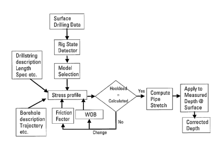
Figure 1 shows a scheme for correcting depth for measurements made
from a drillstring according to a preferred embodiment of the invention;

Figure 2 shows an example of data prior to correction according to a
preferred embodiment of the invention; and

Figure 3 shows data that has been corrected according to a preferred
embodiment of the invention.

DETAILED DESCRIPTION OF EMBODIMENTS:

The length of the drillstring in the borehole is used to estimate the
measured depth (or along hole length) of a borehole. According to the
invention, the
depth is corrected. For real drill strings the assumption that the drillstring
is inelastic
is not valid. The length of the drillpipe is a function of several parameters
including
temperature, pressure, and stress. According to the invention, corrections are
calculated based on at least the stress on the drillstring. In particular, a
correction is
calculated based on the un-deformed length of the drillstring and the stress
due to the
buoyant drillstring weight, weight on bit and frictional forces due to contact
with the
borehole acting along the length of the drillstring. Two of these parameters,
friction
factor and weight on bit vary depending on the rig operation and the drillers
input at
surface. According to the invention, a method is provided for correcting the
measurement of depth at

2


CA 02540648 2011-01-26
72424-109

surface for these parameters. The corrected depth is then used to assign
depths
to data measured downhole.

Figure 1 shows a scheme for correcting depth for measurements
made from a drillstring according to a preferred embodiment of the invention.
According to a preferred embodiment of the invention the following steps are
undertaken for each time step:

1) The drillstring description, dimensions pipe weight per unit length
are input, the pipe length as measured at surface is updated from real-time
measurements.

2) The borehole trajectory, inclination and azimuth are input and
updated from downhole measurements in real-time.

3) The rig operation is computed preferably as described in
US Patent No. 7,128,167 entitled "System and Method for Rig State Detection".
4) A model for computing the stress in the drillstring is selected.
5) A friction factor is selected for the given rig state.

6) Weight on bit is either estimated from the hookload and total
hookload or from weight on bit measured downhole.

7) From these inputs the model is used to compute the hookload. If
the hookload is within tolerances equal to the measured hookload the stress
profile is accepted and used to compute the pipe stretch. If it is not then
the
friction factor or the weight on bit are varied until the hookload and the
calculated
hookloads match. The models used here and in step 4 above preferably known
models such as DrillsafeTM.

3


CA 02540648 2011-01-26
72424-109

8) Pipe stretch is then computed using the stress profile.

9) The stretch correction is applied to measured depth to give the
corrected depth and time stamped.

10) Time stamped downhole data is the associated with the
corrected surface measured depths with the same time stamp.

Figure 2 shows an example of data prior to correction according to a
preferred embodiment of the invention. The first frame of Figure 2 shows a
surface time versus depth plot, the first section is drilling without surface
rotation.
As a result all of the friction force is opposing the motion of the
drillstring along the
hole. As a result whilst drilling the direction of the friction force is
towards surface.
The driller then stops the drill, pulls the drillstring off the bottom and
then runs
back to the bottom rotating the drillstring. When rotating, the friction force
opposes the direction of rotation and as a result the frictional force along
the
borehole falls to close to zero. This results in an increase in the tension in
the
pipe and therefore an increase in the pipe stretch. As a result the position
of the
bottom of the hole as measured from the surface appears shallower. In the
second frame the resistivity data are shown plotted against the same time
scale.
In the third frame the resistivity data are plotted against the apparent depth
at
which they were measured. It can be seen that there is a section of data in
lighter
grey that in terms of depths overlaps previously recorded data.
Conventionally,
these data would be discarded. The darker line represents the data that would
be
kept. Thus, failure to compensate for errors in depth results not only in lost
data
but also the thickness of the formation section appearing thinner.

4


CA 02540648 2011-01-26
72424-109

Figure 3 shows data that has been corrected according to a
preferred embodiment of the invention. The stress profile and the pipe stretch
have been calculated according to an appropriate model for the rig operation.
Note that in the first frame, the depth at which drilling resumes is very
close to the
depth at which it stopped. Secondly, the measured resisitivities are properly
allocated to the measured depth. Thus, according this embodiment of the
invention, there is no loss of data or gaps, (the remaining grey points are
recorded
off bottom).

While the invention has been described in conjunction with the
exemplary embodiments described above, many equivalent modifications and
variations will be apparent to those skilled in the art when given this

5


CA 02540648 2006-03-29
WO 2005/033473 PCT/GB2004/004123
disclosure. Accordingly, the exemplary embodiments of

the invention set forth above are considered to.be
illustrative and not limiting. Various changes to the
described embodiments may be made without departing from

the spirit and scope of the invention.
6

Dessin représentatif
Une figure unique qui représente un dessin illustrant l'invention.
États administratifs

Pour une meilleure compréhension de l'état de la demande ou brevet qui figure sur cette page, la rubrique Mise en garde , et les descriptions de Brevet , États administratifs , Taxes périodiques et Historique des paiements devraient être consultées.

États administratifs

Titre Date
Date de délivrance prévu 2012-10-30
(86) Date de dépôt PCT 2004-09-28
(87) Date de publication PCT 2005-04-14
(85) Entrée nationale 2006-03-29
Requête d'examen 2009-09-09
(45) Délivré 2012-10-30
Réputé périmé 2015-09-28

Historique d'abandonnement

Il n'y a pas d'historique d'abandonnement

Historique des paiements

Type de taxes Anniversaire Échéance Montant payé Date payée
Le dépôt d'une demande de brevet 400,00 $ 2006-03-29
Enregistrement de documents 100,00 $ 2006-05-25
Taxe de maintien en état - Demande - nouvelle loi 2 2006-09-28 100,00 $ 2006-08-04
Taxe de maintien en état - Demande - nouvelle loi 3 2007-09-28 100,00 $ 2007-08-07
Taxe de maintien en état - Demande - nouvelle loi 4 2008-09-29 100,00 $ 2008-08-07
Taxe de maintien en état - Demande - nouvelle loi 5 2009-09-28 200,00 $ 2009-08-07
Requête d'examen 800,00 $ 2009-09-09
Taxe de maintien en état - Demande - nouvelle loi 6 2010-09-28 200,00 $ 2010-08-09
Taxe de maintien en état - Demande - nouvelle loi 7 2011-09-28 200,00 $ 2011-08-05
Taxe finale 300,00 $ 2012-08-13
Taxe de maintien en état - Demande - nouvelle loi 8 2012-09-28 200,00 $ 2012-08-13
Taxe de maintien en état - brevet - nouvelle loi 9 2013-09-30 200,00 $ 2013-08-13
Titulaires au dossier

Les titulaires actuels et antérieures au dossier sont affichés en ordre alphabétique.

Titulaires actuels au dossier
SCHLUMBERGER CANADA LIMITED
Titulaires antérieures au dossier
ALDRED, WALTER
RINGER, MAURICE
Les propriétaires antérieurs qui ne figurent pas dans la liste des « Propriétaires au dossier » apparaîtront dans d'autres documents au dossier.
Documents

Pour visionner les fichiers sélectionnés, entrer le code reCAPTCHA :


Pour visualiser une image, cliquer sur un lien dans la colonne description du document. Pour télécharger l'image (les images), cliquer l'une ou plusieurs cases à cocher dans la première colonne et ensuite cliquer sur le bouton "Télécharger sélection en format PDF (archive Zip)" ou le bouton "Télécharger sélection (en un fichier PDF fusionné)".

Liste des documents de brevet publiés et non publiés sur la BDBC .

Si vous avez des difficultés à accéder au contenu, veuillez communiquer avec le Centre de services à la clientèle au 1-866-997-1936, ou envoyer un courriel au Centre de service à la clientèle de l'OPIC.


Description du
Document 
Date
(yyyy-mm-dd) 
Nombre de pages   Taille de l'image (Ko) 
Description 2006-03-29 6 214
Dessins 2006-03-29 3 55
Revendications 2006-03-29 2 57
Abrégé 2006-03-29 2 79
Dessins représentatifs 2006-06-07 1 8
Page couverture 2006-06-09 1 38
Description 2011-01-26 6 182
Revendications 2011-01-26 2 45
Revendications 2011-12-12 2 45
Description 2011-12-12 6 181
Page couverture 2012-10-09 1 39
Cession 2006-05-25 3 148
Correspondance 2006-05-25 1 48
PCT 2006-03-29 14 566
Cession 2006-03-29 2 83
Correspondance 2006-06-07 1 28
Cession 2006-06-23 1 40
Poursuite-Amendment 2009-09-09 1 45
Poursuite-Amendment 2010-06-02 1 44
Poursuite-Amendment 2010-08-02 2 65
Poursuite-Amendment 2011-01-26 13 470
Poursuite-Amendment 2011-06-13 2 46
Poursuite-Amendment 2011-12-12 6 199
Correspondance 2012-08-13 2 63
Correspondance 2014-12-18 2 329