Sélection de la langue

Search

Sommaire du brevet 2541640 

Énoncé de désistement de responsabilité concernant l'information provenant de tiers

Une partie des informations de ce site Web a été fournie par des sources externes. Le gouvernement du Canada n'assume aucune responsabilité concernant la précision, l'actualité ou la fiabilité des informations fournies par les sources externes. Les utilisateurs qui désirent employer cette information devraient consulter directement la source des informations. Le contenu fourni par les sources externes n'est pas assujetti aux exigences sur les langues officielles, la protection des renseignements personnels et l'accessibilité.

Disponibilité de l'Abrégé et des Revendications

L'apparition de différences dans le texte et l'image des Revendications et de l'Abrégé dépend du moment auquel le document est publié. Les textes des Revendications et de l'Abrégé sont affichés :

  • lorsque la demande peut être examinée par le public;
  • lorsque le brevet est émis (délivrance).
(12) Brevet: (11) CA 2541640
(54) Titre français: SUPPORT D'ECLAIRAGE TEMPORAIRE POUR SYSTEMES D'ECHAFAUDAGE
(54) Titre anglais: TEMPORARY LIGHTING SUPPORT ASSEMBLY FOR SCAFFOLDING SYSTEMS
Statut: Octroyé
Données bibliographiques
(51) Classification internationale des brevets (CIB):
  • F21V 21/08 (2006.01)
  • E04G 5/00 (2006.01)
(72) Inventeurs :
  • WHELAN, BRENDAN (Canada)
  • WHELAN, RICHARD (Canada)
(73) Titulaires :
  • WHELAN, BRENDAN (Canada)
(71) Demandeurs :
  • SUMAC FABRICATION CO. LTD. (Canada)
(74) Agent: WOODRUFF, NATHAN V.
(74) Co-agent:
(45) Délivré: 2010-07-20
(22) Date de dépôt: 2006-03-08
(41) Mise à la disponibilité du public: 2007-09-08
Requête d'examen: 2007-02-05
Licence disponible: S.O.
(25) Langue des documents déposés: Anglais

Traité de coopération en matière de brevets (PCT): Non

(30) Données de priorité de la demande: S.O.

Abrégés

Abrégé français

La présente invention concerne la fourniture d'un support d'éclairage temporaire pour échafaudage. Le support comprend deux composants principaux et les dispositifs de fixation nécessaires pour monter les boîtiers d'éclairage et les montants prévus dans deux configurations. Le support consiste en un premier tube à parois minces pourvu d'une demi-bride soudée à une extrémité et en un raccord en té à parois minces soudé à l'extrémité opposée. La bride et le té sont orientés de manière à optimiser le positionnement précis du support. Un second tube à parois minces est fixé à la pièce en té, perpendiculairement, de manière à former un cadre à angle droit. Le second tube est maintenu perpendiculairement au premier tube au moyen de deux bagues à rondelle soudées au-dessus et au-dessous du raccord en té, lequel maintient fermement les deux tubes l'un contre l'autre. Un petit espace aménagé entre la bague et le raccord en té permet au second tube de pivoter librement en rotation. Les cordons intégrés au support sont directement attachés à l'échafaudage pour des raisons de sécurité. Un autre aspect de l'invention concerne la demi-bride de tube, qui offre une possibilité d'assemblage rapide et une multitude de possibilités de positionnement sur les structures tubulaires horizontales ou verticales de l'échafaudage.


Abrégé anglais

The present invention is concerned with providing a support for temporary lighting for use with scaffolding systems. The support assembly comprises of two main components and the required fastening systems to affix lighting fixtures and mast light fixtures embodied in two configurations. The support consists of a thin walled pipe with a tube half clamp welded to one end and a thin walled tee welded to the opposite end. The clamp and tee are orientated to provide the support with a precise mounting position. A second thin walled pipe is positioned concentrically through the tee to create framework that has an angled appearance. The second pipe is maintained annular and concentric to the first pipe by means of two washer type collars welded above and below the tee that constrains both pipes to each other. A small space between the collar and tee provides the second pipe with unconstrained rotational movement. Lanyards incorporated in the support are fixed directly to the scaffold for job site safety concerns. Another aspect of the invention is the tube half clamp, which can provide quick assembly and infinite positional placement on a horizontal or vertical pipe member of a scaffolding system.

Revendications

Note : Les revendications sont présentées dans la langue officielle dans laquelle elles ont été soumises.


6
What is claimed is:


1. A support assembly for temporarily attaching lighting fixtures to
scaffolding systems, the
support assembly comprising:
an elongate support body;
a releasable clamp attached to the elongate support body for attaching the
elongate
support body to a scaffolding system; and
a bracket for adjustably securing a linear fixture to the elongate support
body.

2. The support assembly of claim 1, wherein the elongate support body
comprises a first
elongate portion and a second elongate portion, the second elongate portion
being connected to
the first elongate portion at an angle substantially perpendicular to the
first elongate portion,
the releasable clamp being connected to the first elongate portion, and the
means for attaching
the lighting fixture being connected to the second elongate portion.

3. The support assembly of claim 2, wherein the second end of the first
elongate portion
comprises a clamp for receiving the second elongate portion, the clamp
allowing the second
elongate portion to rotate and to move axially along its length.

4. The support assembly of claim 1, wherein a tether is attached to the
elongate support body,
the tether adapted to be attached to the scaffolding system to provide fall
arrest should the
releasable clamp fail.

5. The support assembly of claim 1, wherein the means for attaching a lighting
fixture
adjustably secures a mast fixture.

6. The support assembly of claim 1, wherein the bracket is secured using a
fastener that is
tightenable by hand.


7

7. The support assembly of claim 1, wherein the means for attaching the
lighting fixture to the
elongate support body is adjustable about an axis of rotation offset from and
substantially
parallel to the scaffolding system.

8. A support assembly for temporarily attaching lighting fixtures to
scaffolding systems, the
support assembly comprising:
an elongate support body, the support body comprising a first elongate portion
having a
first end and a second end, and a second elongate portion, the second elongate
portion being
connected to the second end of the first elongate portion at an angle
substantially perpendicular
to the first elongate portion;
a releasable clamp attached to the first end of the first elongate portion for
attaching the
elongate support body to a scaffolding system; and
a lighting fixture attachment connected to the second elongate portion, the
lighting
fixture comprising a bracket for adjustably securing a linear fixture.

9. The support assembly of claim 8, wherein the second end of the first
elongate portion
comprises a clamp for receiving the second elongate portion, the clamp
allowing the second
elongate portion to rotate and to move axially along its length.

10. The support assembly of claim 8, wherein a tether is attached to the
elongate support body,
the tether adapted to be attached to the scaffolding system to provide fall
arrest should the
release clamp fail.

11. The support assembly of claim 8, wherein the lighting fixture attachment
adjustably
secures a mast fixture.

12. The support assembly of claim 8, wherein the bracket is secured using a
fastener that is
tightenable by hand.

Description

Note : Les descriptions sont présentées dans la langue officielle dans laquelle elles ont été soumises.


CA 02541640 2007-06-18
1
TITLE
Temporary Lighting Support Assembly for Scaffolding Systems
FIELD OF THE INVENTION
This invention provides a method of setting up temporary lighting on job
sites, and
more specifically, by affixing the temporary lighting to a scaffolding system
by way of a
support assembly.

BACKGROUND OF THE INVENTION
It is common on job sites to have temporary lighting for the purpose of
carrying out
work in dark areas and at night. Temporary lighting around job sites in terms
of mounting
locations and ability to direct light to a precise location has used many time
consuming
makeshift solutions such as hanging fixtures from ropes and wires. The typical
way to affix
temporary lighting is to tie the fixture to overhanging beams and scaffolding
members by
means of rope or wire. Often light fixtures are located on a platform or
floor. This method of
affixing temporary lighting requires the appropriate personnel to attach the
rope or wire
through the lighting fixture and pull or lower it from a suitable platform
height to the location
the fixture is required. Additional stays are required to point the fixture in
the direction of the
work area. Tying the fixtures is time consuming and positioning requires
several steps. Rope
and wire shaping around the job site create additional safety issues. There is
little flexibility to
position a light fixture to illuminate a precise location as the ropes and
wire has several
rigidity issues.

SUMMARY OF THE INVENTION
To overcome the above disadvantages, I have determined that a support affixed
to the
surrounding scaffolding members using a scaffold tube half-clamp as its
attachment apparatus
provides a safer and quicker way to erect temporary lighting on the job site.
Since the support
fixture uses a scaffold half clamp it is well known to personnel on the job
site and therefore
can be readily implemented. The rotational ability of the support provides
flexibility to
illuminate a precise work area.


CA 02541640 2007-06-18

2
This invention with its use of a scaffold clamp as a mounting apparatus allows
quick
installation and precise location of the light direction. The invention has
the dual ability to
rotate the support assembly around the scaffold member plus the ability to
rotate the fixture
about an axis perpendicular to the scaffold axis the upward direction. Fine-
tuning of the light
fixture via rotation about the bracket gives the qualified person that
installs the light fixture
the ability to point the light in the final direction without having to
disturb the clamp
assembly. The pipe attached to the scaffold clamp is of a length that enables
the light fixture
to setback from the work platform of the scaffold system to avoid personnel on
the platform
from accidental collisions.

There is therefore provided a support assembly for temporarily attaching
lighting
fixtures to scaffolding systems. The support assembly comprises an elongate
support body
with a releasable clamp attached to the elongate support body for attaching
the elongate
support body to a scaffolding system. There is also provided means for
attaching a lighting
fixture to the elongate support body.

BRIEF DESCRIPTION OF THE DRAWINGS
These and other features of the invention will become more apparent from the
following
description in which reference is made to the appended drawings, the drawings
are for the
purpose of illustration only and are not intended to in any way limit the
scope of the invention to
the particular embodiment or embodiments shown, wherein:
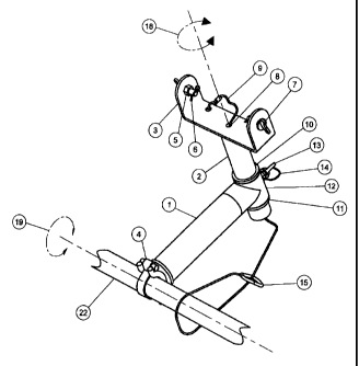
FIG. 1 is an isometric view of a temporary lighting support assembly.
FIG. 2 is an isometric view of a variation of the temporary lighting support
assembly
in FIG.1.
FIG. 3 is an elevation view of the temporary lighting support assembly in FIG.
1.
FIG. 4 is an elevation view of the temporary lighting support assembly in FIG.
2.
FIG. 5 is an isometric view of the attachment apparatus.


CA 02541640 2007-06-18

3
FIG. 6 is a rear isometric view of the temporary lighting support assembly
with a light
fixture mounted.
FIG. 7 is a front isometric view of the temporary lighting support assembly
with a
mast light fixture mounted.
FIG. 8 is a cross-section view of the intersection of pipes at the tee.
DETAILED DESCRIPTION OF THE PREFERRED EMBODIMENT
The invention illustrated comprises a support for a temporary lighting fixture
that
attaches itself to a horizontal scaffold pipe member 22 by means of a scaffold
clamp 4.
Scaffold clamp 4 is a steel clamp that can be obtained from several
manufactures that is
welded to pipe I in a precise orientation to upright the framework of the
support assembly in
the direction shown in FIG. 1 and 2. FIG. 1 and 2 show the attachment of the
support
assembly to a horizontal scaffold member 22. Rotation about axis 19 is
unlimited until the
preferred position is obtained and scaffold clamp 4 is secured. FIG. 5 shows
scaffold clamp 4
in the open state during the positioning of the support assembly as mentioned
above.
Mounting on vertical scaffold members is accomplished in the same manner as
horizontal
mounting.

FIG. 6 and 7 show that it is suitable for mounting a linear fixture 23 or mast
fixture
26. A steel thin walled tee 12 that is welded to a steel pipe 1 holds steel
pipe 2 captive but
allows free rotation of pipe 2 on axis 18. Two steel collar washers 10 and 11
are welded to
pipe 2. Collar 10 is welded as part of the manufacture of pipe 2 and collar 11
is welded in
place as part of the final assembly integration. A small space 32 shown on
FIG. 8 is sustained
to prevent binding of the collars to the tee. With this configuration full
rotation of pipe 2
around axis 18 is obtainable. A steel fixture bracket 3 in the embodiment of
FIG. 1 is welded
at the top of pipe 2 to receive linear type fixtures. Steel nuts 5 welded to
the inside of bracket
3 receive steel wing screws 7. Wing screw 7 is the mechanism used to tighten
the linear
fixture 23 after the final position is attained. A cotter pin 6 prevents wing
screw 7 from
backing out during linear fixture 23 fine-tuning or light fixture replacement.
Bracket 3 is
manufactured to specified dimensions. Linear fixture 23 is modified with the
addition of an


CA 02541640 2007-06-18

4
aluminum or steel ear 33 shown on FIG. 6 where two ears 33 are installed
symmetrically at
the back of linear fixture 23. Ears 33 fit closely but freely on the outside
of bracket 3. Linear
fixture 23 can rotate about axis 35 until the desired position is obtained,
wing screws 7 are
then hand tightened and linear fixture 23 is held in desired position.
Modifications to linear
fixture 23 are required with the addition of an aluminum or steel ear 34 to
connect lanyard
line 24 to bracket 3. When the linear fixture 23 is installed and the desired
positioned is
attained, free rotation about axis 37 of the entire pipe 2 assembly is still
possible. When the
desired position around axis 37 is achieved, a steel wing screw 13 is hand
tightened to hold
pipe 2 assembly in place. Lanyard 14 is attached to wing screw 13 to prevent
loss of said
screw. Lanyard 27 supplied with manufacturer's mast light 26 is tethered to
ring 29. Referring
to FIG. 1, lanyard 36 is tethered at one end of bracket 3 then feed through
the inside of pipe 2.
When the support is attached to a horizontal or vertical scaffold member
lanyard 36 is looped
around the scaffold member and a snap hook 15 is attached around the lanyard
wire to
provide fall arrest of the support assembly.
In the embodiment of FIG. 2, pipe 17 provides a mounting location for a mast
light
fixture 26 shown in FIG. 7. Mast light 26 is conventionally attached over a
pipe by a slip
fitting 38. The slip fitting 38 is tightened onto pipe 17 with manufacturer's
screws 39. When
the mast light is secured to pipe 17 free rotation is still possible around
axis 30. Wing screw
13 is tightened when the desired position is obtained. Lanyard 27 supplied
with
manufacturer's mast light 26 is tethered to ring 29. Likewise to the
embodiment of FIG. 1 the
embodiment of FIG. 2 shows lanyard 28 tethered at one end to ring 29 then feed
through the
inside of pipe 17. When the support is attached to a horizontal or vertical
scaffold member
lanyard 28 is looped around the scaffold member and a snap hook 15 is attached
around the
lanyard wire to provide fall arrest of the support assembly.

Pipe 1 in both FIG. 1 and 2 is at a length to have linear fixture 23 and mast
fixture 26
set back to a distance suitable to avoid intrusion of the fixture into the
platform areas of the
scaffolding system. If requirements dictate that intrusion into the platform
areas of the


CA 02541640 2007-06-18

scaffolding systems are necessary the support assembly is flexible enough too
fully rotate to
accommodate full positioning inside the platform area.

It will be noted that, although intended for tube-scaffolding systems, the
lighting
5 support assembly can be incorporated into purpose built mast light stands
and around
industrial and commercial sites where scaffolds tubes can be readily
installed.

In this patent document, the word "comprising" is used in its non-limiting
sense to mean
that items following the word are included, but items not specifically
mentioned are not
excluded. A reference to an element by the indefinite article "a" does not
exclude the possibility
that more than one of the element is present, unless the context clearly
requires that there be one
and only one of the elements.

It will be apparent to one skilled in the art that modifications may be made
to the
illustrated embodiment without departing from the spirit and scope of the
invention as hereinafter
defined in the Claims.

Dessin représentatif
Une figure unique qui représente un dessin illustrant l'invention.
États administratifs

Pour une meilleure compréhension de l'état de la demande ou brevet qui figure sur cette page, la rubrique Mise en garde , et les descriptions de Brevet , États administratifs , Taxes périodiques et Historique des paiements devraient être consultées.

États administratifs

Titre Date
Date de délivrance prévu 2010-07-20
(22) Dépôt 2006-03-08
Requête d'examen 2007-02-05
(41) Mise à la disponibilité du public 2007-09-08
(45) Délivré 2010-07-20

Historique d'abandonnement

Il n'y a pas d'historique d'abandonnement

Taxes périodiques

Dernier paiement au montant de 225,00 $ a été reçu le 2020-03-02


 Montants des taxes pour le maintien en état à venir

Description Date Montant
Prochain paiement si taxe applicable aux petites entités 2023-03-08 229,04 $
Prochain paiement si taxe générale 2023-03-08 458,08 $

Avis : Si le paiement en totalité n'a pas été reçu au plus tard à la date indiquée, une taxe supplémentaire peut être imposée, soit une des taxes suivantes :

  • taxe de rétablissement ;
  • taxe pour paiement en souffrance ; ou
  • taxe additionnelle pour le renversement d'une péremption réputée.

Les taxes sur les brevets sont ajustées au 1er janvier de chaque année. Les montants ci-dessus sont les montants actuels s'ils sont reçus au plus tard le 31 décembre de l'année en cours.
Veuillez vous référer à la page web des taxes sur les brevets de l'OPIC pour voir tous les montants actuels des taxes.

Historique des paiements

Type de taxes Anniversaire Échéance Montant payé Date payée
Le dépôt d'une demande de brevet 200,00 $ 2006-03-08
Requête d'examen 400,00 $ 2007-02-05
Enregistrement de documents 100,00 $ 2007-03-07
Taxe de maintien en état - Demande - nouvelle loi 2 2008-03-10 50,00 $ 2008-02-13
Taxe de maintien en état - Demande - nouvelle loi 3 2009-03-09 50,00 $ 2009-01-26
Taxe de maintien en état - Demande - nouvelle loi 4 2010-03-08 50,00 $ 2010-01-12
Taxe finale 150,00 $ 2010-01-29
Enregistrement de documents 100,00 $ 2010-06-25
Taxe de maintien en état - brevet - nouvelle loi 5 2011-03-08 100,00 $ 2011-01-03
Taxe de maintien en état - brevet - nouvelle loi 6 2012-03-08 100,00 $ 2011-12-19
Taxe de maintien en état - brevet - nouvelle loi 7 2013-03-08 100,00 $ 2012-12-17
Taxe de maintien en état - brevet - nouvelle loi 8 2014-03-10 100,00 $ 2014-03-10
Taxe de maintien en état - brevet - nouvelle loi 9 2015-03-09 100,00 $ 2014-12-18
Taxe de maintien en état - brevet - nouvelle loi 10 2016-03-08 125,00 $ 2016-02-12
Taxe de maintien en état - brevet - nouvelle loi 11 2017-03-08 250,00 $ 2017-03-06
Taxe de maintien en état - brevet - nouvelle loi 12 2018-03-08 125,00 $ 2018-02-26
Taxe de maintien en état - brevet - nouvelle loi 13 2019-03-08 125,00 $ 2019-03-01
Taxe de maintien en état - brevet - nouvelle loi 14 2020-03-09 125,00 $ 2020-03-02
Taxe de maintien en état - brevet - nouvelle loi 15 2021-03-08 225,00 $ 2020-03-02
Taxe de maintien en état - brevet - nouvelle loi 16 2022-03-08 225,00 $ 2020-03-02
Taxe de maintien en état - brevet - nouvelle loi 17 2023-03-08 236,83 $ 2023-03-07
Taxe de maintien en état - brevet - nouvelle loi 18 2024-03-08 236,83 $ 2023-03-07
Taxe de maintien en état - brevet - nouvelle loi 19 2025-03-10 236,83 $ 2023-03-07
Titulaires au dossier

Les titulaires actuels et antérieures au dossier sont affichés en ordre alphabétique.

Titulaires actuels au dossier
WHELAN, BRENDAN
Titulaires antérieures au dossier
SUMAC FABRICATION CO. LTD.
WHELAN, BRENDAN
WHELAN, RICHARD
Les propriétaires antérieurs qui ne figurent pas dans la liste des « Propriétaires au dossier » apparaîtront dans d'autres documents au dossier.
Documents

Pour visionner les fichiers sélectionnés, entrer le code reCAPTCHA :


Pour visualiser une image, cliquer sur un lien dans la colonne description du document. Pour télécharger l'image (les images), cliquer l'une ou plusieurs cases à cocher dans la première colonne et ensuite cliquer sur le bouton "Télécharger sélection en format PDF (archive Zip)" ou le bouton "Télécharger sélection (en un fichier PDF fusionné)".

Liste des documents de brevet publiés et non publiés sur la BDBC .

Si vous avez des difficultés à accéder au contenu, veuillez communiquer avec le Centre de services à la clientèle au 1-866-997-1936, ou envoyer un courriel au Centre de service à la clientèle de l'OPIC.


Description du
Document 
Date
(yyyy-mm-dd) 
Nombre de pages   Taille de l'image (Ko) 
Dessins représentatifs 2010-07-09 1 10
Page couverture 2010-07-09 2 50
Dessins 2009-05-01 8 85
Revendications 2009-05-01 2 71
Paiement de taxe périodique 2020-03-02 1 33
Abrégé 2007-06-18 1 28
Description 2007-06-18 5 214
Revendications 2007-06-18 3 77
Dessins représentatifs 2007-08-16 1 8
Page couverture 2007-08-28 1 46
Paiement de taxe périodique 2023-03-07 1 33
Abrégé 2006-03-08 1 28
Description 2006-03-08 3 177
Revendications 2006-03-08 1 45
Dessins 2006-03-08 8 86
Poursuite-Amendment 2007-06-18 12 400
Correspondance 2006-05-04 1 56
Correspondance 2006-05-04 1 40
Poursuite-Amendment 2010-02-11 1 29
Correspondance 2010-02-25 1 10
Poursuite-Amendment 2009-05-01 7 168
Cession 2006-03-08 2 85
Poursuite-Amendment 2007-02-05 1 28
Poursuite-Amendment 2007-02-22 1 89
Paiement de taxe périodique 2018-02-26 1 33
Correspondance 2007-03-12 1 48
Cession 2007-03-07 3 128
Correspondance 2007-04-12 1 23
Correspondance 2007-11-13 1 38
Taxes 2008-02-13 2 68
Correspondance 2008-02-13 2 68
Poursuite-Amendment 2009-03-16 2 70
Taxes 2009-01-26 1 32
Correspondance 2009-08-12 1 89
Poursuite-Amendment 2010-01-20 3 102
Poursuite-Amendment 2010-01-28 1 13
Correspondance 2010-01-29 1 29
Taxes 2010-01-12 1 29
Correspondance 2010-05-10 1 69
Cession 2010-06-25 4 133
Correspondance 2011-03-31 3 155
Correspondance 2011-06-02 1 11
Correspondance 2011-06-02 1 19
Paiement de taxe périodique 2017-03-06 1 33