Sélection de la langue

Search

Sommaire du brevet 2555897 

Énoncé de désistement de responsabilité concernant l'information provenant de tiers

Une partie des informations de ce site Web a été fournie par des sources externes. Le gouvernement du Canada n'assume aucune responsabilité concernant la précision, l'actualité ou la fiabilité des informations fournies par les sources externes. Les utilisateurs qui désirent employer cette information devraient consulter directement la source des informations. Le contenu fourni par les sources externes n'est pas assujetti aux exigences sur les langues officielles, la protection des renseignements personnels et l'accessibilité.

Disponibilité de l'Abrégé et des Revendications

L'apparition de différences dans le texte et l'image des Revendications et de l'Abrégé dépend du moment auquel le document est publié. Les textes des Revendications et de l'Abrégé sont affichés :

  • lorsque la demande peut être examinée par le public;
  • lorsque le brevet est émis (délivrance).
(12) Brevet: (11) CA 2555897
(54) Titre français: POT DE CHAUFFAGE SERVANT D'ACCESSOIRE A UNE BUSE D'INJECTION POUR SYSTEME DE MOULAGE PAR INJECTION
(54) Titre anglais: HEATING CYLINDER FOR ATTACHMENT TO AN INJECTION NOZZLE FOR AN INJECTION MOLDING SYSTEM
Statut: Octroyé
Données bibliographiques
Abrégés

Abrégé français

Pot de chauffage creux servant d'accessoire à une buse d'injection pour système de moulage par injection. Une cartouche de chauffage est enroulé en spirale sur l'extérieur du cylindre. La cartouche de chauffage contient deux conducteurs de chaleur pouvant être chauffés électriquement, qui sont électriquement séparés l'un de l'autre et qui sont situés dans différentes zones en direction longitudinale de la cartouche de chauffage. Un conducteur de chaleur est positionné de manière à chauffer la zone d'embouchure de la buse, alors que l'autre conducteur de chaleur est positionné de manière à chauffer la zone de la tige de la buse.


Abrégé anglais

A hollow heating cylinder for attachment to an injection nozzle for an injection molding system. An elongated heating cartridge is spirally wound on the outside of the cylinder. The heating cartridge contains two electrically heatable heat conductors which are electrically separated from one another and are located in different regions in the longitudinal direction of the heating cartridge. One heat conductor is positioned for heating the mouth region of the nozzle and the other heat conductor is positioned for heating the shank region of the nozzle.

Revendications

Note : Les revendications sont présentées dans la langue officielle dans laquelle elles ont été soumises.


In The Claims

1. A hollow heating cylinder for attachment to an injection nozzle for
an injection molding system, the heating cylinder having an elongated heating
cartridge wound spirally around the outside thereof, said heating cartridge
having
a first and a second electrically heatable heat conductor, said heat
conductors
being electrically separated from one another and being located in
substantially
different regions in the longitudinal direction of said heating cartridge,
said first
heat conductor being positioned for heating the mouth region of an injection
nozzle and said second heat conductor being positioned for heating the shank
region of an injection nozzle.

2. The hollow heating cylinder according to Claim 1, wherein said first
and second heat conductors have electrical connections which are positioned at
the
end of the heating cartridge opposite to said first heat conductor.

3. The hollow heating cylinder according to Claim 1 wherein said heat
conductors comprise spiral heating coils.

4. The heating cylinder according to Claim 1 wherein said heating
cartridge is positioned in a spiral groove on the outside surface of said
heating
cylinder.

5. The heating cylinder according to Claim 4, wherein said spiral
groove in the region adjacent said first heat conductor has a smaller pitch
than in
the remaining region.

8


6. The heating cylinder according to Claim 1 further comprising an
outer protective jacket surrounding said heating cylinder.

7. The heating cylinder according to claim 6 further comprising
longitudinal grooves in said protective jacket for positioning temperature
sensors
for the mouth and shank regions of the nozzles.

8. An injection molding system comprising at least one mold tool and
at least one injection nozzle, the improvement comprising a hollow heating
cylinder positioned on said injection nozzle, said hollow heating cylinder
having a
body member and an elongated heating cartridge spirally would around said body

member, said heating cartridge having a first heat conductor and a second heat

conductor positioned therein, said first and second heat conductors located in

different regions in the longitudinal direction of said body member.

9. The injection molding system according to claim 8 wherein said
body member has a spiral groove on the outer surface and said elongated
heating
cartridge is positioned on said spiral groove.

10. The injection molding system according to claim 9 wherein said
spiral groove has a first pitch for positioning of said first heat conductor
and a
second pitch different than said first pitch for positioning of said second
heat
conductor.

11. The injection molding system according to claim 9 wherein said first
and second heat conductors each comprise spiral heating coils.

9


12. The injection molding system according to claim 8 further
comprising a jacket member positioned over said hollow heating cylinder.

13. The injection molding system according to claim 12 further
comprising temperature sensor members positioned in said jacket member.


Description

Note : Les descriptions sont présentées dans la langue officielle dans laquelle elles ont été soumises.


CA 02555897 2006-08-08

HEATING CYLINDER FOR ATTACHMENT TO AN
INJECTION NOZZLE FOR AN INJECTION MOLDING SYSTEM
TECHNICAL FIELD

The present invention relates to heating cylinders for injection nozzles for
injection molding systems.

BACKGROUND OF THE INVENTION

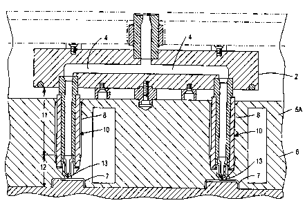
For understanding the problem underlying the present invention, reference
is made to Figures 1 and 2 of the drawings. Figure 1 shows an injection
molding
system, in schematic representation. From an injection molding machine
connected via a feed bushing 3, hot melt (i.e. molten plastic material) is
conducted
through the flow channels 4 of a heated hot-channel distribution block 2 to
two or
more nozzles 10. The injection nozzles 10 are positioned in accommodating
bores
8 in the injection-side member 5A of the mold tool 6. The injection nozzles
are
connected via the so-called mouth (or orifices) 13 to cavities 7, in which the
molded parts are formed and which are usually found in the ejection-side part
5B
of the too16.

There is a considerable difference between the required temperature of the
melt and that of the tool. For example, the processing temperature of the melt
can
be 250 C, while the tool can have a temperature of 50 C. This temperature
difference results in a considerable flow of heat away from the nozzles,
especially
at the points of contact between the nozzles and the tool. This heat loss must
constantly be compensated by heating of the nozzles. This heating is effected
by
1


CA 02555897 2006-08-08

means of heating cylinders capable of being attached to the nozzles, to which
the
present invention relates. The most critical point with regard to the risk of
overcooling of the melt is at the mouth 13, since here the heat-absorbing
capacity
of the surrounding nozzle material is small owing to the gradual reduction in
the
diameter of the nozzle and the fact that there is an intimate contact between
the
nozzle and the tool.

These conditions require that heating of the nozzle in the mouth region 12
must be greater than in the shank region 11. The heat supply required for this
in
the mouth region 12 is also heavily dependent upon the operating conditions,
the
material of the melt and the tool, and the shape of the mouth 13. In addition,
the
heat supply must be effectively controllable, since the range of the
processing
temperature of some melts is very narrow. In addition, in the cold state of
the tool
for example, a greater quantity of heat must be supplied to the mouth region
12.

It is already known that the nozzles may be equipped with two separate
heating cylinders 20A, 20B, as shown, for example, in Figure 2, specifically,
one
for the mouth region 12 and one for the shank region 11. The heat conductors
of
the two heating cylinders are capable of being controlled and/or regulated
independently of one another. The heating cylinders typically consist
essentially
of a hollow supporting cylinder, which is provided with a spiral groove for
the
accommodation of a heating cartridge, in which a heat conductor is embedded.
The pitch of the spiral groove on the supporting cylinder of the heating
cylinder
for the mouth region 12 is as a rule smaller than the pitch of the spiral
groove on
2


CA 02555897 2006-08-08

the supporting cylinder for the shank region 11. On the outside of the heating
cylinder is found a protective metallic jacket 23. In Figure 2, in addition to
the
illustration of the nozzle, the accommodating bore 8 in the tool is also
indicated.

One disadvantage of this known system is that two separate heating
cylinders 20A, 20B are required. An additional disadvantage is that the
electrical
connection 34 of the heating cylinder 20A for the mouth region lies quite far
in
front in the direction of the mouth, so that a corresponding longitudinal
groove 9
(Figure 2) must be provided for its accommodation in the bore 8 of the tool-
injection-side member 5A. This necessity, apart from the additional expense,
may
in some tools also result in problems of space. Moreover, a considerable risk
of
damage to the electrical connection 34 exists upon introduction of the nozzles
into
the accommodating bores 8 of the tool. In Figure 2, reference numeral 35A
designates the electrical connection to the temperature sensor for the heating
cylinder 20B. The corresponding temperature sensor for the heating cylinder
20A
is not shown.

SUMMARY OF THE INVENTION

The object of the present invention is to provide an improved heating
system for an injection machine nozzle.

The system according to the present invention utilizes only one heating
cylinder instead of two separate heating cylinders as known in present
systems.
With the present invention, an elongated heating cartridge is spirally wound
on the
outside of the hollow heating cylinder. The heating cartridge contains two
3


CA 02555897 2006-08-08

electrically heatable heat conductors which are electrically separated from
one
another and are located in essentially different regions in the longitudinal
direction
of the heating cartridge. One heat conductor is positioned for heating the
mouth
(orifice) region of the nozzle, while the other is positioned for heating the
shank
region of the nozzle. Hence the electrical connection 34, which in the prior
art
projects radially outward in the mouth region from the cylindrical member of
the
heating cylinder in the mouth region, is eliminated. Consequently, the
accommodating groove 9 for this connection in the nozzle-accommodating bore 8
of the tool may be omitted. In addition, the space requirement in the cable
channel
of the system is reduced, since only one ISO cable for two heating connections
is
required. With the present invention, considerable cost savings are achieved.

BRIEF DESCRIPTION OF THE DRAWINGS

The invention is to be described in detail with reference to the figures,
wherein:

Figure 1 shows a sketch of an injection molding system according to the
prior art.

Figure 2 depicts an injection nozzle with two separate heating cylinders
according to the prior art.

Figure 3 depicts an injection nozzle with an exemplary embodiment of a
heating cylinder according to the present invention.

Figure 4 illustrates an exemplary embodiment of a heating cartridge for a
heating cylinder according to the present invention.

4


CA 02555897 2006-08-08

Figure 5 illustrates an exempiary embodiment of a supporting cylinder for a
heating cylinder according to the present invention.

DESCRIPTION OF THE PREFERRED EMBODIMENTS

An exemplary embodiment of a heating cartridge according to the present
invention is shown in Figure 4. The cartridge 30 contains two heat conductors
32
and 33, which are wound to form spiral heating coils. The heating coils are
accommodated in a metal sleeve 31, in which they are embedded in a
conventional
electrically insulating compound 40. The heating coil 32 is in the front (tool-
side)
part Bl of the sleeve 31, while the heating coil 33, which is spatially and
electrically separated from the heating coil 32, is in the remaining portion
B2 of
the sleeve 31. The electrical connections 34 and 35 of the two heating coils
are
carried out of the metal sleeve 31 at the end opposite to the heating coil 32.

The heating cartridge 30 is long as compared with its diameter, which is not
readily apparent in Figure 4, which shows the structure of the heating
cartridge
only schematically. In practice, the cartridge 30 resembles a long plastically
deformable rod or wire and is wound on a hollow supporting cylinder, such as
exemplary cylinder 21 shown in Figure 5. For guidance of the heating cartridge
to
be wound, the outside of the supporting cylinder 21 is provided with a spiral
groove 22, which in its mouth-side region B 1 has a significantly smaller
pitch than
in its shank region B2. The lengths of the heating coils 32, 33 are adjusted
to the
supporting cylinder such that the windings of the spiral groove 22, lying
close
together in the mouth region B 1, are substantially received by the heating
coil 32,


CA 02555897 2006-08-08

and the windings of the spiral groove 22 in the shank region B2, provided with
a
greater pitch, are substantially received by the heating coil 33. The
connections 34
and 35 of the two heating coils are carried out of the heating cylinder 20 at
A
(Figure 5). Radially outside the supporting cylinder 21, provided with the
heating
cartridge 30, is positioned a protective jacket 23, not represented in Figure
5 but
indicated in Figure 3.

Figure 3 shows an injection nozzle 100 to which the hollow heating
cylinder 20 according to the invention is attached. It can be seen that the
complete
injection nozzle 100 does not have any parts projecting radially along its
entire
length, as does the known injection nozzle 10 of Figure 2. It can in addition
be
seen that the indicated accommodating bore 8 of the tool does not need the
groove
9 (see Figure 2) as required in the prior art. The electrical connections 34,
35 of
the two heating coils are at the end of the nozzle turned away from the tool,
and
are outside the accommodating bore 8. The thin connecting lines for the
temperature sensors in the mouth region and in the shank region lie,
respectively,
in a small longitudinal grooves 24 and 25 in the protective jacket 23, owing
to
which there is no expansion in the radial direction.

Heating, as in the prior art, may be controlled or regulated separately in the
mouth region and in the shank region of the nozzle. The greater thickness of
the
windings of the heating cartridge 30 on the supporting cylinder 21 in the
mouth
region B I is preferably but is not a requirement of the present invention,
However, it is advantageous, since if similar pitches in both regions are
utilized,
6


CA 02555897 2006-08-08

the current-carrying capacity of the heating coil 32 would have to be higher
than
that of the heating coil 33, with the consequence that the heating coils in
both
regions would have to be dimensioned electrically unlike.

While various embodiments of the invention have been shown and
described, numerous variations and alternate embodiments will occur to those
skilled in the art. Accordingly, it is intended that the invention be limited
only in
terms of the appended claims.

7

Dessin représentatif
Une figure unique qui représente un dessin illustrant l'invention.
États administratifs

Pour une meilleure compréhension de l'état de la demande ou brevet qui figure sur cette page, la rubrique Mise en garde , et les descriptions de Brevet , États administratifs , Taxes périodiques et Historique des paiements devraient être consultées.

États administratifs

Titre Date
Date de délivrance prévu 2010-02-02
(22) Dépôt 2006-08-08
Requête d'examen 2006-08-08
(41) Mise à la disponibilité du public 2008-02-08
(45) Délivré 2010-02-02

Historique d'abandonnement

Il n'y a pas d'historique d'abandonnement

Taxes périodiques

Dernier paiement au montant de 473,65 $ a été reçu le 2023-08-04


 Montants des taxes pour le maintien en état à venir

Description Date Montant
Prochain paiement si taxe générale 2024-08-08 624,00 $
Prochain paiement si taxe applicable aux petites entités 2024-08-08 253,00 $

Avis : Si le paiement en totalité n'a pas été reçu au plus tard à la date indiquée, une taxe supplémentaire peut être imposée, soit une des taxes suivantes :

  • taxe de rétablissement ;
  • taxe pour paiement en souffrance ; ou
  • taxe additionnelle pour le renversement d'une péremption réputée.

Les taxes sur les brevets sont ajustées au 1er janvier de chaque année. Les montants ci-dessus sont les montants actuels s'ils sont reçus au plus tard le 31 décembre de l'année en cours.
Veuillez vous référer à la page web des taxes sur les brevets de l'OPIC pour voir tous les montants actuels des taxes.

Historique des paiements

Type de taxes Anniversaire Échéance Montant payé Date payée
Requête d'examen 800,00 $ 2006-08-08
Enregistrement de documents 100,00 $ 2006-08-08
Le dépôt d'une demande de brevet 400,00 $ 2006-08-08
Taxe de maintien en état - Demande - nouvelle loi 2 2008-08-08 100,00 $ 2008-08-08
Taxe de maintien en état - Demande - nouvelle loi 3 2009-08-10 100,00 $ 2009-08-07
Taxe finale 300,00 $ 2009-11-17
Taxe de maintien en état - brevet - nouvelle loi 4 2010-08-09 100,00 $ 2010-07-08
Expiré 2019 - Taxe de paiement en souffrance, selon le par. 3.1(1) 50,00 $ 2011-08-18
Taxe de maintien en état - brevet - nouvelle loi 5 2011-08-08 200,00 $ 2011-08-18
Taxe de maintien en état - brevet - nouvelle loi 6 2012-08-08 200,00 $ 2012-07-27
Taxe de maintien en état - brevet - nouvelle loi 7 2013-08-08 200,00 $ 2013-07-17
Taxe de maintien en état - brevet - nouvelle loi 8 2014-08-08 200,00 $ 2014-08-04
Taxe de maintien en état - brevet - nouvelle loi 9 2015-08-10 200,00 $ 2015-08-03
Taxe de maintien en état - brevet - nouvelle loi 10 2016-08-08 250,00 $ 2016-08-01
Taxe de maintien en état - brevet - nouvelle loi 11 2017-08-08 250,00 $ 2017-08-07
Taxe de maintien en état - brevet - nouvelle loi 12 2018-08-08 250,00 $ 2018-08-06
Taxe de maintien en état - brevet - nouvelle loi 13 2019-08-08 250,00 $ 2019-08-02
Taxe de maintien en état - brevet - nouvelle loi 14 2020-08-10 250,00 $ 2020-07-31
Taxe de maintien en état - brevet - nouvelle loi 15 2021-08-09 459,00 $ 2021-07-30
Taxe de maintien en état - brevet - nouvelle loi 16 2022-08-08 458,08 $ 2022-07-29
Taxe de maintien en état - brevet - nouvelle loi 17 2023-08-08 473,65 $ 2023-08-04
Titulaires au dossier

Les titulaires actuels et antérieures au dossier sont affichés en ordre alphabétique.

Titulaires actuels au dossier
INCOE CORPORATION
Titulaires antérieures au dossier
EMICH, JUERGEN
Les propriétaires antérieurs qui ne figurent pas dans la liste des « Propriétaires au dossier » apparaîtront dans d'autres documents au dossier.
Documents

Pour visionner les fichiers sélectionnés, entrer le code reCAPTCHA :


Pour visualiser une image, cliquer sur un lien dans la colonne description du document. Pour télécharger l'image (les images), cliquer l'une ou plusieurs cases à cocher dans la première colonne et ensuite cliquer sur le bouton "Télécharger sélection en format PDF (archive Zip)" ou le bouton "Télécharger sélection (en un fichier PDF fusionné)".

Liste des documents de brevet publiés et non publiés sur la BDBC .

Si vous avez des difficultés à accéder au contenu, veuillez communiquer avec le Centre de services à la clientèle au 1-866-997-1936, ou envoyer un courriel au Centre de service à la clientèle de l'OPIC.


Description du
Document 
Date
(yyyy-mm-dd) 
Nombre de pages   Taille de l'image (Ko) 
Abrégé 2006-08-08 1 16
Description 2006-08-08 7 266
Revendications 2006-08-08 3 82
Dessins 2006-08-08 2 73
Dessins représentatifs 2008-01-17 1 32
Page couverture 2008-01-31 2 65
Page couverture 2010-01-13 2 65
Correspondance 2006-09-14 1 26
Cession 2006-08-08 3 115
Cession 2007-02-08 1 46
Taxes 2008-08-08 1 54
Correspondance 2009-05-27 1 30
Taxes 2009-08-07 1 48
Correspondance 2009-11-17 1 45