Note : Les descriptions sont présentées dans la langue officielle dans laquelle elles ont été soumises.
CA 02556312 2012-07-13
MACHINE FOR THE TRANSPORT OF TRACK SWITCHES, AND METHOD
The invention relates to a machine for the transport of track switches and the
laying thereof upon a ballast bed, consisting of a switch carrier comprising
cable
winches and fastening devices for connection to the track switch, the switch
carrier being supportable at each end by means of a respective on-track
undercarriage and crawler track on a track or a ballast bed.
A machine for the transport of track switches and the laying thereof upon a
ballast bed is known from US 4 249 467. At each end of a switch carrier
supporting the track switch, two on-track undercarriages and a crawler track
are
connected to the switch beam.
Further machines of a similar type are also known from DE 2 313 055, DE 3 419
205, FR 2 325 765 and DE 3 419 240.
It is the object of the present invention to provide a machine of the
specified kind
with which more versatile working operations are possible while taking into
account different construction site conditions.
According to the invention, this object is achieved with a machine of the type
mentioned at the beginning by means of the following features:
a) the on-track undercarriage and crawler track are connected to one another
in
each case by a common undercarriage frame,
b) the switch carrier is composed of a carrier mid-section, connected to the
cable
winches, and two carrier end-sections which are articulatedly connected at one
end to the carrier mid-section by means of a respective carrier joint and
supported on the undercarriage frame,
c) each of the two carrier end-sections is pivotable relative to the
undercarriage
frame about an undercarriage axis, extending parallel to a carrier axis of
the,
carrier joint and spaced from the same, by means of a rotation drive.
CA 02556312 2012-01-17
2
In an advantageous manner, a configuration of this kind enables both a
transporting of the switch from the manufacturing plant to the construction
site
and the laying of the switch upon the ballast bed, without requiring the use
of
special gantry cranes or the like. Owing to the three-part design of the
switch
carrier and the possibility of swinging the end parts thereof outwardly, a
problem-free laying down of switches is assured even on construction sites
where space is constrained, for example in tunnels.
The invention will be described in more detail below with reference to
embodiments represented in the drawing in which
Figs. 1 and 2 each show a side view of a respective half of a machine for
transporting and laying a track switch,
Figs. 3 and 4 each show a cross-section along section line III or IV in
Figs. 1 or 2,
Fig. 5 shows a top view of a part of the machine, and
Fig. 6 shows a further variant of embodiment.
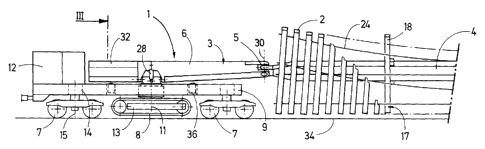
A machine 1, visible in Figs. 1 and 2, comprises a longitudinally extending
beam-
like switch carrier 3 for transporting a track switch 2. The switch carrier 3
is
composed of a carrier mid-section 4, supporting the track switch 2, and two
carrier end-sections 6, each of the latter being connected to the carrier mid-
section 4 by means of a carrier joint 5. Each of the carrier end-sections 6 is
mounted on an undercarriage frame 9 which is connected to two on-track
undercarriages 7 and a crawler track 8 positioned centrally between these. The
crawler track 8 is rotatable by means of a rotation drive 10 about an
undercarriage axis 11 and equipped with a motive drive 13 actuatable by a
motor
12. Each on-track undercarriage 7 is vertically adjustable relative to the
undercarriage frame 9 along a bogie pivot axis 15 by means of drive 14. A
respective vertically adjustable lifting ram 36 is fastened to the
undercarriage
frame 9 in each case between the on-track undercarriage 7 and the crawler
track 8.
As visible also in Figs. 3 and 4, cable winches 16 are arranged - one
following
the other in a longitudinal direction of the carrier or longitudinal axis 20 -
on the
carrier mid-section 4, the cable winches 16 being connected in pairs by means
of
CA 02556312 2012-01-17
3
a cable 19 to a fastening device 17 having the shape of a crossbeam 18. Each
crossbeam 18 has a centrally arranged opening 21 (see Fig. 4) for receiving a
centering pin 22 which is connected to and projects from the carrier mid-
section
4. Fixing clamps 23 connected to the crossbeam 18 have a hook 25 which can
be pushed under a rail 24 of the track switch 2 in a transverse direction
extending perpendicularly to the longitudinal direction 20 of the carrier.
As can be seen in Figs. 3, 4 and 5, the carrier end-section 6 is mounted for
pivoting about a pivot axis 26, extending in the longitudinal direction of the
carrier end-section, on a pivot support 27 connected to the undercarriage
frame
9. For pivoting, a pivot drive 28 is provided with the carrier section 6 and
the
pivot support 27. The pivot axis 26 is positioned centrally with respect to an
undercarriage axis 29 of the crawler track 8. A pivoting angle a (see Fig. 4)
is
delimited, on the one hand, by the transport position - indicated in dash-and-
dot
lines - and, on the other hand, by the laying position of the carrier end-
section 6.
The carrier joint 5 (in the laying position) has a carrier axis 30 extending
parallel
to the undercarriage axis 11 (Fig. 1,2). The distance between the carrier axis
30
and the undercarriage axis 11 is greater than the distance of the latter from
the
bogie pivot axis 15.
As indicated in Fig. 6, the carrier joint 5 may alternatively be distanced
relative to
the undercarriage axis 11 in the longitudinal direction 20 of the carrier by
means
of a telescopic drive 31 mounted in the carrier end-section 6. By means of a
counterweight section 32, the carrier end-section 6 is extended in the
direction
from the carrier axis 30 to the undercarriage axis 11 beyond the latter. For
improved effectiveness as a counterweight, the counterweight section 32 can be
distanced from the pivot axis 26 by means of a drive 33.
The mode of functioning of the machine 1 will now be described in more detail.
For picking up the track switch 2 lying adjacent to the track 34 in the
manufacturing plant, the machine I is moved in the transverse direction of the
track with the aid of the crawler tracks 8, rotated by 90 while the on-track
undercarriages 7 are raised, until the switch carrier 3 comes to lie above the
CA 02556312 2012-01-17
4
track switch 2. Parallel thereto, with the aid of the rotation drives 10 - and
the
pivoting of the carrier end-sections 6, induced thereby - changes in position
of
the carrier mid-section 4 are always possible for the precise centering of the
same above the track switch 2. With actuation of the cable winches 16, the
fastening devices 17 or crossbeams 18 are lowered, and the hooks 25 are
pushed under the rails 24 and anchored down. Now, the track switch 2 is raised
with the aid of the cable winches 16 until the centering pins 22 automatically
enter into the openings 21 of each crossbeam 18, and the latter are pressed to
an underside of the carrier mid-section 4.
The track switch 2, having thus been braced form-fittingly against the switch
carrier 3 in a very simple manner and without any auxiliary operations, is
subsequently moved in the transverse direction of the track onto the track 34
by
means of the crawler tracks 8 (with the help of suitable ramps). After
lowering
the on-track undercarriages 7 with the aid of the drives 14, the on-track
undercarriages 7 are set upon the track 34 while the crawler tracks 8 are
raised.
With actuation of the two pivot drives 28, the track switch 2 is pivoted,
together
with the switch carrier 3, into a transport position inclined by 60 to the
horizontal
(see Fig. 3). With this, even the very long sleepers of the track switch 2 are
still
positioned within the clearance gauge. Particularly in the case of tight track
curves or interfering obstacles, a transverse displaceability between
undercarriage frame 9 and carrier end-section 6 by means of a drive 37 makes
an adaptation to tight spots possible.
As soon as the construction site intended for placement and installation of
the
track switch 2 has been reached, the track switch 2 together with the switch
carrier 3 is pivoted back into the horizontal laying position (Fig. 4). If the
track
switch 2 is to be deposited directly adjacent to the track 34, the carrier end-
sections 6 are swivelled about the undercarriage axis 11 with actuation of the
rotation drives 10. As a consequence, the carrier mid-section 4 is also
shifted in
the transverse direction of the track together with the track switch 2, until
the
track switch 2 is positioned in its entirety adjacent to the track 34 (Fig.
5).
CA 02556312 2012-01-17
With actuation of the cable winches 16, the track switch 2 is deposited upon a
ballast bed 35, wherein it is still possibe at any time to carry out precise
position
adjustments by means of the rotation drives 10. As soon as the track switch 2
is
lying on the ballast bed 35, the hooks 25 are released, displaced transversely
on
the crossbeam 18 and lifted for insertion of the centering pins 22.
If the final position of the track switch 2 is not directly adjacent to the
track 34,
the machine 1 can be set down upon the two crawler tracks 8, rotated by 900
while the on-track undercarriages 7 are lifted, and moved in the transverse
direction of the track by means of the motive drives 13 until the unloading
position has been reached. Parallel thereto, the correct positioning of the
track
switch 2, particularly in constrained tunnel conditions, can be made
significantly
easier by suitable actuation of the rotation drives 10.
In order to facilitate the transfer of the machine 1 from the ballast bed 35
to the
track 34, the lifting rams 36 are pressed against the carrier end-section 6
(Fig.
2). With this, the on-track undercarriage 7 - preceding in the direction of
travel -
can be set on the track 34 without problems and without the use of ramps.
After
activation of the drive 14, the on-track undercarriage 7 is lowered and, as a
result, the crawler track 8 is raised.
With the machine 1 according to the invention, an unhindered transport of the
switch on a regular track as well as a problem-free laying down of the track
switch 2 in its installation position is possible in a particularly
advantageous
manner, wherein - for changing over from the transporting function to the
laying
function - no extensive retooling operations or additional auxiliary devices
are
required. The advantageous use of cable winches 16 notwithstanding, it is
possible by means of the centering pins 22 to achieve a very simple, quick and
effective connection between the switch carrier 3 and the track switch 2 for
the
safe transport thereof in an inclined position. At the construction site, the
track
switch 2 can be lowered immediately, while retooling operations are entirely
avoided which are made more difficult and dangerous by the heavy load. During
the lowering movement, precise positional corrections for an accurate switch
installation are possible at any time by slightly swivelling the carrier end-
sections
CA 02556312 2012-01-17
6
6. As a result of the simple, form-fitting bracing between the switch carrier
3 and
the track switch 2 - while avoiding rocking motions which stress the switch
and
are dangerous due to the heavy load - a problem-free transverse transport from
the track 34 to the installation site is assured.
As indicated in Fig. 6, it is optionally possible to elongate the carrier end-
section
6 with the aid of the drive 31. Also, the counterweight section 32 could be
distanced from the undercarriage axis 11 by means of the drive 33 in order to
increase the counterweight. Alternatively, the carrier joint 5 may also be
configured as a cross joint for universal moveability of the carrier sections
4,6
connected to one another.