Note : Les descriptions sont présentées dans la langue officielle dans laquelle elles ont été soumises.
CA 02558566 2006-09-O1
WO 2005/118035 PCT/GB2005/002094
UNtT DOSE DRY POItYDER If~HALER
BACKGROUND OF INDENTION
[0001 The field of the invention is dry powder inhalers.
[0002 Certain medicines maybe inhaled in dry powder form directly into the
lungs. inhalation bypasses the digestive system and avoids any potential
metabolic
inactivation or destruction of the medicine by the digestive system.
inhalation can
also provide very rapid onset of the. effect of the medicine. inhalation may
also
allow smaller doses to be used to achieve the same desired results as orally
ingested medicines. In other cases, it provides a delivery technique for
medicines
that display unacceptable side effects when taken by other methods. In
addition,
inhalation also avoids the potential. risks of injection to both .medical
caregivers and
patients.
(~00~~ Various inhaler designs have been proposed, to allow dry powder
~ 5 medicines to be inhaled. Most of these inhalers are metered dose inhalers
or
multiple dose dry powder inhalers. Metered dose inhalers dispense a suspension
of
powder particles in a compressed propellant gas. Multiple dose dry powder
inhalers
generally repeatedly dispense individual doses from a .bulk powder reservoir,
or from
a blister disk or cassette. However, certain medicines, such as certain
peptides .or
proteins, or medicines such as vaccines, antidotes, etc., are generally taken
by a
patient infrequently or even only one time. Metered dose inhalers.and multiple
dose
dry powder inhalers are not intended or well designed for one-time use, to
deliver a
1
CA 02558566 2006-09-O1
WO 2005/118035 PCT/GB2005/002094
single dose. These types of inhalers are typically too bulky, costly,
inefficient, or
difficult to use, when only a single dose is desired, and where the inhaler
can be
practically discarded after use, in an environmentally acceptable way.
[0004 Several unit dose inhalers, intended for one-time use, ~ have been
proposed. However, they have not achieved widespread use. Disadvantages
remain with unit dose inhalers relating to powder storage, dose uniformity,
dispersion perFormance, ease of use, cost, and other factors. Accordingly,
there is a
need for an improved inhaler for efficiently providing a single dose of a
powdered
drug.
it is an object of the invention to provide such an improved unit dose
dry powder inhaler.
S~JMNtAR~' f~F TI-!E 1~!~lEh6TlOl~.
~0006j A unit dose dry powder inhaler has a chamber. housing including a
dispersion chamber. An air filow passageway extends through the chamber
housing,
and through the dispersion chamber. A dose of a dry powder phar~mace.utical is
contained at a powder location on or in the chamber housing. A cover or cup
attached to the chamber housing is pivotable relative to the chamber housing
from a
first position, where the air flow passageway is closed off from the powder
location,
to a second position, where the air flow passageway connects through the
powder
location. The powder is stored directly within the inhaler itself. The.powder
can be
quickly and easily inhaled by twisting or turning the cover, to open up the
air flow
passageway through the powder location.
2
CA 02558566 2006-09-O1
WO 2005/118035 PCT/GB2005/002094
[00071 In a second aspect, the dispersion chamber contains one or more
beads, to~improve dispersion of the powder.
~OpOg, In a third aspect, a ratchet or anti-reverse movement device is
provided on the cover or the chamber housing, to help avoid inadvertent
attempts to
inhale a dose of powder from a used or empty inhaler.
~0009~ Other and further aspects and advantages are also described. The
invention resides as well in subcombinations of the components and method
steps
described and shown.
BRIEF DESCRIPTI~!~ OF T~iE DR,~Vhll\lt~S
~00~ ~~ In the drawings, wherein the same reference number indicates the
same element, in each of the views:
Fig. 1 is a top and front perspective view of a unit dose dry powder
inhaler.
~0012~ Fig. 2 is a bottom and rear perspective view of the inhaler shown in
Fig. 1.
~flO~gJ Fig. 3 is a perspective view similar to Fig. 1, and with the cover or
cup
removed, for purpose of illustration, to show the chamber housing.
~00~4~ Fig. 4 is a perspective view similar to Fig. 2, and with the cover or
cup
removed, for purpose of illustration, to show the chamber housing.
[00~15~ Fig. 5 is a bottom perspective view of the top or mouthpiece section
shown in Figs. 1-4.
3
CA 02558566 2006-09-O1
WO 2005/118035 PCT/GB2005/002094
[ODD 6j Fig. 6 is an inverted perspective view of the top section shown in
Fig.
5.
[Op~7j Fig. 7 is a top perspective view of the base section shown in Figs. 3
and 4.
[pQ~Sj Fig. 8 is a bottom perspective view of the base section, shown in Fig.
8.
[pp~gj Fig. 9 is a top perspective view of the cover element shown in Figs. 1
and 2.
[OOZOj Fig. 10 is plan view of the cover element shown in Fig. 9.
DE'~AILEC aESCRIPTIOt~ OF TEiE ~R~,~I~IGS
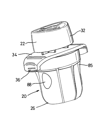
[002~j . Turning now in detail to the drawings, as shown in Figs. 1-4, an
inhaler
has a top or mouthpiece .section 22 rigidly attached to a base 24, to form a
chamber housing 100. A. cup or cover 26 fits over and is. pivotabiy attached
to the
chamber housing 100. The inhaler 20 is advantageously provided within a sealed
pouch or container 28 as shown in Fig. 2. The inhaler 20 is preferably removed
from
15 the pouch immediately before use, to better reduce adverse environmental.
affects
on the dose of powder.
[pg22j The fop section 22 includes a mouthpiece 32 extending out or up from
a finger grip plate 34. Finger tabs 36 on the finger grip plate 34 provide
convenient
and secure finger positions for holding the inhaler 20. As shown in Figs.
5.and 6, a
20 first or top curved chamber wall 42 is formed in the- underside of the
mouthpiece
section 22, opposite from the mouthpiece 32. A chamber tube 40 extends from a
central area of the chamber wall to or through the mouthpiece 32. A top
chamber
4
CA 02558566 2006-09-O1
WO 2005/118035 PCT/GB2005/002094
inlef groove 46 extends outwardly at an angle from the chamber wall 42. A snap
groove 52 is located along the lower edge of the top section 22. A top air
inlet 38
passes through the lower lip of the snap groove 52. A raised chamber rim or
shoulder 48 surrounds the chamber wall 42. Attachment holes 50 in the top
section
22 are used to attach and align the base 24 onto th.e top section 22.
~p023~ Referring now to Figs. 7 and 8, the base 24 has a flange 64 extending
radially outwardly from a cylinder section 65. A dose bowl or recess 74 is
formed in
the cylinder 65, and is surrounded by a bowl rim or raised shoulder 76. As
shown in
Fig. 3, a visual indicator 96, is provided on the outside of the cylinder,
opposite or
directly .across from the dose bow( 74. A flange inlet 68 and a flange outlet
63
extend through the flange 64, on opposite sides of the dose bowl 74.
Horizontal
spacer ribs. 94 project outwardly from the cylinder 65, opposite from the dose
bowl
74, and extend across an arc of 60-270, 90-210 or ~ ~ 0-~ 80 degrees. Ratchet
teeth
or recesses 71 and 73 are located about 90 degrees apart on or in the flange
64. A
stop tooth is sirnilarfy located about 90 degrees apart from the tooth 73 on
the flange
64. Attachment.pegs 70 extend up or out from the flange 64 for engagement into
the holes 50 in the top section 22. A curved second or bottom chamber wall 60
is
formed in the base 24 and is. surrounded by a raised bottom chamber rim 61. A
bottom chamber inlet groove 62 extends from the flange outlet 63 to the bottom
chamber wall 60.
~0024~ As shown in Figs. 3-8, the top or mouthpiece section 22 and the base
24 are joined together, with the pegs 70 in the holes 50. The top or first
chamber
s
CA 02558566 2006-09-O1
WO 2005/118035 PCT/GB2005/002094
wall 42 in the mouthpiece section 22 comes together with the second or bottom
chamber wall 60 in the base 24 to form a dispersion chamber, generally
indicated as
45 in Fig. 3. One or more beads 44 may optionally be contained within the
dispersion chamber 45. The raised top chamber rim 48 around the top chamber
wall 42 contacts with the raised bottom chamber rim 61 around the bottom
chamber
wall 60. The bottom chamber inlet groove 62 aligns with the top chamber inlet
groove 46, to form a chamber inlet passageway 69 connecting the flange outlet
63
with the dispersion chamber 45. The top or first air inlet 38 in the
mouthpiece section
22 is permanently fixed in position or aligned over the flange inlet 68 in the
base.
The mouthpiece section 22 and the base 24 may be joined via adhesives,
welding,
pressing, or .with other known techniques. The beads 44, if used, are placed
into the
dispersion chamber 45 before the mouthpiece section and the base are
permanently and irrotatably joined together. ~llhen joined together, the
mouthpiece
section 22, the base 24, and the bead or beads 44 (if used), form the chamber
housing 100.
fpp25l Turning to Figs. 9 and 10, a snap ring projection 90 is formed on the
inside diameter of a cover flange 80. A cover inlet slot 82 and a cover outlet
slot 84
are formed in the cylindrical sidewall of the cover. The slots 82 and 84 are
located
on the cover and dimensioned so that they can be aligned respectively with the
flange outlet 63 and the flange inlet 68 in the flange 64 of the base 24. One
or more
ribs 85 are preferably provided on the outside cylindrical walls of the cover
26. A
ratchet arm 98 is formed on the lip 99 of the cover 26. A dose loading hole 88
is
6
CA 02558566 2006-09-O1
WO 2005/118035 PCT/GB2005/002094
provided in the cylindrical sidewall of the cover, opposite from the slots 82
and 84.
As shown in Fig. 2, the bottom of the cover 26 is flat or has a central
concave area,
to allow the inhaler 20 to stand upright on a flat surface.
~0026~ Referring to Figs. 3, 4, 9 and 10, the cover 26 is attached to the
mouthpiece section 22 via the snap ring 90 snapping into the groove 52. The
inhaler
20 is then assembled, as shov~m in Figs. 1 and 2, and is ready for loading
with a
single dose 92 of a dry powder pharmaceutical.
[0~27~ The mouthpiece section 22, the base 24 and the cover 26 are
preferably molded of a plastic material, allowing them , to be manufactured
inexpensively, using a minimum amount of material. Molding also allows for
convenient formation or' various of the features described above. However,
various
other manufacturing techniques, invalving forming the mouthpiece section, base
and .
cover as integral components; or involving making them via assembly of
discrete
sub-components, may of course also be used:
1,5 [Oo~281 llVith the inhaler 20 init~aliy assembled, the dose loading hole
88 is
aligned over the dose bowl 74, and the inhaler 20 is laying on its side, with
the dose
bowl facing up. A dose of a dry powder pharmaceutical powder 92 is placed into
the
bowl, through the hole 88, preferably using an automated powder loading
system.
The cover 26 is then turned or rotated by about 90 degrees. This moves the
bowl 74
containing the powder 92 to a midpoint between the loading hole 8S and the
slots 82
and 84. The inhaler 20 is thus in the storage position, and may be sealed into
the
CA 02558566 2006-09-O1
WO 2005/118035 PCT/GB2005/002094
pouch or package 28 and sealed. In the storage position, the flange inlet 68
and the
flange outlet 63 to the bowl 74 are closed off by the cover flange 80.
[0029 The smooth cylindrical inside surface of the bow( 74 slides over the
bowl rim 76. The bowl rim 76 helps to contain the powder within the bowl. The
spacer ribs 94 space the inside cylindrical walls of.the cover apart from fhe
outside
cylindrical walls of the cylinder 65 on the base 24. Consequently, the bowl
makes
sliding contact only with the bowl rim 76 and the spacer ribs 94. The bowl
therefore
remains aligned on the cylinder 65,~ and rotates only when a desired amount of
turning force or torque is applied. This prevents inadvertent turning of the.
bowl
during packaging, shipment and handling. However, it also allows the bowl to
turn
when nominal force is applied, so that users with low hand and finger strength
or
dexterity are able to use the inhaler.
[p~~~) In use, the inhaler 20 is removed from, the package 28. The user
grasps the finger tabs 36 with one hand and rotates the cover by about'/4 turn
or 90
degrees, to an open position. The ratchet arm 98 allows the cover to be
rotated only
in the forward direction (counterclockwise in Fig. 2). The ratchet arm may
also
provide an audible and/or tactile click or pop when the open position is
reached. A
detent or an open position stop pin or boss may also be provided, to help
insure that
the cover is correctly and fully moved into the open position. The visual
indicator 96
is aligned in the dose loading opening 88, providing a visual indication to
the user
that the inhaler is in the open or ready to use position.
8
CA 02558566 2006-09-O1
WO 2005/118035 PCT/GB2005/002094
[003~~ The pivoting movement of the cover 26 opens the air flow
passageways in the inhaler 20. A first air flow path is formed via the top or
first inlet
38 and the flange inlet 68, which are permanently open. A second air flow path
is
formed by the flange outlet 63, the chamber inlet 69, the dispersion chamber
45,
and the chamber tube 40. With the inhaler in the storage position, the first
airflow
path is closed off from the second air flow path by the lip 99 of the cover
26, as the
slots 80 and 82 are not aligned with the openings 63 and 68 in the flange 64.
When
the cover 26 is turned further into the open or ready position, as described
below,
the first and second air flow paths are connected through the bowl 74 and the
slots
82 and 84 in the sidewall of the cover 26.
[003~~ In the open position, .the flange inlet 68 and outlet 63 to the bowl 74
are now open, as they are aligned with the slots 82 and 84 in the cover, 26
Thus, in
the open position, there is an unobstructed continuous air flow path through
the
inhaler. The user inhales on the mouthpiece 32. Air flows in the top inlet 38,
through
the flange outlet 63, into the cover inlet slot 82, through the bowl 74, and
then out of
the bowl through the cover outlet slot 84, the flange inlet 68, and into the
dispersion
chamber 45 via the chamber inlet passageway 69. As air flows through or over
the
bowl 92, powder is entrained in the air. The inlet and outlet slots 82 and 84
connect
tangentially into the bowl 74. This provides a swirling air movement, to
enhance
entrainment of the powder into the flowing air.
[0033 The airlpowder mixture flows into the dispersion chamber, where the
powder is more effectively dispersed, to provide better inhalation
performance.
9
CA 02558566 2006-09-O1
WO 2005/118035 PCT/GB2005/002094
Dispersion in the chamber 45 occurs via rapid circular movement of the powder
and
air. In embodiments containing beads in the chamber, the beads assist in
dispersion, as described in U.S. Patent No. 6,427,688 and U.S. Published
Patent
Application No. 2001/0027790A1, both incorporated herein by reference.
~0034~ Air and dispersed powder flow out of the dispersion chamber 45
through the chamber tube 40 and mouthpiece 32, and are inhaled by the user.
Sheath air channels 54 may be provided around the chamber tube, to surround
the
powder-laden stream of inhaled air with ambient air. Use .of sheath air
reduces
. . deposition of powder in the mouth and throat, so that more of the powder
is
delivered into the lungs of the user.
~0035~ After use, the cover 26 is optionally rotated an additional '/ turn,
into a
used or discard position. The stop boss or pin 75 engages with the ratchet arm
98, .
to prevent. the cover from turning in either direction. Accordingly, in the
used
position, the cover is locked and cannot turn, and the visual indicator 96 is
not
visible. This indicates to the user that the inhaler is used and should be
discarded.
Hence, turning the cover into the used position helps to prevent attempts to
inhale a
dose from a used inhaler.
[0036 The specific size, shape and arrangement of various of the features
shown Figs. 1 and 2, including the finger plate 34 and tabs 36, mouthpiece 32,
ribs
85; and the cover 26, is. arbitrary. The appearance of these features is a
matter of
design preference from a large array of options. These features may be
selected or
changed to create any desired ornamental external appearance of the inhaler
20.
to
CA 02558566 2006-09-O1
WO 2005/118035 PCT/GB2005/002094
[0037 Thus, a novel unit dose dry powder inhaler has been shown and
described. P~/lany changes, substitutions and uses of equivalents may of
course be
made without departing from the spirit and scope of the invention. The
invention,
therefore, should not be limited, except by the following claims and their
equivalents.
11