Note : Les descriptions sont présentées dans la langue officielle dans laquelle elles ont été soumises.
CA 02560764 2006-09-21
WO 2006/011913 PCT/US2005/006.161
FIBER OPTIC DROP CABLES SUITABLE FOR OUTDOOR FIBER TO THE
SUBSCRIBER APPLICATIONS
FIELD OF THE INVENTION
The present invention relates generally to fiber optic
drop cables. More specifically, the invention relates to low-
cost fiber optic drop cables having enhanced performance
characteristics for preserving optical performance in outdoor
applications such as fiber to the subscriber.
BACKGROUND OF THE INVENTION
Communication networks are used to transport a variety of
signals such as voice, video, data transmission, and the like.
Traditional communication networks use copper wires in cables
for transporting information and data. However, copper cables
have drawbacks because they are large, heavy, and can only
transmit a relatively limited amount of data. Consequently,
optical waveguide cables replaced most of the copper cables in
long-haul communication network links, thereby providing
greater bandwidth capacity for long-haul links. However, most
communication networks use copper cables for distribution
and/or drop links on the subscriber side of the central
of f ice . In other words, subscribers have a limited amount of
available bandwidth due to the constraints of copper cables in
the communication network. Stated another way, the copper
cables are a bottleneck that inhibit the subscriber from
utilizing the relatively high-bandwidth capacity of the long-
hauls links.
As optical waveguides are deployed deeper into
communication networks, subscribers will have access to
increased bandwidth. But there are certain obstacles that make
it challenging and/or expensive to route optical
waveguides/optical cables deeper into the communication
network, i.e., closer to the subscriber. For instance, laying
the last mile of fiber to the subscriber requires a low-cost
fiber optic cable that is craft-friendly for installation,
connectorization, slack storage, and versitilty Moreover, the
I
CA 02560764 2006-09-21
WO 2006/011913 PCT/I1S2005/006461
reliability and robustness of the fiber optic cable must
withstand the rigors of an outdoor environment.
Fig. 1 schematically illustrates two different methods
for routing fiber optic cables to a premises 19.
Specifically, Fig. 1 shows a first method of routing a figure
eight cable 10 to premises 19 in an aerial application and a
second method using a cable 10' routed to premises 19 in a
buried application. In aerial applications, cable 10 may be a
figure-eight cable having a first end 10a that is attached at
a first interface device 12 located on pole 11 and a second
end lOb that is merely a portion of cable 10 that is routed to
an interface device 14 at premises 19. Specifically, figure-
eight cables have a messenger section and a carrier section
that can be split apart near premises 19. More specifically,
IS messenger section can include a conductive strength member for
carrying the tensile load of cable 10 and is terminated and
attached with a clamp positioned at a tie point 19a of
premises 19. Carrier section of figure-eight cable 10
includes one or more optical fibers therein and is routed
along a side of premises 19 to interface device 14. In buried
applications, the first and second ends of cable 10' are
respectively routed to pedestal 18 and connected to interface
device 16 and routed and connected to interface device 14.
One such figure-eight drop cable is disclosed in U.S.
Pat. No. 6,546,175 and preferably has a carrier section that
does not include strength members. The carrier section of
this cable is flexible when split from the messenger section
for slack storage; however, the carrier section does not have
anti-buckling members so the polymer materials of ,the carrier
section may shrink with environmental temperature changes,
thereby causing elevated levels of optical attenuation.
Another figure-eight drop cable is disclosed in U.S. Pat. No.
6,356,690 having a carrier section with strength members that
provide anti-bucking to the carrier section. Strength members
may be a material such as steel that aids in inhibiting the
shrinkage of the carrier section; however, the steel strength
members make the carrier section relatively stiff, thereby
2
CA 02560764 2006-09-21
WO 2006/011913 PCT/US2005/006461
inhibiting slack storage. In other words, the strength
members increase the bending radius of the carrier section and
when coiled the strength members act like a coiled spring that
wants to unwind. Moreover, the potential for elevated
attenuation still exists.
Cables have used other strength members such as
conventional fiberglass yarns, but they provide less anti-
buckling strength than rigid strength members. U.S. Pat. No.
6,487,347 discloses an optical cable using conventional
l0 fiberglass yarns; however, the cable requires a relatively
large number of flexible strength members for adequate
performance. The use of a relatively large number of
conventional fiberglass yarns increases the manufacturing
complexity, increases the cost of the cable, and makes the
I5 cable relatively stiff. Thus, this cable does not meet all of
the requirements for a drop cable that is suitable for routing
optical waveguides to the subscriber.
BRIEF DESCRIPTION OF THE FIGURES
20 Fig. 1 schematically illustrates two methods for routing
a fiber optic drop cable to a premises.
Fig. 2 is a cross-sectional view of a figure-eight fiber
optic drop cable according to the present invention.
Fig. 3 is a cross-sectional view of another figure-eight
25 fiber optic cable according to the present invention.
Fig. 4 is a bar graph depicting an average shrinkage
during an average shrinkage test for a carrier section of the
figure-eight fiber optic cable in Fig. 3 after being separated
from the messenger section along with a variation of the cable
30 in Fig. 3 and the average shrinkage for similar separated
carrier sections of conventional figure-eight fiber optic drop
cables.
Figs. 5 and 6 respectively are a line graph and a bar
graph depicting an average coefficient of thermal expansion
35 (CTE) for the carrier section of the cable in Fig. 3 after
being separated from the messenger section along with a
variation of the cable in Fig. 3 and the CTEs for similar
3
CA 02560764 2006-09-21
WO 2006/011913 PCT1US2005/006461
separated carrier sections of conventional figure-eight fiber
optic drop cables.
Fig. 7 is a bar graph depicting maximum delta attenuation
for the cable of Fig. 3 and a similar conventional fiber optic
cable during thermal cycling testing at a reference wavelength
of 1550 nm.
Fig. 8 is a bar graph depicting maximum delta attenuation
for a cable similar to Fig. 3 except it included twelve
optical fibers therein and a similar conventional fiber optic
l0 cable during thermal cycling testing at a reference wavelength
of 1550 nm.
Fig. 9 is a cross-sectional view of another fiber optic
cable configuration according to the concepts of the present
invention.
Fig. 10 is a cross-sectional view of yet another fiber
optic cable configuration according to the concepts of the
present invention.
DETAILED DESCRIPTION OF THE INVENTION
The present invention will now be described more fully
hereinafter with reference to the accompanying drawings
showing preferred embodiments of the invention. The invention
may, however, be embodied in many different forms and should
not be construed as limited to the embodiments set forth
herein; rather, these embodiments are provided so that the
disclosure will fully convey the scope of the invention to
those skilled in the art. The drawings are not necessarily
drawn to scale but are configured to clearly illustrate the
invention.
Illustrated in Fig. 2 is an exemplary figure-eight drop
cable 20 (hereinafter cable 20) according to one embodiment of
the present invention. Cable 20 includes a messenger section
22 and a carrier section 24 having at least one roving 23 and
at least one optical waveguide 25 therein. As depicted,
optical waveguides 25 are loose, but they may have other
configurations. Messenger section 22 has a messenger jacket
4
CA 02560764 2006-09-21
WO 2006/011913
PCT/US2005/006461
28a and carrier section 24 has a carrier jacket 28b connected
by a web 28c. Web 28c also includes a preferential tear
portion 28d to aid in separation of carrier and messenger
sections 22,24. Messenger section 22 also includes a strength
component 26 for carrying tensile loads applied to cable 20.
Strength component 26 is shown as a steel rod, but it may be a
stranded wire. Additionally, cables of the present invention
can include a strength component as disclosed in U.S. Pat.
App. Ser. No. 10/623,231 filed on July 18, 2003 titled "Fiber
Optic Cable having a Strength Member", the disclosure of which
is incorporated herein by reference. Likewise, other suitable
materials such as dielectrics or other conductive materials
are possible for strength component 26. In this embodiment,
carrier section 24 also includes a tube 27 for housing at
least one optical waveguide 25. Fig. 3 shows a similar cable
20', which is a tubeless configuration. Additionally, rovings
23 of cable 20' are embedded within carrier jacket 28b, which
may further improve performance characteristics of the cable.
Cables 20 and 20' may also include other suitable components
such as a plurality of ripcords (not shown), thereby allowing
the craftsman to easily remove carrier jacket 38b from carrier
section 34. Likewise, cables 20 and 20' may include a
thixotropic material for water-blocking or they can
alternatively have a dry construction. other suitable cable
components include tapes and yarns having as water-swellable
or flame-retardant characteristics, armor, binder threads for
fiber bundles or securing tapes, or any other suitable cable
component.
As depicted in Fig. 2, cable 20 includes two rovings 23
generally aligned on a plane A-A that generally passes through
strength component 26 and web 28c. In other words, rovings 23
are disposed at six o'clock and twelve o'clock positions,
thereby imparting a preferential bend characteristic to cable
20. But, of course, other suitable positions for rovings 23
and/or other suitable numbers of rovings 23 are~possible using
the concepts of the present invention. For instance, cables
according to the present invention can have more than two
5
CA 02560764 2006-09-21
WO 2006/011913
PCT/US2005l006461
rovings 23; however, cables requiring fewer rovings
advantageously reduce material costs for the cable. Cables of
the present invention preferably have four or fewer rovings
23, more preferably two rovings 23, but other suitable numbers
of rovings 23 may be used with the concepts of the present
invention. Providing a reliable low-cost cable is advantageous
since drop cables will generally have relatively low optical
waveguide counts and require large length quantities to
provide access for many subscribers. Moreover, providing
access for many subscribers is labor intensive, thereby making
it relatively expensive. Thus, cable costs should be
relatively low for drop cables.
Cables according to the present invention provide a low
cost drop cable having enhanced performance characteristics
for preserving optical performance in outdoor applications
such as fiber to the subscriber. Moreover, cables according
to the present invention accomplish superior performance
levels because unlike conventional cables they provide
improved anti-buckling performance in a flexible design. For
instance, when carrier section 24 is separated from messenger
section 22 in cable 20, the carrier section 24 generally has a
lower average shrinkage and a lower average coefficient of
thermal expansion (CTE) compared with conventional cables.
Consequently, in figure-eight cable designs carrier
section 24 can be separated from messenger section 22 while
maintaining a maximum delta attenuation of optical waveguides
25 at about 0.3 dB/20 meters or less, more preferably about
0.1 dB/20 meters or less during temperature cycling at a
reference wavelength of 1550 nm at a temperature of about
-40°C after heat aging at 70°C. On the other hand,
conventional figure-eight cables have elevated levels of
shrinkage and/or CTE when the carrier and messenger section
are separated, thereby causing elevated levels of optical
attenuation. Thus, conventional figure-eight cables are
generally inoperable for aerial or buried applications where
the carrier and messenger sections are separated.
Additionally, cables according to the present invention have a
6
CA 02560764 2006-09-21
WO 2006/011913
PCT/US20051006461
relatively low-cost since a relatively large number of
strength members are not required as with conventional cables.
Moreover, cables according to the present invention are craft-
friendly for connectorization and slack storage making them
highly desirable for fiber to the subscriber applications.
Cables of the present invention have at least one roving
23 that comprises a plurality of glass fibers 23a having a
resin matrix 23b thereon. In preferred embodiments, glass
fibers 23a are an e-glass, but other suitable types of glass
l0 fibers can be used for roving 23. Glass fibers 23a are about
90°s or more by weight and resin matrix 23b is about 10~ or
less by weight. In preferred embodiments, glass fibers
comprise about 93~ or more by weight, and more preferably
about 95%, and resin matrix is about 7~ or less by weight,
more preferably about 5~. Resin matrix 23b comprises a water-
based acrylic composition that includes an ethylene-acrylic
acid. Suitable rovings 23 are available from Neptco,
Incorporated of Pawtucket, Rhode Island under the RPLPE
tradename.
Several different experiments were conducted to
investigate the performance of figure-eight cables according
to the present invention compared with conventional figure-
eight cables having a similar construction. The cables of the
present invention and the conventional cables had similar
constructions and processing parameters expect where noted
otherwise. Specifically, the cables of the experiments
included either four or twelve SMF-28e single-mode optical
fibers commercially available from Corning, Incorporated in a
polybutylene terephtalate (PBT) buffer tube having a 2.85 mm
OD and a 2.05 mm ID. The cables were manufactured with an
excess fiber length of about 0Ø The tested figure-eight
cables differed in that the conventional cables included
either two or four fiberglass strands available from Owens-
Corning, Incorporated under the tradename CR-785. On the
other hand, the tested cables of the present invention
included rovings 23 which were from NEpTCO Incorporated under
the tradename RPLPE 675. The strength components of the
7
CA 02560764 2006-09-21
WO 2006/011913
PCT/US20051006461
messenger sections were a solid steel rod. Additionally, the
jackets of all of the cables were formed from the same medium-
density polyethylene (NmpE) .
Fig. 4 is a bar graph depicting an average shrinkage
during an average shrinkage test for five different carrier
sections that were separated from the messenger section of
respective figure-eight drop cables. The average shrinkage
test measured the average shrinkage by taking a 1 meter sample
of the respective carrier sections that were separated from
the messenger section of the respective figure-eight cables.
Thereafter, the respective 1 meter carrier sections were
placed in a thermal chamber set at about 70°C for at least
thirty minutes and then removed and allowed to cool to an
ambient room temperature of about 20°C. Then, the respective
lengths of the carrier sections were measured and an average
shrinkage was calculated as a percentage for the respective
carrier samples of the respective figure-eight cables. Since
the average shrinkage of the carrier section was measured, the
number of optical waveguides in the carrier section is
irrelevant to the average shrinkage, but the number of optical
waveguides in the carrier section can affect the delta
attenuation during temperature cycling.
For a baseline comparison, a carrier section of a figure
eight cable that did not include any anti-buckling members was
tested and is represented by bar 40. The baseline carrier
section represented by bar 40 was different from the other
cables tested because it had a buffer tube with an OD of about
2.5mm, compared with the OD of 2.85 mm for the buffer tubes of
the other cables. As shown, bar 40 depicts an average
shrinkage of about 1.5% for this carrier section. It was
discovered that this carrier section had extremely high
maximum delta attenuation levels during temperature cycling at
a reference wavelength of 1550 nm. Maximum delta attenuation
during temperature cycling was on the order of 20.0 dB/20
meters and higher at about -40°C for the construction depicted
in bar 40, which had twelve optical waveguides within the
tube. Consequently, the carrier section represented by bar 40
8
CA 02560764 2006-09-21
WO 2006/011913
PCT/US2005/006461
was unsuitable for separation from the messenger section
because of the extremely high delta attenuation levels.
Bars 42 and 44 respectively represent carrier sections of
figure-eight cables having two and four conventional
fiberglass strands. The embodiment depicted by bar 42 had two
fiberglass strands that were disposed about 180 degrees apart.
As shown, bar 42 depicts an average shrinkage of about 0.9%
for the carrier section. In the embodiment depicted by bar
44, the carrier section included four fiberglass strands. The
fiberglass strands were disposed about 18o degrees apart in
adjacent groups of two. As shown, bar 44 depicts an average
shrinkage of about 0.6% for the carrier section. Thus,
including fiberglass strands decreased the average shrinkage
compared with the carrier section of bar 40.
Moreover, the average shrinkage was further decreased by
increasing the number of fiberglass strands from two to four;
however, this increases the material cost and manufacturing
complexity for the cable. Maximum delta attenuation during
temperature cycling for the configurations of bars 42 and 44
were respectively on the order of 0.6 dB/20 meters and 0.08
dB/20 meters at a reference wavelength of 1550 nm at about
-40°C, with twelve optical waveguides in the carrier section.
Generally speaking, higher maximum delta attenuations were
observed when twelve optical waveguides were disposed within
the carrier section compared with carrier sections having four
optical waveguides within a similar carrier section. The
conventional cable represented by bar 42 was on the design
bubble since the shrinkage and maximum delta attenuation was
an average value and some manufactured cables would be
acceptable and others would fail, thereby reducing yield and
requiring testing of each cable manufactured. The
conventional cable represented by bar 44 (the conventional
figure-eight cable having four fiberglass strands) had better
performance for both the average shrinkage test and the
maximum delta attenuation temperature cycling compared with
the conventional cable of bar 42, but it increased the cost of
the cable and is requires a more complex manufacturing
9
CA 02560764 2006-09-21
WO 20061011913
PCT/US2005/006461
operation. Additionally, it is possible for some of the
conventional cables represented by bar 44 to fail due to,
among other things, variability in the manufacturing process.
Bars 46 and 48 respectively represent carrier sections of
figure-eight cables according to the present invention having
two and four rovings 23. The embodiment depicted by bar 46
had two rovings 23 disposed about 180 degrees apart. As
shown, bar 46 depicts an average shrinkage of about 0.5% for
the carrier section. In the embodiment depicted by bar 48,
the carrier section included four fiberglass strands. The
four fiberglass strands were disposed about 180 degrees apart
in adjacent groups of two. As shown, bar 48 depicts an
average shrinkage of about 0.2% for the carrier section.
Thus, carrier sections of figure-eight cables according to the
present invention decreased the average shrinkage compared
with the respective embodiments of bars 42 and 44. More
surprisingly, maximum delta attenuation during temperature
cycling for the configurations of bars 46 and 48 were
respectively on the order of 0.03 dB/20 meters and 0.01 dB/20
meters at a reference wavelength of 1550 nm at about -40°C.
Thus, the figure-eight cables of the present invention yielded
surprising results compared with similar conventional figure-
eight cables tested.
Optical waveguides 25 of the present invention preferably
have an excess fiber length (EFL) that is about 0%. However,
there are practical limits on the amount of EFL that can be
used in a buffer tube or cavity of a tubeless cable.
Generally speaking, all things being equal, the larger the
inner diameter (ID) the more space that is available for EFL.
However, placing more optical waveguides in the tube or cavity
decreases the available space for EFL and can affect optical
performance. Figure-eight cables of the present invention
preferably have an EFL in the range of about 0 . 9 % to about
0.03% in a tube or cavity. By way of example, a tube or
cavity of a cable according to the present invention has an ID
of about 4 mm or less, more preferably about 2 mm, with 12 or
fewer fibers and an EFL of about 0.1% or less. 'But, of course
CA 02560764 2006-09-21
WO 2006/011913
PCT/US2005/006461
other suitable EFLs, IDs, or numbers of fibers are possible
with cables of the present invention. For instance, a tube or
cavity of a cable can have an ID of about 6mm or less, more
preferably about 2-3 mm, and include 24 fibers and an EFL of
about 0.1% or less. Additionally, the percent difference
between the average carrier shrinkage and the EFL is about
0.9% or less, more preferably about 0.5% or less, and most
preferably about 0.3% or less. For instance, if an average
shrinkage of the carrier section is 0.5% and the EFL is 0.1%
the difference therebetween is 0.4%.
Fig. 5 is a line graph depicting a thermal shrinkage of
four carrier sections separated from a messenger section over
a predetermined temperature range. Calculating the slope of
the lines in Fig. 5 yields a coefficient of thermal expansion
(CTE) for the respective carrier section. The first two
carrier sections depicted in Fig. 5, respectively represented
by lines 52 and 54, had the same constructions as the two
carrier sections having two and four fiberglass strands
depicted in Fig. 4. The second two carrier sections,
respectively represented by lines 56 and 58, had the same
construction as the two carrier sections having two and four
rovings 23 according to the present invention depicted in Fig.
4.
The thermal shrinkage test measured the thermal shrinkage
of a carrier section of a figure-eight cable that was
separated from the messenger section over the temperature
range of about -6o°C to about 70°C. The thermal shrinkage
test measured a 20 meter sample of the respective figure-eight
cables prior to separating the respective carrier sections.
Specifically, the respective cables were marked at their
midpoints and at respective intervals of 1 meter. Thereafter,
the carrier sections were separated from the messenger section
and attached to a kiln-dried board having markings disposed 1
meter apart along the length. Specifically, the markings on
the respective carrier sections were aligned with the markings
on the board at a first end of both. At the first end, the
carrier section was fixed so that it was unable to move, but
11
CA 02560764 2006-09-21
WO 2006/011913
PCT/US2005/006461
the rest of the carrier section was free to shrink along the
linearly attached length. Next, the board and carrier we
placed into a thermal chamber and length measurements of the
carrier section were measured as the temperature was varied
over the temperature range. The results were then plotted
obtain Fig. 5. Fig. 6 is a bar graph summarizing the slopes of
the lines of Fig. 5 which are the respective CTE for the
tested carrier samples in the thermal shrinkage test. As
shown in Table 1, the carrier sections of the figure-eight
drop cables of the present invention surprisingly have a much
smaller CTE, than comparable carrier sections of the
conventional cables. Specifically, bar 66 has a CTE that is
about 55~ of the CTE of bar 62 and bar 68 has a CTE that is
about 57% of the CTE of bar 64. Thus, the carrier sections of
cables of the present had an average coefficient of thermal
expansion (CTE~ of the carrier section of about 5.0 X 10⁻³ %/°C
or less, and more preferably, the CTE is about 4.0 X 10⁻³ %/°C
or less.
Table 1-CTE values for Fig. 6
8~tr CTE
62 0.009
64 0.007
66 0.005
68 0.004
Additionally, cables of the present invention can be
advantageously coiled without inducing elevated levels of
attenuation due to their relatively low-shrinkage in the
carrier section. In other words, if a coiled figure-eight
cable has elevated levels of shrinkage in the carrier section,
the carrier section of the coiled cable tends to rotate to the
inner diameter of the coil, thereby causing elevated levels of
attenuation. Figure-eight cables of the present invention
generally do have this problem so that they are suitable for
coiling for slack storage.
Fig. 7 depicts a bar graph showing maximum delta
attenuations for the cable of Fig. 3 and a similar
conventional fiber optic cable during thermal cycling testing
12
CA 02560764 2006-09-21
WO 2006/011913
PCT/US2005/006461
at a reference wavelength of 1550 nm having, Likewise, Fig, g
is a bar graph depicting maximum delta attenuation for a cable
similar to Fig. 3 except it included twelve optical fibers
therein and a similar conventional fiber optic cable during
thermal cycling testing at a reference wavelength of 1550 nm.
This temperature cycling was performed per the test procedures
of ICEA 717/ S-87-717, ANSI/ S-87-640, and FOTP-3 with added
measurements for the cables of the present invention at -50°C
and -60°C to examine performance at these ultra-low
temperatures. However, Figs. 7 and 8 merely illustrate the
interesting temperature cycling stages, namely, low
temperature performance before heat aging and low temperature
performance after heat aging.
The maximum delta attenuation testing was performed by
taking a 60 meter sample of cable and separating a 20 meter
carrier section of the cable roughly centered in the middle of
the length. Hence, the maximum delta attenuation is reported
for a length of 20 meters, rather than the typical value of
dB/km. The separated carrier section was placed in a
temperature chamber through suitable portals and the
temperature cycling according to the above mentioned test
procedure was initiated. Optical measurements were made using
a suitable optical source and power meter. Some of the
maximum delta attenuation values for Figs. 7 and 8 are
relatively low and are represented by small bars on Figs. 7
and 8 that are not drawn to scale. Tables 2 and 3
respectively summarize the values of the maximum delta
attenuations for Fig. 7 and Fig. 8 and have units of dB/20m.
Table 2-~aximtun Delta Attenuation Values for 4-fiber carrier sections of
Fig. 7
Cable 1S 19 Heat
n
2nd
-40 Agiag _
C -60C 2
20
C
-50C
_40
Conventional0 C
00 _60
C
. 0.00 0.61 1.64
Present -- -- __
Invention -001 0.00 -0.01 -0.01 0
00
.
0.00 0.01
13
CA 02560764 2006-09-21
WO 2006/011913
PCT/US2005/006461
T~lg 3-Maxixnum
Delta Attenuation
Valu
es for 12-fiber carrier sections
Fig. 8 of
Cable 180 18 Heat 2nd n
'
-40 C -60C Aging 2
-20 C
-50C
-40
Conventional0 C
00 - _60C
. 0.00 0.81 2.01
Present - -- __
Invention -0.02 -0.01 -0.02 0.00 0
01
.
0.02 0.02
As shown by both Figs. 7 and 8, the performance of the
carrier sections of the conventional cables and the cables of
the present invention have a similar performance before heat
aging at 70°C. However, after heat aging the carrier sections
of the present invention show a drastic difference in delta
to attenuation. As shown in both Figs. 7 and 8, the optical
performance of the conventional cables degrade at low
temperatures after heat aging, thereby making them unsuitable
for splitting the carrier section from the messenger section
in outdoor applications. On the other hand, the carrier
15 sections of the present invention have surprisingly low delta
attenuation levels. Specifically, optical waveguides in
cables of the present invention preferably have a maximum
delta attenuation of about 0.3 dB/20 meters or less, and more
preferably about 0.1 dB/20 meters or less, at a reference
20 wavelength of about 1550 nm at a temperature of about -40°C
after heat aging at 70°C. Additionally, the cables of present
invention maintain these performance levels down to a
temperature of about -60°C after heat aging.
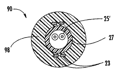
Other cable configurations besides figure-eight cables
25 are advantageous with the present invention. For instance,
Fig. 9 depicts cable 90 according to the present invention.
Cable 90 includes at least one optical waveguide 25', a buffer
tube 27, a plurality of rovings 23, and a cable jacket 28. In
other embodiments, the four rovings 23 of cable 90 can be
30 embedded at generally symmetrically locations as well as any
other suitable configurations. Optical waveguides 25' are
single-mode optical fibers that have a buffer layer (not
numbered); however, other types or configurations of optical
fibers can be used. For example, optical fibers 25 can be
14
CA 02560764 2006-09-21
WO 2006/011913
PCT/US2005/006461
mufti-mode, pure-mode, erbium doped, polarization-maintaining
fiber, other suitable types of light waveguides, and/or
combinations thereof. For instance, each optical fiber 25 can
include a silica-based core that is operative to transmit
light and is surrounded by a silica-based cladding having a
lower index of refraction than the core. Additionally, one or
more coatings can be applied to optical fiber 25. For
example, a soft primary coating surrounds the cladding, and a
relatively rigid secondary coating surrounds the primary
coating. The coating can also include an identifying means
such as ink or other suitable indicia for identification
and/or an anti-adhesion agent that inhibits the removal of the
identifying means. Additionally, optical waveguides 25 can be
disposed in ribbons or bundles as shown in Fig. 10. Suitable
optical fibers are commercially available from Cornin
Inco g
rporated of Corning, New York.
Buffer tube 27 is preferably constructed of a polymeric
material and is suitably dimensioned for receiving the optical
waveguides therein. However, other suitable materials and
shapes can be used for buffer tube 27. Buffer tube 27 of the
present invention can also include additives for improving
flame-retardance; however, any other suitable additives can be
used. Additionally, tube 27 can be, for example, extruded as
a continuous unit or be manufactured from one or more
polymeric flat tapes that are formed and sealed, thereb
Y
forming. the buffer tube. Additionally, buffer tube 27 can
have other suitable components or features such as a water-
swellable material thereon or a ripcord within a tube wall.
Likewise, cable jacket 28 is preferably constructed from a
suitable polymeric material. ' Moreover, cable jacket can
include ripcords embedded therein.
Fig. 10 depicts a cable 100 according to the present
invention. Cable 100 is similar to cable 90, except it is a .
tubeless design. As depicted, cable 100 include a fibe
r optic
ribbon 105 and a plurality of optical waveguides 25 in a
bundle. Generally speaking, excluding the tube in cable 100
results in less expensive material cost for cable 100.
CA 02560764 2006-09-21
WO 2006/011913 PCT/US2005/006461
Cables of the present invention can also be
preconnectorized in a factory environment, thereby simplifying
field installation to the subscriber. For instance, cables
can include at least one fiber optic connector as disclosed in
U.S. Pat. App. Ser. No. 10/765,428 filed on January 27, 2004
titled "Preconnectorized Fiber Optic Drop Cables and
Assemblies", the disclosure of which is incorporated herein by
reference. Of course, the concepts of the present invention
are also advantageous for cables not used for drop
applications to the premises such as fiber to the curb (FTTC)
applications.
Many modifications and other embodiments of the present
invention, within the scope of the appended claims, will
become apparent to a skilled artisan. For example, cables
according to the present invention may have high fiber counts
using optical waveguides can be formed in ribbons that are
stacked in suitable configurations such as a stepped profile.
Cables according to the present invention can also include
more than one cable stranded, thereby forming a breakout
cable. Therefore, it is to be understood that the invention
is not limited to the specific embodiments disclosed herein
and that modifications and other embodiments may be made
within the scope of the appended claims. Although specific
terms are employed herein, they are used in a generic and
descriptive sense only and not for purposes of limitation.
The invention has been described with reference to silica-
based optical waveguides, but the inventive concepts of the
present invention are applicable to other suitable optical
waveguides and/or cable configurations.
16