Note : Les descriptions sont présentées dans la langue officielle dans laquelle elles ont été soumises.
CA 02563771 2006-10-19
WO 2005/103395 PCT/US2005/012909
TIP FOR DEMOLITION AND CONSTRUCTION EQUIPMENT
BACKGROUND OF THE INVENTION
Field of the Invention
[0001] The present invention relates to a tip used for construction or
demolition equipment
which is adapted to be attached to a support and used in conjunction with, for
example, a
heavy-duty metal cutting shear, a plate shear, a concrete crusher, a grapple
or other
construction or demolition equipment. More particularly, the present invention
relates to a
replaceable tip secured to a support.
Description of Related Art
[0002] For purposes of discussion herein, demolition and construction
equipment may also
be referred to as scrap handling equipment. The description of demolition
equipment and
construction equipment herein is not intended to be restrictive of the
equipment being
referenced. Demolition equipment, such as heavy-duty metal cutting shears,
grapples and
concrete crushers are mounted on backhoes powered by hydraulic cylinders for a
variety of
jobs in the demolition field. This equipment provides for the efficient
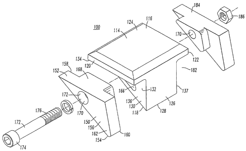
cutting and handling of
scrap. For example, in the dismantling of an industrial building, metal scrap,
in the form of
various diameter pipes, structural I-beains, channels, angles, sheet metal
plates and the like
must be efficiently severed and handled by heavy duty metal shears. Such
shears can also be
utilized for reducing automobiles, truck fraines, railroad cars and the like.
The shears must
be able to move and cut the metal scrap pieces regardless of the size or shape
of the
individual scrap pieces and without any significant damage to the shears. In
the demolition
of an industrial building, concrete crushing devices, such as a concrete
pulverizer or concrete
crackers, are also used to reduce the structure to manageable components which
can be easily
handled and removed from the site. Wood shears and plate shears also represent
specialized
cutting devices useful in particular deinolition or debris removal situations
depending on the
type of scrap. Also, a grapple is often utilized where handling of debris or
work pieces is a
primary function of the equipment. Historically, all of these pieces of
equipment represent
distinct tools having significant independent capital cost. Consequently, the
demolition
industry has tended to develop one type of tool that can be used for as many
of these
applications as possible.
[0003] For illustrative purposes, the following discussion will be directed to
metal shears.
One type of metal shear is a shear having a fixed blade and a movable blade
pivoted thereto.
The movable blade is pivoted by a hydraulic cylinder to provide a shearing
action between
CA 02563771 2008-07-10
the blades for severing the work pieces. Examples of this type of shears can
be found in prior
U. S. Patent Nos. 4,403,431; 4,670,983; 4,897,921; 5,926,958;and 5,940,971
which are
assigned to the assignee of this application.
[00041 Figure 1 illustrates a prior art, multiple tool attachment adapted to
be attached to
demolition or construction equipment, such as a backhoe (not shown). The
multiple tool
attachment is adapted to connect one of a series of tools or tool units to the
demolition
equipment. The tool attached in Figure 1 is a metal shear 10. The shear 10
includes a first
blade 12 connected to an upper jaw 13 and a second blade 14 connected to a
lower jaw 15,
wherein the jaws 13,15 are pivotally connected at a hub or main pin 16 to a
universal body
18. The body 18 is referred to as universal because it remains common to a
series of tools or
tool units in the attachment system. The universal body 18 is comprised of
sides 19, a
bearing housing 20 and a yoke 21.
[00051 The upper jaw 13 and the lower jaw 15 pivot about the main pin 16 to
form a
movable jaw assembly 22. At the end of the first blade 12 is a blade tip 24.
Details of the
blade tip 24 are provided in figures 3 and 4 wherein the blade tip 24 is
comprised of a base 26
having a top side 28, bottom side 30 and walls 32,34 therebetween. The base 26
of the blade
tip 24 is a completely solid piece and the top side 28 of the base 26 is
secured to a support 36
associated with the upper jaw 13.
[0006J Directing attention to figures 1 and 2 the second blade 14 has
associated with it a
guide channel 38 which accepts and provides lateral support to the blade tip
24 and the first
blade 12. To minimize the deflection experienced under load by the first blade
12 and the
blade tip 24, the tolerance for the guide channel 38 is fairly low.
[0007J In many applications, the first blade 12 and support 36 may be
laterally displaced
relative to the guide channel 38 such that upon entering the guide channel 38
the side of the
blade tip 24 experiences rubbing and extensive wear during normal operation.
This wear if
not properly maintained can lead to the first blade 12 becoming jammed or
stuck in the guide
channel 38. This condition is known as "stickers" in the industry. Stickers
can develop when
the clearance gap between the walls 32,34 of the tip 24 of the fnst blade 12
and the walls
40,42 of the guide channel 38 of the lower blade 14 become excessive enough to
allow
material to become wedged between these surfaces while shearing. Once the
first blade 12
becomes stuck within the guide channel 38, the shear 10 must oftentimes be
decommissioned
for repair. It is then necessary to build up the walls 32,34 of the tip 24 by
welding to keep
these gaps at a minimum. This process is very time consuming and costly and,
depending on
2
CA 02563771 2006-10-19
WO 2005/103395 PCT/US2005/012909
the material that the shear is processing, building up the tip could be
required as often as once
a week.
[0008] Therefore, a tip design is desired that may be easily repaired or
replaced when worn
to minimize the downtime of a shear or other equipment.
SUMMARY OF THE INVENTION
[0009] On embodiment of the subject invention is directed to a tip for
demolition and
construction equipment having a discrete base witli a top side, a bottom side
and walls
therebetween. The base also has a mounting surface on the top side of the base
adapted to be
secured to a support. The base furthermore has a central portion with a
cutting edge, whereby
the cutting edge is defined at the lowermost portion of the bottom side of the
base. A recess
extends into at least one wall of the base and the recess defines a recess
upper side, an inner
wall and a recess contour. An insert has a top side, a bottom side and walls
therebetween
with a cutting edge defined at the lowermost portion of the bottom side of the
insert and
generally aligned with the cutting edge of the base. The insert has a profile
which generally
conforms to the recess contour. An insert is secured within each recess.
[0010] Another embodiment of the subject invention is directed to the inserts
wllich are
secured within each base recess.
[0011] Yet another embodiment of the subject invention is directed to
demolition and
construction equipment utilizing such a tip.
[0012] Yet another embodiment of the subject invention is directed to a method
of securing
inserts within a tip for demolition and construction equipment comprising the
steps of
providing a common bore through the insert and the walls of the base at each
recess,
positioning an insert within each recess, inserting a fastener therethrough;
and securing the
fastener against each insert within the recess.
BRIEF DESCRIPTION OF THE DRAWINGS
[0013] Figure 1 is prior art and is a side view illustrating a inetal shear
incorporated into a
universal body for a construction tool system;
[0014] Figure 2 is prior art and is a plan view of the shear in Figure 1;
[0015] Figure 3 is prior art and is a front view of a blade tip;
[0016] Figure 4 is prior art and is a side view of the blade tip shown in
Figure 3;
[0017] Figure 5 is an enlarged portion of the encircled section in Figure 1,
however, with
the introduction of a blade tip in acoordance with the subject invention;
[0018] Figure 6 is an exploded perspective view of the tip illustrated in
Figure 5;
3
CA 02563771 2006-10-19
WO 2005/103395 PCT/US2005/012909
[0019] Figure 7 is an exploded section view of the blade tip wherein one
insert has a recess
to accept a nut;
[0020] Figure 8 is a side view of the base associated with the blade tip;
[0021] Figure 9 is a profile of the insert associated with the blade tip;
[0022] Figure 10 is a side view of one insert having an internally threaded
bore to accept a
bolt; and
[0023] Figure 11 is a perspective view of an alternate embodiment of an insert
which is
indexable in accordance with the subject invention.
DESCRIPTION OF THE PREFERRED EMBODIMENTS
[0024] For purposes of the description hereinafter, the terms "upper",
"lower", "right",
"left", "vertical", "horizontal", "top", "bottom" and derivatives thereof
shall relate to the
inventiori as it is oriented in the drawing figures. However, it is to be
understood that the
invention may assume various alternative variations and step sequences, except
where
expressly specified to the contrary. It is also to be understood that the
specific devices and
processes illustrated in the attached drawings, and described in the following
specification,
are simply exemplary embodiments of the invention. Hence, specific dimensions
and other
physical characteristics related to the embodiments disclosed herein are not
to be considered
as limiting.
[0025] Figure 5 illustrates a blade tip , 100 secured to a support 105 such as
the upper jaw
13 of a jaw assembly 22 used in an industrial shear. It should be appreciated
that although
this tip 100 will be discussed in the context of an industrial shear
associated with demolition
equipment, it should be appreciated that such a blade tip 100 can be
implemented on any type
of equipment that shears, cuts, cracks, crunches or processes any type of
material by motion
of the blade tip.
[0026] The blade tip 100 may be utilized, for example, as a shear tip, claw
tooth, crusher
tooth and any and all piercing/punching devices that currently exist or that
may be developed.
This tip has immediate applications for products such as shears, claws,
grapples, crushers,
crackers, rail breakers, multi-blade cutters, tree shears, ripper teeth,
grinding teeth, shearing
teeth and any mechanism that can utilize a disposable cutting part which is
subjected to wear.
[0027] Directing attention to Figures 6-9, the tip 100 is comprised of a
discrete base 114
having a top side 116, a bottom side 118 and walls 120, 122 therebetween. The
base 114 has
a mounting surface 124 on the top side 116 wherein the mounting surface 124 is
adapted to
be secured to the support 105 (Figure 5). The base 114 has a central portion
126 with a
cutting edge 128 whereby the cutting edge 128 is defined at the lowermost
portion 130 of the
4
CA 02563771 2006-10-19
WO 2005/103395 PCT/US2005/012909
bottom side 118 of the base 114. A recess 132 extends into at least one wall
120, 122 of the
base 114. The recess 132 defmes a recess upper side 134, a recess inner wall
136 and a
recess contour 138 (Figure 8). A second insert 184 will be described and is
secured within a
second recess 182.
[0028] Directing attention to insert 150, the insert 150 has a top side 152, a
bottom side
154 and walls 156, 158 therebetween. A cutting edge 160 is defined at the
lowermost portion
162 of the bottom side 154 of the insert 150 and is generally aligned with the
cutting edge
128 of the base 114.
[0029] Directing attention to Figures 8 and 9, the profile 164 of the insert
150 generally
conforms to the contour 138 of the recess 132. The recess contour 138 is
triangular and the
profile 164 of the tip 150 corresponds to this shape. The insert 150 is
secured within the
recess 132. Directing attention to Figure 7, when the insert 150 is secured
within the recess
132, the cutting edge 160 of the insert 150 is in approximate aligiunent with
the cutting edge
128 of the base 114. This is also true for insert 184 within the recess 182.
[0030] To provide additional support to the insert 150 within the recess 132,
the top side
152 of the insert 150 is positioned against the upper side 134 of the recess
132.
[0031] Redirecting attention to Figures 6 and 7, the base 114 further includes
a socket 166
extending into the inner wall 136 of the recess 132. The insert 150 further
includes a
projection 168 extending from the wall 158 wherein the projection 168 fits
within the socket
166 to support the insert 150 within the recess 132.
[0032] As illustrated in Figures 8 and 9, the socket 166 and the projection
168 have
matching shapes and are noncircular such that when the insert 150 is mounted
within the
recess 132 there is no relative rotation between the socket 166 and the
projection 168.
[0033] As illustrated in Figures 6 and 7, a common bore 170 extends through
the insert
150, the base 114 and the insert 184. A fastener 172 passes through the common
bore 170
and secures the inserts 150,184 within their respective recesses 132,182. The
fastener 172
may be a threaded bolt having a bolt head 174 and a threaded shaft 176. The
bore 170 may
include a counter bore 173 within the insert 150 to accept the bolt head 174
and, furthermore,
the bore 170 within the base 114 may have threads (not shown) to accept the
threaded shaft
176.
[0034] While so far only a single recess 132 and a single insert 150 have been
discussed in
detail, a second recess 182 is associated with the opposite wall 122 of the
base 114 and a
second insert 184 is secured within the recess 182 in the same fashion as the
insert 150 is
secured within the recess 132. When the fastener 172 has a bolt head 174 and a
threaded
CA 02563771 2006-10-19
WO 2005/103395 PCT/US2005/012909
shaft 176, the bore 170 of the insert 178 may have a countersink 178 to accept
the nut 186 to
engage the tlhreaded shaft 176 of the bolt 172.
[0035] In the alternative, an insert 190 having all of the features of insert
184 with the
exception of a countersunk portion of the bore to accept the nut 186 may
itself have a
threaded bore 185 to accept the threaded shaft 176 of the bolt 172, thereby
alleviating the
need for the nut 186 and the corresponding countersunk portion within the
insert 184 to
accommodate the nut 186.
[0036] Figure 11 illustrates a perspective view of an insert 200 having a top
side 216, a
bottom side 218 and an additional third side 220 with walls 222, 224
therebetween.
Extending from the wall 224 of the insert 200 is a projection 226 that is
centered about a bore
228 extending therethrough such that the projection 226 and the contour of the
first, second
and third sides 216, 218,220 are symmetric. As a result, with obvious
modifications to the
base 114 to accept the insert 200, the insert 200 may be indexable such that
multiple cutting
edges 230, 232, 234 may be positioned at the lowermost portion 130 of the
bottom side 118
of the base 114 and when one cutting edge becomes worn the insert 200 may be
rotated such
that a second cutting edge is exposed.
[0037] The invention is also directed to a method of securing an insert 150
within a tip 100
for demolition and construction equipment comprising the step of providing a
common bore
170 through the insert 150 and the walls 136, 137 of the base 114 at each
recess 132, 176.
Each insert 150, 178 is positioned witllin its respective recess 132, 176. A
fastener 172 is
inserted within the common bore 170 and the fastener 172 is then secured
against each insert
150, 178 within their respective recess 132, 176.
[0038] It should be appreciated that under most circumstances the only
maintenance for the
tip 100 will be the replacement of the inserts 150,184. However, it is
possible to remove the
base 114 from the support 36 to replace the entire tip 100 such that the tip
100 may be
considered to be disposable. Furthermore, depending upon the application for
which the tip
100 may be used, the material of the base 114 and the material of the tip 100
may be
different.
[0039] As a result of the tip 100 in accordance with the subject invention,
machine down
time and the associated expense may be significantly reduced. because worn
tips may be
quickly and easily replaced.
[0040] This invention has been described with reference to the preferred
embodiments.
Obvious modifications and alterations will occur to others upon reading and
understanding
6
CA 02563771 2006-10-19
WO 2005/103395 PCT/US2005/012909
the preceding detailed description. It is intended that the invention be
construed as including
all such modifications and alterations.
7