Sélection de la langue

Search

Sommaire du brevet 2566076 

Énoncé de désistement de responsabilité concernant l'information provenant de tiers

Une partie des informations de ce site Web a été fournie par des sources externes. Le gouvernement du Canada n'assume aucune responsabilité concernant la précision, l'actualité ou la fiabilité des informations fournies par les sources externes. Les utilisateurs qui désirent employer cette information devraient consulter directement la source des informations. Le contenu fourni par les sources externes n'est pas assujetti aux exigences sur les langues officielles, la protection des renseignements personnels et l'accessibilité.

Disponibilité de l'Abrégé et des Revendications

L'apparition de différences dans le texte et l'image des Revendications et de l'Abrégé dépend du moment auquel le document est publié. Les textes des Revendications et de l'Abrégé sont affichés :

  • lorsque la demande peut être examinée par le public;
  • lorsque le brevet est émis (délivrance).
(12) Brevet: (11) CA 2566076
(54) Titre français: PLAQUE DE SUSPENSION A FIXER A UN PLAFOND
(54) Titre anglais: SUSPENSION PLATE FOR FIXING TO CEILING
Statut: Réputé périmé
Données bibliographiques
(51) Classification internationale des brevets (CIB):
  • E04B 9/18 (2006.01)
(72) Inventeurs :
  • POURTIER, FABRICE (France)
  • RICORDI, CHRISTIAN (France)
(73) Titulaires :
  • SOCIETE DE PROSPECTION ET D'INVENTIONS TECHNIQUES SPIT (France)
(71) Demandeurs :
  • SOCIETE DE PROSPECTION ET D'INVENTIONS TECHNIQUES SPIT (France)
(74) Agent: FINLAYSON & SINGLEHURST
(74) Co-agent:
(45) Délivré: 2010-07-13
(86) Date de dépôt PCT: 2005-05-09
(87) Mise à la disponibilité du public: 2005-11-24
Requête d'examen: 2006-11-08
Licence disponible: S.O.
(25) Langue des documents déposés: Anglais

Traité de coopération en matière de brevets (PCT): Oui
(86) Numéro de la demande PCT: PCT/IB2005/001262
(87) Numéro de publication internationale PCT: WO2005/111334
(85) Entrée nationale: 2006-11-08

(30) Données de priorité de la demande:
Numéro de la demande Pays / territoire Date
0405139 France 2004-05-12

Abrégés

Abrégé français

La présente invention concerne une plaque de suspension qui est subdivisée en une pluralité de parties fonctionnelles (2, 13, 24) adjacentes comprenant une partie de fixation (2), lesdites parties étant séparées entre elles par une zone de pliure (10, 15) leur permettant d'être repliées par paires l'une par rapport à l'autre. L'une des zones de pliure (10) est fragilisée par au moins une encoche (11, 12) destinée à recevoir un ruban souple (25). L'invention s'applique en particulier à la suspension de faux plafonds.


Abrégé anglais


The suspension plate is divided into a plurality of adjacent functional
portions (2, 13, 24), including a fixing portion (2), the said portions each
being separated from another by a bending zone (10, 15) to be folded back in
pairs one towards the other. One of the bending zones (10) is weakened by at
least one notch (11, 12) for reception of a flexible strand (25). The
invention is applied, in particular, to the suspension of false ceilings.

Revendications

Note : Les revendications sont présentées dans la langue officielle dans laquelle elles ont été soumises.


7

Claims


1. Suspension plate for fixing to a ceiling, divided
into a plurality of adjacent functional portions (2, 13,
24), including a fixing portion (2), the said portions
each being separated from another by a bending zone (10,
15) to be foldable one towards the other two by two,
characterised by the fact that one of the bending zones
(10) is weakened by at least one notch (11, 12) for
reception of a flexible strand (25).

2. Suspension plate as described in claim 1, in which
the weakened and notched bending zone (10) includes two
notches (11, 12) at its two transversal,ends.

3. Plate as described in one of claims 1 and 2, in
which the weakened and notched bending zone (10)
separates the fixing portion (2) from an adjacent portion
(13).

4. Plate as described in one of claims 1 to 3, in which
at least three portions (2, 13, 24) are provided.

5. Plate as described in claim 4, in which four
portions (2, 13, 24, 35) are provided, arranged to form a
sleeve of rectangular section.

6. Plate as described in one of claims 1 to 5, in which
a part (24) is provided for reception of a threaded organ
(26).

Description

Note : Les descriptions sont présentées dans la langue officielle dans laquelle elles ont été soumises.


CA 02566076 2006-11-08
WO 2005/111334 PCT/IB2005/001262
Suspension plate for fixing to ceiling

The invention relates to suspension plates for fixing to
the ceiling of a room and to which can-be fixed or'from
which can be suspended in particular hooks or rods,
threaded or otherwise, and which will in turn-serve as
organs for suspension of another piece.

The devices to which this relates can be made from a flat
sheet-metal blank, cut-out and stamped, and divided into
a plurality of functional parts separated by bending
zones, a first part forming a fixing part, another part
being able to be a part for reception of a threaded rod
-or a bolt, and yet another part a part for reception of a
hook, etc..

Such a device is installed by firstly fixing the fixing
part of the suspension blank, then bending the blank so
that the part adjacent to the fixed part is folded back
and, often, comes substantially at right-angles to the
fixed part and so on, from blank part to adjacent blank
part.

The suspension plates are generally fixed to the ceiling
by means of a fixing apparatus of the gas, powder, or
pneumatic nailer type or other manually operated fixing
tool.

The bending (at right-angles) of the various parts of a
suspension blank, in pairs, along predetermined bending
zones determines its correct functioning. Now, the
suspension devices of the prior art give no fully
satisfactory guarantee in this respect. Moreover, the
devices of the prior art on not always of a sufficiently

CONFIRMATION COPY


CA 02566076 2006-11-08
WO 2005/111334 PCT/IB2005/001262
2

universal nature to allow fixing or hooking to them or
suspension from them under easy conditions of use, of all
the organs used by the -different trades encountered on
building or public works sites.
The present application is intended to meet these
requirements.

Thus, the invention relates to a suspension plate to be
-10' fixed to a ceiling, divided into a plurality of adjacent
functional portions, including a fixing portion, the said
portions.being separated each from another by a bending
zone to be folded one towards the other in pairs,
characterised by the fact that one of the bending zones
is weakened by'at least one notch for reception of a
flexible strand of a suspension element.

Flexible strand of a suspension element means principally
a strand of'a cable loop or other suspension wire for
20- example.for suspension of a false ceiling.

Naturally, two notches will be formed a priori at the two
transversal ends of the bending zone.

The invention is notable by the dual function of'the
notches, which are used not only to receive a cable or
other similar element, but also to weaken the bending
zone in question thus notched and therefore shortened,
with the advantageous result of ensuring that folding of
one of the two portions separated by this notched bending
zone towards the other, will indeed take place along this
bending zone and not to the side, for example along
another weakness such as a hole for reception of a hook.


CA 02566076 2006-11-08
WO 2005/111334 PCT/IB2005/001262
3

In the preferred embodiment of the suspension plate of
the invention, the notched bending zone separates the
fixing portion from an adjacent portion.

The invention will be better understood with the aid of
the following description of several embodiments of the
suspension.plate of the invention, with reference to the
attached drawings, in which

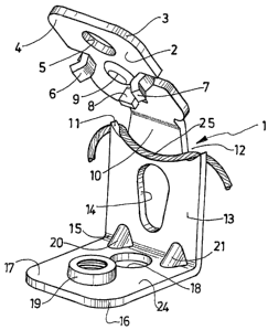
- figure 1 is a perspective view of a plate with three
portions with the portions more or less folded the.
ones towards the others;

- figure 2 is a side view slightly in pe'rspective of
the plate of figure.1, after folding back of the
portions the ories.relative to the others, with a
suspended cable and a bolt-fixed to the plate and
- figure 3 is a perspective view of-a plate with four
portions.completely folded back the ones relative-to
the others.
The suspension device which will now be described with
reference to figure 1 is here a rectangular plate 1 cut
out of a sheet-metal blank and formed of three parts,
each cut out and stamped as described hereinafter.
A first part 2 has firstly been cut out to form free
rounded corners 3, 4 and an orifice 5 for passage of a
fixing bolt and to free, before stamping, two lateral
tabs 6, 7 for centring and attachment to the nose (point-
guide) of the tool with which the plate will be fixed to
the ceiling, and a stop 8 and boss 9 also for fixing by
the tool. Then this plate part 2 has been stamped to form
the tabs 6, 7 and the stop 8 and a boss 9 for reception
of a fixing plug.


CA 02566076 2006-11-08
WO 2005/111334 PCT/IB2005/001262
4

A second part 13, adjacent to the fixing part 2, has also
been cut out to present-, in the junction zone 10 of the
two parts 2, 13, two lateral notches 11, 12, this zone 10
thus being shortened and therefore weakened. An oblong.
opening 14 has also been cut out at the centre of this
plate part 13, to receive the hook of a suspension rod,
for example.

-10 Lastly, the plate includes a third part 24, adjacent to
the part 13 along a zone 15. This plate part 24 has been
cut out to provide rounded free corners 16, 17 and an
orifice 18 for passage of a suspension rod, for example.
This plate part 24 has also been stamped to create a
small-passage 19 which has then been tapped to receive a'
threaded rod. Stop reinforcements 20, 21 have been
stamped in the zone 15. The junction zones 10, 15 of the plate parts in pairs
are-

20- bending.zones for folding back each of the plate parts
towards another.

In the example in question, the second and third parts
13, 24 of the original plate are already bent and folded
back one towards the.other at right-angles.

The use of the suspension plate will now be described.
The fixing part 2 is fixed to the ceiling of a room,
either by a plug fixed through the boss .9 or by means of
a pin anchored in the ceiling through the hole 5 and a
fixing organ of screw type. This fixing is advantageously
performed using a conventional fixing tool, the nose of


CA 02566076 2006-11-08
WO 2005/111334 PCT/IB2005/001262

which is slid between the tabs 6, 7 in the case of fixing
with a plug..

After fixing of this plate part 2 to the ceiling against
5 which it i.s therefore pressed flat, by means of a simple
tool, of the screwdriver type, or even with the hand, the
remainder of the plate is moved away, folding back the
plate part 13, here at right-angles to the part 2. This
folding back occurs naturally about the bending zone 10
weakened by the notches and not, for example, about a
zone passing through the orifice 14. The foldi.ng.back of
this part 13 occurs correctly, and it can come-to exactly
90 to the part 2.

15- The fact that the folding back,has been correctly
effected means that the third part of the plate 24 is
quite parallel with the second part 2 and therefore with
the ceiling.

The suspension device-l being fixed and conformed in the
use position, it is possible either to pass a cable loop
around the zone 10 of junction of the two plate parts
2, 13, in the notches 11, 12, or to introduce a. hooked
rod into the holes 18, 14, or to screw a bolt 26 or a
25 threaded rod into the tapped orifice 19 of the plate part
24.

The second embodiment 31 of the suspension plate of the
invention shown in.Figure 3 includes no longer three, but
four parts intended to form a sleeve of rectangular
section. It is only distinguished by the fourth part 35
only intended to strengthen the suspension device and to
firmly attach the first and third plate parts and to
ensure perfect 90 folds. The means of figure 3 identical


CA 02566076 2006-11-08
WO 2005/111334 PCT/IB2005/001262
6

to those of figure 1 carry the same reference marks. The
two plate parts 2 and 35.are joined together by a bending
zone 36.

Dessin représentatif
Une figure unique qui représente un dessin illustrant l'invention.
États administratifs

Pour une meilleure compréhension de l'état de la demande ou brevet qui figure sur cette page, la rubrique Mise en garde , et les descriptions de Brevet , États administratifs , Taxes périodiques et Historique des paiements devraient être consultées.

États administratifs

Titre Date
Date de délivrance prévu 2010-07-13
(86) Date de dépôt PCT 2005-05-09
(87) Date de publication PCT 2005-11-24
(85) Entrée nationale 2006-11-08
Requête d'examen 2006-11-08
(45) Délivré 2010-07-13
Réputé périmé 2013-05-09

Historique d'abandonnement

Il n'y a pas d'historique d'abandonnement

Historique des paiements

Type de taxes Anniversaire Échéance Montant payé Date payée
Requête d'examen 800,00 $ 2006-11-08
Le dépôt d'une demande de brevet 400,00 $ 2006-11-08
Enregistrement de documents 100,00 $ 2007-04-11
Taxe de maintien en état - Demande - nouvelle loi 2 2007-05-09 100,00 $ 2007-04-18
Taxe de maintien en état - Demande - nouvelle loi 3 2008-05-09 100,00 $ 2008-04-21
Taxe de maintien en état - Demande - nouvelle loi 4 2009-05-11 100,00 $ 2009-04-23
Taxe finale 300,00 $ 2010-04-08
Taxe de maintien en état - Demande - nouvelle loi 5 2010-05-10 200,00 $ 2010-04-20
Taxe de maintien en état - brevet - nouvelle loi 6 2011-05-09 200,00 $ 2011-04-18
Titulaires au dossier

Les titulaires actuels et antérieures au dossier sont affichés en ordre alphabétique.

Titulaires actuels au dossier
SOCIETE DE PROSPECTION ET D'INVENTIONS TECHNIQUES SPIT
Titulaires antérieures au dossier
POURTIER, FABRICE
RICORDI, CHRISTIAN
Les propriétaires antérieurs qui ne figurent pas dans la liste des « Propriétaires au dossier » apparaîtront dans d'autres documents au dossier.
Documents

Pour visionner les fichiers sélectionnés, entrer le code reCAPTCHA :


Pour visualiser une image, cliquer sur un lien dans la colonne description du document. Pour télécharger l'image (les images), cliquer l'une ou plusieurs cases à cocher dans la première colonne et ensuite cliquer sur le bouton "Télécharger sélection en format PDF (archive Zip)" ou le bouton "Télécharger sélection (en un fichier PDF fusionné)".

Liste des documents de brevet publiés et non publiés sur la BDBC .

Si vous avez des difficultés à accéder au contenu, veuillez communiquer avec le Centre de services à la clientèle au 1-866-997-1936, ou envoyer un courriel au Centre de service à la clientèle de l'OPIC.


Description du
Document 
Date
(yyyy-mm-dd) 
Nombre de pages   Taille de l'image (Ko) 
Dessins représentatifs 2007-01-15 1 12
Page couverture 2007-01-16 1 42
Abrégé 2006-11-08 2 102
Revendications 2006-11-08 1 32
Dessins 2006-11-08 2 58
Description 2006-11-08 6 214
Revendications 2009-01-19 1 28
Revendications 2009-10-06 2 55
Description 2009-10-06 7 229
Page couverture 2010-06-23 1 42
Correspondance 2007-01-11 1 27
PCT 2006-11-08 6 196
Cession 2006-11-08 4 112
Cession 2007-04-11 5 158
Poursuite-Amendment 2008-08-12 2 51
Poursuite-Amendment 2009-01-19 4 97
Poursuite-Amendment 2009-04-07 3 83
Correspondance 2010-04-08 1 37
Poursuite-Amendment 2009-10-06 7 180