Sélection de la langue

Search

Sommaire du brevet 2567842 

Énoncé de désistement de responsabilité concernant l'information provenant de tiers

Une partie des informations de ce site Web a été fournie par des sources externes. Le gouvernement du Canada n'assume aucune responsabilité concernant la précision, l'actualité ou la fiabilité des informations fournies par les sources externes. Les utilisateurs qui désirent employer cette information devraient consulter directement la source des informations. Le contenu fourni par les sources externes n'est pas assujetti aux exigences sur les langues officielles, la protection des renseignements personnels et l'accessibilité.

Disponibilité de l'Abrégé et des Revendications

L'apparition de différences dans le texte et l'image des Revendications et de l'Abrégé dépend du moment auquel le document est publié. Les textes des Revendications et de l'Abrégé sont affichés :

  • lorsque la demande peut être examinée par le public;
  • lorsque le brevet est émis (délivrance).
(12) Brevet: (11) CA 2567842
(54) Titre français: PROCEDE ET DISPOSITIF DE GONFLAGE D'UN CORPS SOUMIS A UNE SURPRESSION
(54) Titre anglais: A METHOD AND A DEVICE FOR EXPANDING A BODY UNDER OVERPRESSURE
Statut: Réputé périmé
Données bibliographiques
(51) Classification internationale des brevets (CIB):
  • E21B 33/12 (2006.01)
  • E21B 43/12 (2006.01)
(72) Inventeurs :
  • FREYER, RUNE (Norvège)
(73) Titulaires :
  • EASY WELL SOLUTIONS AS (Norvège)
(71) Demandeurs :
  • EASY WELL SOLUTIONS AS (Norvège)
(74) Agent: NORTON ROSE FULBRIGHT CANADA LLP/S.E.N.C.R.L., S.R.L.
(74) Co-agent:
(45) Délivré: 2009-10-20
(86) Date de dépôt PCT: 2005-05-23
(87) Mise à la disponibilité du public: 2005-12-08
Requête d'examen: 2007-03-19
Licence disponible: S.O.
(25) Langue des documents déposés: Anglais

Traité de coopération en matière de brevets (PCT): Oui
(86) Numéro de la demande PCT: PCT/NO2005/000170
(87) Numéro de publication internationale PCT: WO2005/116394
(85) Entrée nationale: 2006-11-23

(30) Données de priorité de la demande:
Numéro de la demande Pays / territoire Date
20042134 Norvège 2004-05-25

Abrégés

Abrégé français

L'invention concerne un procédé et un dispositif de gonflage d'un corps (10, 22) soumis à une surpression. Le corps (10, 22), qui est constitué d'un matériau (12, 24) dont une partie considérable est percée de cavités, et est comprimé lorsqu'il est placé dans une zone de surpression, est gonflé par le remplissage des cavités avec un liquide.


Abrégé anglais


A method and a device for expanding a body (10, 22) under overpressure, in
which the body (10, 22) which is formed of a material (12, 24) with a
considerable portion of cavities, and which is compressed when being placed in
an area of overpressure, is expanded by the cavities filling with fluid.

Revendications

Note : Les revendications sont présentées dans la langue officielle dans laquelle elles ont été soumises.


6
CLAIMS:

1. A method for expanding a body under elevated pressure, the method
comprising the steps of:
forming a body from an elastic material with a substantial portion of cavities

therein;
placing the body in an area of elevated pressure; and
expanding the body by diffusion of a fluid through the elastic material and
into
the cavities.

2. The method of Claim 1, wherein the body is compressed by the elevated
pressure during the placing step.

3. The method of Claim 1, wherein the cavities are compressed by the elevated
pressure during the placing step.

4. The method of Claim 1, wherein the cavities are expanded by diffusion of
the
fluid through the elastic material and into the cavities during the expanding
step.

5. The method of Claim 1, wherein the body is compressed by a preloading
material before the placing step.

6. A device for expanding a body under elevated pressure, the device
comprising:
the body being formed of an elastic material with a substantial portion of
cavities therein, wherein the body is compressed and then expanded by
diffusion of a fluid
through the elastic material and into the cavities.

7. A method of sealing in a well, the method comprising the steps of:
positioning an expandable body in the well, the body including a material
having cavities therein, the positioning step including applying an elevated
pressure to the
body;


7
compressing the body, thereby reducing a volume of the body, as a result of
the elevated pressure; and
then expanding the body into sealing contact with a surface in the wall.

8. The method of Claim 7, wherein the compressing step further comprises
reducing a volume of the cavities.

9. The method of Claim 7, wherein the expanding step further comprises
increasing a volume of the cavities.

10. The method of Claim 7, wherein the expanding step further comprises
diffusing a fluid through the material surrounding the cavities, whereby the
fluid enters the
cavities through the material.

11. The method of Claim 7, wherein the cavities comprise closed cavities.

12. The method of Claim 7, wherein the material comprises an elastic
diffusible
material.

Description

Note : Les descriptions sont présentées dans la langue officielle dans laquelle elles ont été soumises.


CA 02567842 2006-11-23
WO 2005/116394 PCT/N02005/000170
1
A METHOD AND A DEVICE FOR EXPANDING A BODY UNDER OVERPRESSURE
This invention relates to a method for expanding a body under
overpressure. More particularly, it concerns the expansion of
a body that is made of an elastic material having a
considerable portion of closed cavities, the material
allowing the diffusion of a fluid through the material and
into the cavities. The method is particularly suitable for
operations in the ground, in which a body of this kind, when
it is being lowered to the desired position, is compressed by
3.0 the prevailing overpressure, after which a fluid diffuses,
over some time, through the material and into the cavities.
Alternatively, the cavities are open and are held in
compression during insertion into an area of elevated
pressure. The invention also includes a device for practicing
3.5 the method.

Bodies of this kind may have a number of applications, for
example as an annular packer in an underground well. In this
description, to illustrate the operation, such an application
has been taken as the starting-point. The example does not in
20 any way limit the use of the body to this example.


CA 02567842 2009-01-13
2

Completing a petroleum well by means of a sand screen in an open hole is a
simple and
reliable method for completing a reservoir section. A petroleum well normally
penetrates
formations of varying production properties. These different properties may
lead to undesired
well fluid of an area flowing in through the sand screen and further into the
production pipe.

It may thus be desirable to close off an area to the inflow of fluid. This
closing off must take
place in the annulus between the sand screen and the well hole.

According to the prior art, such closing off is effected for example by means
of inflatable
annular packers which are placed at a desirable location, and which are then
activated by
means of relatively complicated equipment. It has sometimes turned out to be
difficult to
achieve pressure tightness by the use of packers of this kind.

NO Patent 312478 discloses a packer which is made of a swellable material.
After the packer
has been placed at a desired location, the material of the packer absorbs a
fluid and thereby
swells until it seals the annulus. In some wells, for example when dry gas is
produced, it can
be difficult to achieve sufficient swelling of the packer material.

The invention has as its object to remedy the drawbacks of the prior art.


CA 02567842 2009-01-13
3

In accordance with another aspect, there is provided a method for expanding a
body under
elevated pressure, the method comprising the steps of: forming a body from an
elastic
material with a substantial portion of cavities therein; placing the body in
an area of elevated
pressure; and expanding the body by diffusion of a fluid through the elastic
material and into
the cavities.

By placing a body which is made of an elastic material with a considerable
portion of closed
cavities, the material allowing the diffusion. of a fluid through the material
into the cavities, in
an area where overpressure is prevailing, the material will be compressed, in
particular
through reduction of the volume of the cavities and thereby that of the
material.

Over time a surrounding fluid diffuses through the material into the cavities,
whereby the
body expands into its essentially original dimension, possibly until it is
prevented from
further expansion by adjacent bodies.

Alternatively, the elastic material may be formed with many open cavities, the
material being
kept in compression, for example by means of a compressing material, so that
the cavities are
at least partially compressed during insertion of the material into an area of
elevated pressure.
After the material has been placed in the area in question, the material is
released from its
compressed state, whereby fluid flows into the cavities of the material. The
material thereby
expands to its essentially original size.

Bodies of this kind are suitable for application also in water wells and dry
gas wells, in which
swelling materials are usable only to a limited degree.

In what follows is described a non-limiting example of a preferred method and
embodiment
which are visualized in the accompanying drawings, in which:

Figure 1 shows a production pipe with a sand screen in an underground well, in
which there
are arranged annular packers


CA 02567842 2006-11-23
WO 2005/116394 PCT/N02005/000170
4
according to the invention to limit the admission area of the
sand screen;

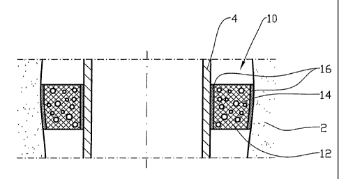
Figure 2 shows, on a larger scale, a section of Figure 1;
Figure 3 shows an expandable pipe which is provided
s externally with a sleeve of compressed expandable material
before expansion has taken place; and

Figure 4 shows the same pipe as Figure 3 after the expansion
of the expandable pipe and material has taken place.

In the drawings the reference numeral 1 identifies an
underground well in a reservoir formation 2. A production
pipe 4 including a sand screen 6 is placed in the underground
well 1. Well fluid, indicated in Figure 1 by arrows 8, flows
from the reservoir formation 2 into the production pipe 4
through the sand screen G. The underground well 1 forms an
area of overpressure due to the height of the fluid column of
the well.

In order to shut off the inflow of fluid into the production
pipe 4 from adjacent areas, annular packers 10 have been set.
The annular packers 10, see Figure 2, are made of an elastic
material 12 with a considerable portion of closed cavities
14, the material allowing'the diffusion of a fluid through
the material 12 into the cavities 14. The material 12 may be
nitrile rubber, for example. The material 12 may be provided
with one or more reinforcements 16, for example in the form
of fibre cloth.

The annular packer 10 is formed with a somewhat larger
transverse dimension than the transverse dimension of the


CA 02567842 2006-11-23
WO 2005/116394 PCT/N02005/000170
opening which it is to fill. When the annular packer 10 is
run into the underground well 1, the cavities 14 of the
material are compressed due to an increasing static pressure.
Thereby, the annular packer 10 can easily be moved forward
s into the desired position.

The diffusion of fluid through the material 12 into the
cavities 14 of the material 12 will start immediately. The
cavities 14 are thereby filled, so that the pressure within
the cavities 14 will be approximately equal to the prevailing
pressure at the annular packer 10. Thereby, the annular
packer 10 will attempt to adopt its original shape. If the
diameter of the underground well is smaller than the original
diameter of the annular packer 10, the annular packer 10 will
tighten against the formation wall 18 of the underground well
is 1, alternatively against a casing, not shown, if the
underground well 1 is cased.

In an alternative embodiment, see Figures 3 and 4, an
expandable pipe 20 is provided with an encircling sleeve 22
of a material 24 which has open pore-like cavities. Before
insertion into the underground well 1, the material 24 of the
sleeve 22 is compressed by means of an encircling preloading
material 26. The preloading material 26 may be formed by, for
example, a fibre cloth.

After the expandable pipe 20 has been placed in a desired
position, the expandable pipe 20 is expanded, whereby the
preloading material 26 bursts.

The expansion of the sleeve 22 then takes place by fluid
flowing into the cavities of the material 24, whereby the
sleeve 22 is expanded into its original shape.


Dessin représentatif
Une figure unique qui représente un dessin illustrant l'invention.
États administratifs

Pour une meilleure compréhension de l'état de la demande ou brevet qui figure sur cette page, la rubrique Mise en garde , et les descriptions de Brevet , États administratifs , Taxes périodiques et Historique des paiements devraient être consultées.

États administratifs

Titre Date
Date de délivrance prévu 2009-10-20
(86) Date de dépôt PCT 2005-05-23
(87) Date de publication PCT 2005-12-08
(85) Entrée nationale 2006-11-23
Requête d'examen 2007-03-19
(45) Délivré 2009-10-20
Réputé périmé 2015-05-25

Historique d'abandonnement

Il n'y a pas d'historique d'abandonnement

Historique des paiements

Type de taxes Anniversaire Échéance Montant payé Date payée
Enregistrement de documents 100,00 $ 2006-11-23
Le dépôt d'une demande de brevet 400,00 $ 2006-11-23
Requête d'examen 800,00 $ 2007-03-19
Taxe de maintien en état - Demande - nouvelle loi 2 2007-05-23 100,00 $ 2007-05-22
Taxe de maintien en état - Demande - nouvelle loi 3 2008-05-23 100,00 $ 2008-04-09
Taxe de maintien en état - Demande - nouvelle loi 4 2009-05-25 100,00 $ 2009-04-20
Taxe finale 300,00 $ 2009-07-30
Taxe de maintien en état - brevet - nouvelle loi 5 2010-05-25 200,00 $ 2010-04-07
Taxe de maintien en état - brevet - nouvelle loi 6 2011-05-23 200,00 $ 2011-04-18
Taxe de maintien en état - brevet - nouvelle loi 7 2012-05-23 200,00 $ 2012-04-16
Taxe de maintien en état - brevet - nouvelle loi 8 2013-05-23 200,00 $ 2013-04-15
Titulaires au dossier

Les titulaires actuels et antérieures au dossier sont affichés en ordre alphabétique.

Titulaires actuels au dossier
EASY WELL SOLUTIONS AS
Titulaires antérieures au dossier
FREYER, RUNE
Les propriétaires antérieurs qui ne figurent pas dans la liste des « Propriétaires au dossier » apparaîtront dans d'autres documents au dossier.
Documents

Pour visionner les fichiers sélectionnés, entrer le code reCAPTCHA :


Pour visualiser une image, cliquer sur un lien dans la colonne description du document. Pour télécharger l'image (les images), cliquer l'une ou plusieurs cases à cocher dans la première colonne et ensuite cliquer sur le bouton "Télécharger sélection en format PDF (archive Zip)" ou le bouton "Télécharger sélection (en un fichier PDF fusionné)".

Liste des documents de brevet publiés et non publiés sur la BDBC .

Si vous avez des difficultés à accéder au contenu, veuillez communiquer avec le Centre de services à la clientèle au 1-866-997-1936, ou envoyer un courriel au Centre de service à la clientèle de l'OPIC.


Description du
Document 
Date
(yyyy-mm-dd) 
Nombre de pages   Taille de l'image (Ko) 
Revendications 2006-11-23 1 36
Abrégé 2006-11-23 1 55
Dessins 2006-11-23 3 52
Description 2006-11-23 5 205
Dessins représentatifs 2006-11-23 1 10
Page couverture 2007-01-29 1 37
Revendications 2009-01-13 2 48
Description 2009-01-13 5 190
Dessins représentatifs 2009-09-24 1 11
Page couverture 2009-09-24 1 39
Correspondance 2007-05-02 1 13
Correspondance 2007-05-02 1 16
Poursuite-Amendment 2007-05-07 1 18
Poursuite-Amendment 2007-05-07 1 14
Correspondance 2007-01-22 1 49
PCT 2006-11-23 9 354
Cession 2006-11-23 5 113
Poursuite-Amendment 2007-03-19 1 28
Correspondance 2007-04-25 2 67
Poursuite-Amendment 2008-07-14 2 69
Poursuite-Amendment 2009-01-13 7 228
Correspondance 2009-07-30 2 67