Sélection de la langue

Search

Sommaire du brevet 2573076 

Énoncé de désistement de responsabilité concernant l'information provenant de tiers

Une partie des informations de ce site Web a été fournie par des sources externes. Le gouvernement du Canada n'assume aucune responsabilité concernant la précision, l'actualité ou la fiabilité des informations fournies par les sources externes. Les utilisateurs qui désirent employer cette information devraient consulter directement la source des informations. Le contenu fourni par les sources externes n'est pas assujetti aux exigences sur les langues officielles, la protection des renseignements personnels et l'accessibilité.

Disponibilité de l'Abrégé et des Revendications

L'apparition de différences dans le texte et l'image des Revendications et de l'Abrégé dépend du moment auquel le document est publié. Les textes des Revendications et de l'Abrégé sont affichés :

  • lorsque la demande peut être examinée par le public;
  • lorsque le brevet est émis (délivrance).
(12) Brevet: (11) CA 2573076
(54) Titre français: AGENCEMENT DE REFROIDISSEMENT POUR UNE BOITE D'ENGRENAGES ACCESSOIRE ET PROCEDE DE REFROIDISSEMENT
(54) Titre anglais: COOLING ARRANGEMENT FOR AN ACCESSORY GEARBOX AND METHOD OF COOLING
Statut: Réputé périmé
Données bibliographiques
(51) Classification internationale des brevets (CIB):
  • F02C 7/12 (2006.01)
  • F02C 7/32 (2006.01)
  • F02C 7/36 (2006.01)
  • F16H 57/04 (2010.01)
(72) Inventeurs :
  • BROUILLET, DAVID (Canada)
(73) Titulaires :
  • PRATT & WHITNEY CANADA CORP. (Canada)
(71) Demandeurs :
  • PRATT & WHITNEY CANADA CORP. (Canada)
(74) Agent: NORTON ROSE FULBRIGHT CANADA LLP/S.E.N.C.R.L., S.R.L.
(74) Co-agent:
(45) Délivré: 2014-09-02
(86) Date de dépôt PCT: 2005-07-06
(87) Mise à la disponibilité du public: 2006-01-19
Requête d'examen: 2010-06-14
Licence disponible: S.O.
(25) Langue des documents déposés: Anglais

Traité de coopération en matière de brevets (PCT): Oui
(86) Numéro de la demande PCT: PCT/CA2005/001053
(87) Numéro de publication internationale PCT: WO2006/005162
(85) Entrée nationale: 2007-01-08

(30) Données de priorité de la demande:
Numéro de la demande Pays / territoire Date
10/886,603 Etats-Unis d'Amérique 2004-07-09

Abrégés

Abrégé français

Boîtier ou boîte renfermant l'engrenage utilisé pour transmettre la puissance à différents accessoires (AGB) (30) mise en marche par une turbine à gaz nécessitant le refroidissement. Refroidissement de l'accessoire (20) de manière externe sans nécessité de caloporteur s'écoulant dans l'accessoire (20). Ceci est réalisé par l'utilisation d'une boîte d'engrenages accessoire (AGB) (30) à titre de limite externe d'une chemise de refroidissement cylindrique, la limite interne se trouvant sur ou dans la surface externe de l'accessoire. Un caloporteur s'écoule par la suite depuis une entrée sur l'AGB (30) à travers la chemise de refroidissement vers une sortie sur l'AGB (30). Le caloporteur peut alors être envoyé vers d'autres échangeurs thermiques ou éléments du système. Ceci rend inutile les passages internes de caloporteur/lubrifiant dans l'accessoire (20).


Abrégé anglais


The housing or box enclosing the gearing which is used to transmit power to
various accessories (AGB) (30) serviced
by a gas turbine requires cooling. The invention provides cooling to the
accessory (20) externally without the need for any coolant
flow inside the accessory (20). This is done by using the accessory gearbox
(AGB) (30) as the outer boundary of a cylindrical cooling
jacket with the inner boundary being on or in the exterior surface of the
accessory. A coolant then flows from an inlet on the AGB
(30) through the cooling jacket, to an outlet on the AGB (30). The coolant may
then be sent to other heat exchangers or elements of
the system. This eliminates the need for internal coolant/lubrication passages
in the accessory (20).

Revendications

Note : Les revendications sont présentées dans la langue officielle dans laquelle elles ont été soumises.


- 6 -
CLAIMED:
1. A cooling system for accessory gearbox (AGB) of a gas turbine
engine, the AGB having an internal wall surface defining a
housing in which is located an accessory having an external
side surface radially inward of the internal wall, the
cooling system comprising:
at least one coolant fluid passage located between the internal
wall surface of the AGB and the external side surface of
the accessory, the passage extending from at least one
inlet to at least one outlet, the inlet and outlet being in
fluid communication with a coolant fluid circuit, the
coolant fluid being oil and the coolant fluid circuit
including a main oil circuit communicating with at least
one main bearing cavity in the engine.
2. The cooling system according to claim 1, wherein the
accessory and the housing have a circular cross section.
3. The cooling system according to claim 1, wherein the internal
wall surface of the AGB and the external side surface of
the accessory define the coolant fluid passage.
4. The cooling system according to claim 1, wherein the fluid
directly contacts the external side surface of the
accessory to thereby cool the accessory.
5. The cooling system according to claim 1, wherein the
accessory is substantially enveloped by the internal wall
surface of the AGB.
6. A cooling system for accessory gearbox (AGB) of a gas turbine
engine, the AGB having an internal wall surface defining a
housing in which is located an accessory having an external
side surface radially inward of the internal wall, the
cooling system comprising: at least one coolant fluid
passage located between the internal wall surface of the

- 7 -
AGB and the external side surface of the accessory, the
passage extending from at least one inlet to at least one
outlet, the inlet and outlet being in fluid communication
with a coolant fluid circuit, the accessory being sealingly
received by the internal wall surface of the AGB.
7. The cooling system according to claim 6, wherein the fluid is
a liquid coolant.
8. The cooling system according to claim 6, wherein the internal
wall surface of the AGB and the external side surface of
the accessory define the coolant fluid passage.
9. The cooling system according to claim 6, wherein the coolant
fluid directly contacts the external side surface of the
accessory to thereby cool the accessory.
10. The cooling system according to claim 6, wherein the
accessory is substantially enveloped by the internal wall
surface of the AGB.
11. A cooling system for accessory gearbox (AGB) of a gas
turbine engine, the AGB having an internal wall surface
defining a housing in which is located an accessory having
an external side surface radially inward of the internal
wall, the cooling system comprising:
at least one coolant fluid passage located between the internal
wall surface of the AGB and the external side surface of
the accessory, the passage extending from at least one
inlet to at least one outlet, the inlet and outlet being in
fluid communication with a coolant fluid circuit, wherein
the coolant fluid passage is at least partially axially
delimited by a pair of spaced-apart seals extending between
the internal wall surface of the AGB and the external side
surface of the accessory.


- 8 -
12. The cooling system according to claim 11, wherein the
accessory and the housing have a circular cross section.
13. The cooling system according to claim 11, wherein the
internal wall surface of the AGB and the external side
surface of the accessory define the coolant fluid passage.
14. The cooling system according to claim 13, wherein the
coolant fluid directly contacts the external side surface
of the accessory to thereby cool the accessory.
15. The cooling system according to claim 11, wherein the
coolant fluid is oil and the coolant fluid circuit is
includes a main oil circuit communicating with at least one
main bearing cavity in the engine.
16. The cooling system according to claim 11, wherein the
accessory is substantially enveloped by the internal wall
surface of the AGB.
17. The cooling system according to claim 11, wherein the
accessory is sealingly received by the internal wall
surface of the AGB.

Description

Note : Les descriptions sont présentées dans la langue officielle dans laquelle elles ont été soumises.

CA 02573076 2007-01-08
WO 2006/005162 PCT/CA2005/001053
- 1 -
COOLING ARRANGEMENT FOR AN ACCESSORY GEARBOX
AND METHOD OF COOLING
TECHNICAL FIELD
The technical field of the invention relates generally to
cooling arrangements and methods of cooling, more
particularly to a cooling arrangement for an accessory
used in an accessory gearbox of a gas turbine engine and
a method of cooling the accessory.
BACKGROUND
Typically, gas turbine engines are equipped with various
mechanically-driven accessories which are connected tto a
casing referred to an accessory gearbox (AGB).
Some accessories are generating intense heat during their
operation and for this reason, they require cooling.
Typically, oil in the AGB is used for cooling the
accessories, particularly the starter/generator unit.
Oil passages are provided inside the starter/generator
unit and heat is exchanged between the oil and the
internal parts of the starter/generator unit.
This
arrangement has been used in the past in an extensive
number of designs. However, it requires oil connectors
between the AGB and the electrical device, and also
internal oil passages in the electrical device.
SUMMARY
A first aspect of the present invention relates to a
cooling system for accessory gearbox (AGB) of a gas
turbine engine, the AGB having an internal wall surface
defining a housing in which is located an accessory

CA 02573076 2007-01-08
WO 2006/005162 PCT/CA2005/001053
- 2 -
having an external side surface radially inward of the
internal wall, the cooling system comprising:
at least one coolant fluid passage located between
the internal wall surface of the AGB and the external =
side surface of the accessory, the passage extending from
at least one inlet to at least one outlet, the inlet and
outlet being in fluid communication with a coolant fluid
circuit.
Another aspect of the present invention relates to a
ip method of cooling a gas turbine accessory comprising the
steps of:
circulating engine oil from an engine oil circuit
around the outside of the accessory, and
circulating the oil within the engine to provide at
least one of cooling and lubrication to at least one
other part of the engine.
Still other features and advantages of the present
invention will be better understood with reference to the
preferred embodiments described hereinafter.
DESCRIPTION OF THE DRAWINGS
Fig. 1 schematically shows a generic gas turbine engine
to illustrate an example of a general environment in
which is located an accessory gearbox.
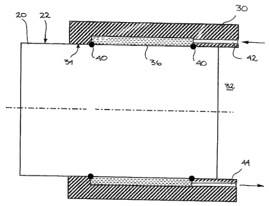
Fig. 2 is a schematic cross-sectional view of an
accessory located in a housing of an accessory gearbox
incorporating the new arrangement.
Fig. 3. is a view similar to Fig. 2, showing a variant of
the new arrangement.

CA 02573076 2007-01-08
WO 2006/005162 PCT/CA2005/001053
- 3 -
Fig. 4 is a view similar to Figs. 2 and 3, showing
another variant of the new arrangement.
Fig. 5 is a block diagram illustrating an example of a
coiling 6 1 path of a gas turbine engine.
DETAILED DESCRIPTION
Fig. 1 illustrates an example of a gas turbine engine 10
of a type preferably provided for use in subsonic flight,
generally comprising in serial flow communication a fan
12 through which ambient air is propelled, a multistage
compressor 14 for pressurizing the air, a combustor 16 in
which the compressed air is mixed with fuel and ignited
for generating an annular stream of hot combustion gases,
and a turbine section 18 for extracting energy from the
combustion gases.
Fig. 2 schematically illustrates an accessory or other
gas turbine-mounted device 20, such as a starter,
generator or starter-generator unit, which is secured
into an accessory gearbox (AGB) 30. The accessory 20 is
partially embedded within a housing 32 of the AGB 30,
thus having a significant amount, and preferably more
than half, of its volume within the housing 32. The
housing 32 of the AGB 30 is generally internally defined
by an internal wall surface 34. This
internal wall
surface 34 is preferably shaped and configured to
sealingly receive the external side surface 22 of the
accessory 20.
An annular oil passage 36 is provided between the
internal wall surface 34 of the AGB 30 and the external
side wall surface 22 of the accessory 20. The embodiment
illustrated in Fig. 2 shows the passage 36 being located

CA 02573076 2007-01-08
WO 2006/005162 PCT/CA2005/001053
- 4 -
in the internal wall surface 34 of the AGB 30. As shown
in Fig. 3, passage 36 can also be defined in the external
side surface 22 of the accessory 20, or passage 36 can
also be defined by recesses in a combination of both
surface 34 and surface 22, as shown in Fig. 4, or simply
by any internal space defined within the AGB and
preferably immediately adjacent surface 34. Opposite o-
ring seals 40 are provided at both ends to ensure
sealing.
As can be appreciated, the arrangement described herein
creates a cooling jacket around the accessory 20 and
allows heat to be exchanged, which may negate the need
for additional cooling means, such as internal oil
passages inside the accessory 20.
Oil is provided by the gas turbine's oil system (not
depicted in this Figure) to the annular oil passage 36
from at least one inlet oil passage 42, preferably
located in the internal wall surface 34 of the AGB 30.
Similarly, oil exits the annular oil passage 36 through
at least one outlet oil passage 44 located in the
internal wall surface 34 of the AGB 30, for return to the
oil system. These inlet and outlet oil passages 42,44
are preferably configured and disposed to generate a
constant flow of oil in the various regions of the
annular oil passage 36. - The flow is preferably
sufficient to provide the desired cooling =to accessory
20.
Fig. 5 schematically illustrates an overall example of an
example oil circuit of a gas turbine engine 10. Oil is
pumped from a tank 50 and sent to a filter unit 52. A
heat exchanger 54 cools the oil. At least some of the

CA 02573076 2007-01-08
WO 2006/005162 PCT/CA2005/001053
- 5 -
oil is then provided to the accessory 20 for cooling
thereof, preferably as described above. The oil then
circulates to the bearing cavities of the engine 10,
particularly in the various bearings therein. Oil
is
then supplied to the AGB 30 before being returned to the
tank 50.
The above description is meant to be exemplary only, and
one skilled in the art will recognize that changes may be
made without departing from the scope of the invention
disclosed. For
example, the present invention is not
limited to a single annular oil passage 36. Two or more
oil passages can be used. and may communicate in parallel
or serially with the source. The shape of the annular
oil passage 36 may be any desirable and is not
necessarily with a purely circular path but can include
spiral-shaped paths and/or other cooling-enhancing
features such as trip strips, etc. Although oil is the
preferred coolant with which the invention is used, any
suitable cooling fluids may be used.
Still other
modifications will be apparent to those skilled in the
art, in light of a review of the present disclosure, and
such modifications are intended to fall within the scope
of the appended claims.

Dessin représentatif
Une figure unique qui représente un dessin illustrant l'invention.
États administratifs

Pour une meilleure compréhension de l'état de la demande ou brevet qui figure sur cette page, la rubrique Mise en garde , et les descriptions de Brevet , États administratifs , Taxes périodiques et Historique des paiements devraient être consultées.

États administratifs

Titre Date
Date de délivrance prévu 2014-09-02
(86) Date de dépôt PCT 2005-07-06
(87) Date de publication PCT 2006-01-19
(85) Entrée nationale 2007-01-08
Requête d'examen 2010-06-14
(45) Délivré 2014-09-02
Réputé périmé 2020-08-31

Historique d'abandonnement

Il n'y a pas d'historique d'abandonnement

Historique des paiements

Type de taxes Anniversaire Échéance Montant payé Date payée
Enregistrement de documents 100,00 $ 2007-01-08
Le dépôt d'une demande de brevet 400,00 $ 2007-01-08
Taxe de maintien en état - Demande - nouvelle loi 2 2007-07-06 100,00 $ 2007-01-08
Taxe de maintien en état - Demande - nouvelle loi 3 2008-07-07 100,00 $ 2008-05-30
Taxe de maintien en état - Demande - nouvelle loi 4 2009-07-06 100,00 $ 2009-07-06
Requête d'examen 200,00 $ 2010-06-14
Taxe de maintien en état - Demande - nouvelle loi 5 2010-07-06 200,00 $ 2010-07-06
Taxe de maintien en état - Demande - nouvelle loi 6 2011-07-06 200,00 $ 2011-07-05
Taxe de maintien en état - Demande - nouvelle loi 7 2012-07-06 200,00 $ 2012-05-15
Taxe de maintien en état - Demande - nouvelle loi 8 2013-07-08 200,00 $ 2013-04-19
Taxe finale 300,00 $ 2014-04-04
Taxe de maintien en état - Demande - nouvelle loi 9 2014-07-07 200,00 $ 2014-06-16
Taxe de maintien en état - brevet - nouvelle loi 10 2015-07-06 250,00 $ 2015-06-26
Paiement des arriérés de taxes 250,00 $ 2015-07-06
Taxe de maintien en état - brevet - nouvelle loi 11 2016-07-06 250,00 $ 2016-06-21
Taxe de maintien en état - brevet - nouvelle loi 12 2017-07-06 250,00 $ 2017-06-21
Taxe de maintien en état - brevet - nouvelle loi 13 2018-07-06 250,00 $ 2018-06-20
Taxe de maintien en état - brevet - nouvelle loi 14 2019-07-08 250,00 $ 2019-06-21
Titulaires au dossier

Les titulaires actuels et antérieures au dossier sont affichés en ordre alphabétique.

Titulaires actuels au dossier
PRATT & WHITNEY CANADA CORP.
Titulaires antérieures au dossier
BROUILLET, DAVID
Les propriétaires antérieurs qui ne figurent pas dans la liste des « Propriétaires au dossier » apparaîtront dans d'autres documents au dossier.
Documents

Pour visionner les fichiers sélectionnés, entrer le code reCAPTCHA :


Pour visualiser une image, cliquer sur un lien dans la colonne description du document. Pour télécharger l'image (les images), cliquer l'une ou plusieurs cases à cocher dans la première colonne et ensuite cliquer sur le bouton "Télécharger sélection en format PDF (archive Zip)" ou le bouton "Télécharger sélection (en un fichier PDF fusionné)".

Liste des documents de brevet publiés et non publiés sur la BDBC .

Si vous avez des difficultés à accéder au contenu, veuillez communiquer avec le Centre de services à la clientèle au 1-866-997-1936, ou envoyer un courriel au Centre de service à la clientèle de l'OPIC.


Description du
Document 
Date
(yyyy-mm-dd) 
Nombre de pages   Taille de l'image (Ko) 
Abrégé 2007-01-08 1 72
Revendications 2007-01-08 2 65
Dessins 2007-01-08 5 120
Description 2007-01-08 5 196
Dessins représentatifs 2007-03-09 1 19
Page couverture 2007-03-12 1 49
Dessins 2007-01-09 5 120
Revendications 2007-01-09 2 64
Revendications 2012-10-17 2 45
Page couverture 2014-08-06 2 59
Revendications 2013-07-15 3 103
Abrégé 2014-08-04 1 71
PCT 2007-01-08 7 263
Cession 2007-01-08 5 201
PCT 2007-01-09 9 325
Poursuite-Amendment 2010-06-14 2 73
Poursuite-Amendment 2012-10-17 4 114
Poursuite-Amendment 2012-06-18 2 59
Poursuite-Amendment 2013-07-15 5 184
Poursuite-Amendment 2013-01-14 2 55
Correspondance 2014-04-04 2 69