Note : Les descriptions sont présentées dans la langue officielle dans laquelle elles ont été soumises.
CA 02574640 2007-01-22
WO 2006/008728 PCT/IL2004/000658
Needle-Spring Locking Device for Pump-Injector (Injector) for
Internal Combustion Engines
TECHNICAL FIELD
Needle-spring locking device in accordance with the invention relates to pump-
injectors and to
conventional injectors of fuel supply systems for internal combustion engines,
specifically for
diesels.
BACKGROUND ART
In order to ensure greater fuel efficiency and lower exhaust smoke and
particulate matter (PM)
emission, the maximum and medium injection pressures in modern diesels are
constantly increased.
By now, commonly used injection pressures have reached 1600-2000 Bar, and in
the near future
they will reach 2500 Bar and more. The increase of the maximum and medium
injection pressures is
facilitated by the increase in the nozzle needle lift and closing pressures
(pressures causing the
needle to start its travel upward and reverse, to travel downward and seat on
the nozzle's cone). The
latter is also especially important for lowering exhaust smoke emission, in
particular (PM), because
by increasing the force on the nozzles needle, the needle closes faster,
resulting sharp EOI (End Of
-
Injection), thus reducing the quantity of the fuel injected into the
combustion chamber under low
pressure at the final phase of the injection.
In modem diesels, needle-spring locking devices are most frequently used, with
a cylindrical helical
spring usually disposed in a central cavity formed in the pump-injector
(Injector) body. The
diameter of such cavities in actual diesels does not exceed 12-14 mm, because
larger diameters
would not allow for disposing and sealing the joint surfaces between the high-
pressure channel
delivering the fuel from under-plunger cavity, and the high-pressure channel
of the nozzle body.
According to a common formula, the maximum force that can be created by a
cylindrical helical
spring equals Fma,, = ti7cd3 / 8D (Kgf), where z- is maximum allowed torsion
stress, d - diameter of
the spring wire, D - average diameter of the spring coil. If we assume that
for a cyclically working
spring,c = 3,000 kgf/cm2, and minimum permissible ratio D/ d = 3 (based on the
manufacturing
considerations), the formula above can be reduced to: F,,,. = 44Da kgf.
1
CA 02574640 2007-01-22
WO 2006/008728 PCT/IL2004/000658
Considering the dimensions of the ca.vity where the spring is disposed (see
above) and granted that
D/ d= 3, the pernussible values for the average spring diameter will be D =
0.9 - 1.05 cm.
According to the formula above, the maximum spring force in the state-of-the-
art diesels is
Fm= = 36=48 kgf. In modem high-speed diesels, the diameter of the nozzle
needle is usually 0.6 cm
and the needle cross-section differential coefficient is 0.65 (the ratio of
the difference between the
area of the needle cross-section and the area bounded by the circumference of
the bearing edge of
the needle cone to the needle cross-section area). In this case (granted that
F. = 50 kgf), the fuel
pressure during the ne-edle's travel upward will be about 400 kgf/cm , and the
fuel pressure in the
beginni.ng of the closing of the needle will be 280 kgf/cma, which is not
enough, considering the
maximum injection pressures specified above (2000-2500 Bar and higher).
DISCLOSURE OF THE INVENTION
In order to significantly increase the lift and closing pressures of the
proposed nozzle needle, the
needle locking spring is disposed in the central cavity of the body around the
outer surface of the
plunger bushing and is connected to the needle via a transverse cross-arm
disposed in the plunger
bushing. In this case, the average diameter of the needle spring can reach 2-
2.2 cm, and the spring
force according to the above formula will constitute about 180-220 kgf. The
nozzle lift pressure will
then be about 1200 kgf/cma (if the needle diameter is 0.6 cm), and the nozzle
closing pressure will
be about 650-800 kgf/cm2, which better suits said maximum injection pressures
(2000 kgf/cm2 and
higher).
It should be noted that high lift and closing pressures of the nozzle (900 and
600 kgf/cm2
respectively) could be achieved in the proposed device even if the needle
diameter is increased to
0.8 cm (corresponding to the cavity diameter of 2.5 cm) as is common in high-
power diesels.
Needle-spring locking device in accordance with the invention is implemented
in the design
environment comprising a pumping plunger moving inside a bushing driven by a
cam or hydro
mechanical piston mechanism. The plunger bushing has an upper cylindrical part
in which the
plunger is moving and a lower larger diameter part with a precision face
adjacent to the precision
face of the nozzle, the pump-injector body being pressed to the nozzle body
along said surfaces by a
tightening nut. The subject of the invention also consists of the said lower
part of the bushing that.
has an aperture located above the precision face perpendicularly to the
bushing axis (or centerline),
and an axial opening adjoining the centre of said aperture to which the face
of the nozzle needle is
2
CA 02574640 2007-01-22
WO 2006/008728 PCT/IL2004/000658
exposed. As mentioned above, a helical spring is mounted around the outer
surface of the upper part
of the plunger's bushing, one face of said spring pressed against said body,
and its second face
pressed against the edge surfaces of the cross-arm installed in said aperture
of the lower part of the
bushing. The central part of the cross-arm is pressed against the face of the
nozzle needle. Said
cross-arm and the spring interact via a washer installed between said cross-
arm and the bearing face
of the spring. The cross-arm has a spherical form at the contact areas with
said washer and the face
of the nozzle needle.
SUIVIMA.RY OF THE INVENTION
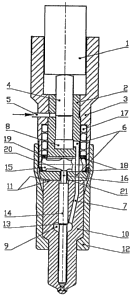
To illustrate the proposed device, Figure 1 shows a functional diagram of a
pumping unit of a
hydraulically driven pump-injector with proposed needle-spring locking device.
In Figure 1: 1- driving mechanism of the plunger; 2- plunger's bushing; 3-
pump-injector body; 4-
plunger; 5- filling channel; 6- high-pressure channel in the plunger bushing
2; 7- channel in the
nozzle body; 8- underplunger cavity; 9- high-pressure chamber in the nozzle
body; 10 - nozzle
body; 11- precision surface joints between pump-injector body and nozzle body;
12 - tightening
nut; 13 - differential cross section of the needle; 14 - nozzle needle; 15 -
transverse cross-arm; 16 -
pin of the nozzle needle;17 - return spring'of the nozzle needle ; 18 - edge
sections of cross-arm 15;
19 - spring washer ; 20 - central section of cross-arm 15; 21 - radial channel
in the plunger
bushing.
The pump-injector operates as follows:
Driving mechanism 1 forcing plunger 4 installed in bushing 2, and plunger 4
blocking filling
channel5 in body 3, the fuel in cavity 8 is expulsed via channel 6 in bushing
2 and channel 7 in the
nozzle body into chamber 9 of nozzle body 10. The sealing of channels 6 and 7
is achieved by
surface precision joint 11 between pump-injector and nozzle bodies, pressed
together by nut 12. Due
to the action of the fuel on differential cross section 13 of nozzle needle
14, needle 14 that presses
with its pin 16 on transverse cross-arm 15 disposed in cylindrical aperture of
the bushing, travels
upward overcoming the force of spring 17, arranged around the outer surface of
said plunger
bushing, whose lower face is set against the outer edges 18 of said cross-arm
15. At the end of the
needle working stroke when the pressure in chamber 9 falls, the needle due to
the action of spring 17
acting on the needle through cross-arm 15, seats on the cone of the nozzle
body. To achieve high
contact force between the cross arm 15 and the nozzle needle, while
eliminating lateral forces to act
on the needle, washer 19 is used. The edges of cross-arm 15 and central
section 20, contacting pin
3
CA 02574640 2007-01-22
WO 2006/008728 PCT/IL2004/000658
16 of needle 14, have a spherical surface. As has already been mentioned,
transverse cross-arm 15 is
disposed in the aperture of bushing 2, said aperture being perpendicular to
the bushing axis, and
radial channel 21 being made in the bushing for pin 16 of needle 14,
contacting said cross-arm, said
channel being connected with the center of said cylindrical channel. Driving
mechanism 1 of
plunger 4 can be made as a cam or hydraulically driven piston.
It will be evident to those skilled in the art that the invention is not
limited to the details of the
foregoing illustrated embodiments and that the present invention may be
embodied in other specific
-forms without departing from the spirit or essential attributes thereof. The
present embodiments are
therefore to be considered in all respect as illustrative and not restrictive,
the scope of the invention
being indicated by the appended claims rather than by the foregoing
description, and all changes
which come within the meaning and range of equivalency of the claims are
therefore intended to be
embraced therein.
BEST MODE FOR CARRYING OUT THE INVENTION
In the above embodiment shown in Figure 1, the needle is pressed against the
cross-arm with its pin
16. This allows for using conventional nozzles in the proposed spring-locking
device without any
modifications. However, it is also possible to use a needle without a pin in
the proposed device. In
this case, the needle can have a flat face, pressed against central section 20
of cross-arm 15, and said
central section of the cross-arm being pressed against the body of plunger's
bushing 2. In the first
case, the stroke of the needle is determined by stopping its face against the
precision surface of the
body, and in the second case - by stopping the central section of the cross-
arm against the pump-
injector's body. The locking device in accordance with the invention can be
realized both in the case
when the plunger is moving inside the bushing installed in pump-injector body
and also in the case
when the plunger is moving directly in the pump-injector body, having a
precision joint with the
latter. In the latter case, the cylindrical channel for the cross-arm, as well
as the radial channel for
the tail section of the nozzle needle is made directly in the pump-injector
body.
INDUSTRIAL APPLICABILITY
The spring locking device of the nozzle needle according to the invention, as
mentioned above, can
be used in diesel pump-injectors, by both methods, either the plunger being
driven by a cam, or the
plunger being forced by a hydraulically driven piston. This device is
especially efficient in a pump-
injector for high-power diesels where high injection pressures of 2000 Bar and
higher are used (for
4
CA 02574640 2007-01-22
WO 2006/008728 PCT/IL2004/000658
reasons mentioned above). The proposed loclcing device can also be used in
conventional injectors
of said diesels.