Sélection de la langue

Search

Sommaire du brevet 2574678 

Énoncé de désistement de responsabilité concernant l'information provenant de tiers

Une partie des informations de ce site Web a été fournie par des sources externes. Le gouvernement du Canada n'assume aucune responsabilité concernant la précision, l'actualité ou la fiabilité des informations fournies par les sources externes. Les utilisateurs qui désirent employer cette information devraient consulter directement la source des informations. Le contenu fourni par les sources externes n'est pas assujetti aux exigences sur les langues officielles, la protection des renseignements personnels et l'accessibilité.

Disponibilité de l'Abrégé et des Revendications

L'apparition de différences dans le texte et l'image des Revendications et de l'Abrégé dépend du moment auquel le document est publié. Les textes des Revendications et de l'Abrégé sont affichés :

  • lorsque la demande peut être examinée par le public;
  • lorsque le brevet est émis (délivrance).
(12) Demande de brevet: (11) CA 2574678
(54) Titre français: MANCHON POUR PREVENIR LA PENETRATION D'EAU
(54) Titre anglais: HYDRO PENETRATION PREVENTION SLEEVE
Statut: Morte
Données bibliographiques
(51) Classification internationale des brevets (CIB):
  • F16L 5/10 (2006.01)
  • F16L 3/10 (2006.01)
(72) Inventeurs :
  • STASKAL, JEFFERY GENE (Etats-Unis d'Amérique)
(73) Titulaires :
  • STASKAL, JEFFERY GENE (Etats-Unis d'Amérique)
(71) Demandeurs :
  • STASKAL, JEFFERY GENE (Etats-Unis d'Amérique)
(74) Agent: NA
(74) Co-agent: NA
(45) Délivré:
(22) Date de dépôt: 2007-01-22
(41) Mise à la disponibilité du public: 2008-04-17
Licence disponible: S.O.
(25) Langue des documents déposés: Anglais

Traité de coopération en matière de brevets (PCT): Non

(30) Données de priorité de la demande:
Numéro de la demande Pays / territoire Date
11/582,240 Etats-Unis d'Amérique 2006-10-17

Abrégés

Abrégé anglais


A hydro penetration prevention sleeve is used
when building a basement wall wherein said basement wall is
subject to leakage from ground water especially pipes that
have to be placed through the wall. The pipe, mostly a
sewage pipe, has to be placed into the wall at a height
which is just above the sewage pipe located outside the
building or house so that gravity can carry the sewage
toward the outside pipe. A main sleeve is placed into a
concrete casing that will form the wall just prior to
casting the concrete into the casting. The sleeve consists
of PVC and is made of two halves that interfit with each
other and are glued together to accommodate any preset
dimension that matches the preset dimension of the concrete
forms prior to casting. The main sleeve has an interior
hard rubber sleeve that has rings extending to an interior
of the sleeve and the rings are slanted in the direction of
the insertion of the pipe to be inserted therein. When the
pipe is inserted therein, the slanted rings are compressed
by the pipe. The pipe cannot be moved into the opposite
direction because of the compression and friction of the
rings. There are other elements used in sealing the ends
of the main sleeve. One embodiment can be used to seal
pipes against concrete in existing installations.

Revendications

Note : Les revendications sont présentées dans la langue officielle dans laquelle elles ont été soumises.


CLAIMS:

The embodiments of the invention in which an exclusive
property and privilege is claimed are as follows:


1. A hydro concrete to pipe sealing arrangement
consisting of a main sealing sleeve, said main sealing
sleeve consisting of two halves which interfit with each
other to accommodate variations in dimensions of a concrete
casing, said sealing sleeve having located on an interior
thereof an interior rubber sleeve, said rubber sleeve
thereby is surrounded by said main sealing sleeve, said
rubber sleeve having interiorly thereof rings facing toward
the interior, said rings are slanted in a direction of a
pipe to be inserted into said rubber sleeve to be
compressed thereby, said main sealing sleeve having at
least two hydro penetration stopping rings at an exterior
thereof and embedded in said concrete.


2. The pipe sealing arrangement of claim 1 including
at least two retainer rings embedded in said interior
rubber sleeve.


3. The pipe sealing arrangement of claim 1 including
hydro prevention penetration rings located on an exterior
of said main sealing sleeve and extending into said
concrete.


4. The pipe sealing arrangement of claim 1 including
a seal between said pipe and a wall formed by said concrete
at each end of said main sealing sleeve.


6


5. The pipe sealing arrangement of claim 4, wherein
each of said seals is a knock-out plate.


6. The pipe sealing arrangement of claim 4, wherein
one of said seals is a compression fitting plate made of
hard rubber.


7. The pipe sealing arrangement of claim 6, wherein
said compression fitting plate is installed on an already
existing pipe.


8. The pipe sealing arrangement of claim 7, wherein
said compression fitting plate consists of a plate having a
flange thereon.


9. The pipe sealing arrangement of claim 8 including
a tangential cut through said compression plate and said
flange to enable said plate and said flange to be opened to
an extent to be draped around an existing pipe.


10. The pipe sealing arrangement of claim 8 including
an exterior plate against said compression fitting plate
including means for fastening said exterior plate to said
concrete.


7

Description

Note : Les descriptions sont présentées dans la langue officielle dans laquelle elles ont été soumises.


CA 02574678 2007-01-22
HYDRO PENETRATION PREVENTION SLEEVE
BAKCGROUND OF THE INVENTION

Any building that has a below ground opening such
as a basement, will encounter ground water that may
penetrate through the basement wall even if the wall is
made of concrete. Concrete does have some kind of porous
structure. The penetration may be stopped if the outside
of the basement wall is coated with a substance like tar or
similar materials. The water penetration problem is
aggravated when a pipe is passing through the wall. Such a
pipe can be a sewer pipe which must be placed through the
basement wall at a height somewhat above the location of
the main sewer pipe which is located away from the building

or house. This arrangement will enable the sewage to flow
by gravity from the building into the main sewage pipe.
However, the pipe exiting from the basement wall is not
water proofed in any way against the influx of ground water

into the basement of the building. Various sleeves and
seals are known to prevent any ground water from entering
into the basement of a building. However, of what is known
to the applicant, none are successful to prevent the above
known problem.

BRIEF DESCRIPTION OF THE INVENTION

The inventive concept involves a sleeve of PVC
consisting of two halves that will fit within each other to
preset various lengths depending on the thickness of the
walls where it is being used. Once a proper length is

obtained, the two halves are glued to each other after
proper dimensions have been obtained when being inserted
into a casing prior to casting or pouring the concrete


CA 02574678 2007-01-22

therein. The sleeve has further attached thereto an
interior rubber seal in the form of a tube that is attached
to the sleeve by way of a hook and nose arrangement at
their respective ends. The interior rubber seal tube has

protruding therefrom a multiple of rings with their outer
circumference being directed toward the interior of the
main sleeve. However, the direction of the multiple of the
rings is directed in a slant toward the direction of a pipe
that eventually is inserted therein. The reason for this
will be explained below.

Each of the sleeves that make up the main sealing
sleeve have extended therefrom in a radial direction hydro
penetration prevention stops that will be embedded in the
concrete once the concrete casting is finished. Also, once

the concrete casting is finished, an exterior grommet seal
is attached between a pipe and the outer and inner wall of
the concrete. This seal has an exterior retainer collar.

In another embodiment of the invention there is
shown a sealing arrangement that is to be used on an

already existing pipe in a concrete wall. This arrangement
consists of an exterior grommet seal that has a flange
thereon. This seal is made of hard rubber, yet, it remains
flexible so that the grommet seal can be slipped over the
existing pipe by way of a tangential cut that can be opened

so that it can be slipped over the existing pipe but will
seal again once it is in place around the pipe. The
grommet seal is held in place and against the concrete wall
by way of a retainer plate which is held in place by screws
that penetrate through the plate and into the concrete

wall. Additionally, the flange on the grommet seal is
completely sealed by way of a hose clamp which will

2


CA 02574678 2007-01-22

compress the flange and the previously tangential cut in to
a complete sealing condition.

BRIEF DESCRIPTION OF THE DRAWINGS

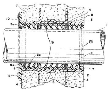
Figure 1 is a cross section through the concrete
wall and pipe arrangement;

Figure 2 shows an element of the sealing
arrangement of Figure 1 in a plan and a cross sectional
view;

Figure 3 is a side view of a different embodiment
of the invention which is directed to a retrofit of a pipe
in a concrete wall; and

Figure 4 is a perspective view of the different
embodiment of Figure 3.

DETAILED DESCRIPTION OF THE INVENTION
Figure 1 shows the present invention in a cross
section view. At 1 is shown a pipe that will eventually be
installed in the basic sealing unit 2. The basic sealing

unit 1 consists of two half sections 2 and 2a which will
slip into each at 6 and will be glued together at that
point when proper dimensions of 8 to 12 inches have been
obtained at this point of construction. Different wall
thicknesses will require different lengths. The basic

sealing unit has included therein an interior rubber seal 3
which is supported within the basic sealing unit 2 by way
of a cradle 4. The interior rubber seal 3 further has
embedded therein retainer or reinforcing rings 7 which are
designed to keep the circular shape of the interior rubber
seal 3 before, during and after the installation of the
interior rubber seal. The cradle 4 is designed to keep a
3


CA 02574678 2007-01-22

concentricity between the pipe 1 and the interior rubber
seal 3 during installation.

On the outside of the basic sealing unit 2 there
are provided extended PVC rings 5 which act as a

penetration stop of water through the wall and past the
basic sealing unit.

The basic interior rubber seal 3 further includes
hydro prevention rings 13 which are slanted in the
direction of the pipe 1 insertion so that their slant

direction contributes to a pressure sealing because of the
deflection pressure induced when pushing the pipe 1 through
the interior rubber seal.

The outer concrete wall is sealed against any
leakage past the pipe 1 by way of using an exterior grommet
seal 9 (Figure 2) which has a nose 9a which when pushed

(forced) into the basic sealing unit 2 will lock into the
basic sealing unit 2 by way of the hook and nose
arrangement 9 and 9a. The grommet seal 9 is pressed
against the concrete wall by way of an exterior retainer
plate 10 which is fastened and forced against the concrete
wall by way of the fastening and anchoring screws 12.

Both ends of the basic sealing unit 2 are sealed
against concrete leaking into the same by way of the knock-
out plate 8 which has a thinned area 8a for a tool to be
applied to easily knock-out the plate.

Figure 4 illustrates a different embodiment of
the invention which is considered a retrofit for an
existing pipe 27 in a concrete wall 26. As in the previous
embodiment there is an exterior grommet seal 20 having a
tangential cut 24b therein. This enables a person to
install the grommet seal 20 by simply bending the seal in
two different directions to obtain an opening to enable the

4


CA 02574678 2007-01-22

opening to be slipped over the circumference of an existing
pipe. The grommet seal 20 has a flange thereon which also
has a tangential cut 24a therein so that it may be opened
with the cut 24b to be able to be slipped over an existing

pipe 27. The tangential cuts 24a and 24b are in the same
direction so that the grommet seal 20 can be opened to
accommodate the pipe circumference when installing the same
around the pipe 27. There is an exterior retainer plate 29
which is installed in such a manner so that it presses

against the exterior grommet seal 20 by way of screws 28
which are screwed into the concrete with proper pressure to
make the seal leak proof. The flange 20a is also
compressed by way of a hose pressure clamp 23 which will
compress the flange and the tangential cut 24a to render

both of them to be leak proof.

5

Dessin représentatif
Une figure unique qui représente un dessin illustrant l'invention.
États administratifs

Pour une meilleure compréhension de l'état de la demande ou brevet qui figure sur cette page, la rubrique Mise en garde , et les descriptions de Brevet , États administratifs , Taxes périodiques et Historique des paiements devraient être consultées.

États administratifs

Titre Date
Date de délivrance prévu Non disponible
(22) Dépôt 2007-01-22
(41) Mise à la disponibilité du public 2008-04-17
Demande morte 2011-01-24

Historique d'abandonnement

Date d'abandonnement Raison Reinstatement Date
2010-01-22 Taxe périodique sur la demande impayée

Historique des paiements

Type de taxes Anniversaire Échéance Montant payé Date payée
Le dépôt d'une demande de brevet 200,00 $ 2007-01-22
Taxe de maintien en état - Demande - nouvelle loi 2 2009-01-22 50,00 $ 2009-01-22
Titulaires au dossier

Les titulaires actuels et antérieures au dossier sont affichés en ordre alphabétique.

Titulaires actuels au dossier
STASKAL, JEFFERY GENE
Titulaires antérieures au dossier
S.O.
Les propriétaires antérieurs qui ne figurent pas dans la liste des « Propriétaires au dossier » apparaîtront dans d'autres documents au dossier.
Documents

Pour visionner les fichiers sélectionnés, entrer le code reCAPTCHA :


Pour visualiser une image, cliquer sur un lien dans la colonne description du document. Pour télécharger l'image (les images), cliquer l'une ou plusieurs cases à cocher dans la première colonne et ensuite cliquer sur le bouton "Télécharger sélection en format PDF (archive Zip)" ou le bouton "Télécharger sélection (en un fichier PDF fusionné)".

Liste des documents de brevet publiés et non publiés sur la BDBC .

Si vous avez des difficultés à accéder au contenu, veuillez communiquer avec le Centre de services à la clientèle au 1-866-997-1936, ou envoyer un courriel au Centre de service à la clientèle de l'OPIC.


Description du
Document 
Date
(yyyy-mm-dd) 
Nombre de pages   Taille de l'image (Ko) 
Revendications 2007-01-22 2 55
Description 2007-01-22 5 179
Abrégé 2007-01-22 1 33
Dessins 2007-01-22 4 154
Dessins représentatifs 2008-03-17 1 35
Page couverture 2008-04-11 2 79
Cession 2007-01-22 4 129
Taxes 2009-01-22 1 44