Sélection de la langue

Search

Sommaire du brevet 2576656 

Énoncé de désistement de responsabilité concernant l'information provenant de tiers

Une partie des informations de ce site Web a été fournie par des sources externes. Le gouvernement du Canada n'assume aucune responsabilité concernant la précision, l'actualité ou la fiabilité des informations fournies par les sources externes. Les utilisateurs qui désirent employer cette information devraient consulter directement la source des informations. Le contenu fourni par les sources externes n'est pas assujetti aux exigences sur les langues officielles, la protection des renseignements personnels et l'accessibilité.

Disponibilité de l'Abrégé et des Revendications

L'apparition de différences dans le texte et l'image des Revendications et de l'Abrégé dépend du moment auquel le document est publié. Les textes des Revendications et de l'Abrégé sont affichés :

  • lorsque la demande peut être examinée par le public;
  • lorsque le brevet est émis (délivrance).
(12) Brevet: (11) CA 2576656
(54) Titre français: TUBE DE RACCORDEMENT D'EAU FROIDE ET D'EAU CHAUDE POUR ROBINETS EN PLASTIQUE
(54) Titre anglais: COLD AND HOT WATER CONNECTING TUBE STRUCTURE FOR PLASTIC FAUCETS
Statut: Réputé périmé
Données bibliographiques
(51) Classification internationale des brevets (CIB):
  • F16L 15/08 (2006.01)
  • E03C 1/04 (2006.01)
  • F16L 47/16 (2006.01)
(72) Inventeurs :
  • CHANG, KIM (Taïwan, Province de Chine)
(73) Titulaires :
  • CHANG, KIM (Taïwan, Province de Chine)
(71) Demandeurs :
  • CHANG, KIM (Taïwan, Province de Chine)
(74) Agent: RIDOUT & MAYBEE LLP
(74) Co-agent:
(45) Délivré: 2009-08-25
(22) Date de dépôt: 2007-02-01
(41) Mise à la disponibilité du public: 2008-08-01
Requête d'examen: 2007-02-01
Licence disponible: S.O.
(25) Langue des documents déposés: Anglais

Traité de coopération en matière de brevets (PCT): Non

(30) Données de priorité de la demande: S.O.

Abrégés

Abrégé français

Le présent extrait concerne un tube de raccordement d'eau froide et d'eau chaude pour robinets en plastique, qui comprend un connecteur et une conduite d'entrée. Le connecteur comprend une partie tubulaire et une collerette de butée de diamètre supérieur avec un tube fileté de diamètre inférieur moulé solidairement dépassant vers le bas à l'autre extrémité. Le tube fileté a une bague étanche montée sur une gorge annulaire définissant une position appropriée dessus pour former un ensemble de flasques de calage des deux côtés. La conduite d'entrée a une découpe de guidage oblique à un bord d'extrémité pour buter étanche contre un joint hydraulique monté dans une tête de blocage d'un tuyau d'eau froide/chaude, et une section accolée avec une section à filetage interne définissant la surface interne de l'autre extrémité. Le tube de raccordement peut donc être joint avec précision sans aucune fissure provoquée par la contraction due au froid pour assurer un raccordement sûr. Sa conception du type séparé permet également un montage et un remplacement faciles de cette invention.


Abrégé anglais

A cold and hot water connecting tube structure for plastic faucets comprises a connector and an inlet duct. The connector includes a tubular portion and a larger-diameter stop flange with a smaller-diameter threaded tube integrally molded to protrude downwards at the other end. The threaded tube has a watertight ring mounted to an annular groove defining an appropriate position thereon to form a set of abutment flanges at both sides. The inlet duct has an oblique guide slope cut at one end edge to abut tight against a water-sealing ring mounted inside a locking head of a cold/hot water pipe, and a conjoining section with an internal-threaded section defining the internal surface of the other end. Therefore, the connecting tube can be accurately joined without any chinks caused by cold-contraction to ensure secure connection thereby. And the separate-type design thereof also permits easy assembly and replacement of the present invention.

Revendications

Note : Les revendications sont présentées dans la langue officielle dans laquelle elles ont été soumises.


CLAIMS
What is claimed is:

1. A cold and hot water connecting tube structure for plastic faucets,
comprising a
coupling tube equipped with a valve seat for the accommodation of a control
valve
therein, a spout mounted to the outer side of the valve seat, a locking cap,
and a
handle to regulate the discharge and shutoff of water flow thereby wherein the

coupling tube has both end sides respectively mounted with a waterproof ring
thereon
and joined to a cold/hot water connecting tube thereby; the present invention
being
characterized by that,

--the cold/hot water connecting tube being composed of a connector and an
inlet duct
wherein the connector, molded into an L shape, is made up of a tubular portion

extending at one side to mount to the coupling tube thereby, and a larger-
diameter
stop flange with a smaller-diameter threaded tube integrally molded to
protrude
downwards at the other end thereon; the threaded tube having an annular groove

indented at an appropriate position thereon for the accommodation of a
watertight ring
therein, and a set of abutment flanges symmetrically protruding to define both
sides of
the annular groove thereby;

--the inlet duct having an oblique guide slope cut at one internal end edge
thereon to
abut tight and close against a water-sealing ring mounted inside a locking
head of a
cold/hot water pipe; the inlet duct also has the internal surface of the other
end
equipped with a conjoining section, an internal-threaded section, and an
oblique
tapered guide surface disposed between the conjoining section and the
internal-threaded section thereon; therefore, the threaded tube of the
connector can be
led along the guide surface to lock to the internal-threaded section till the
abutment
flanges of the threaded tube are securely coupled with the conjoining section
and
restricted in position by the guide surface thereof.

6


2. The cold and hot water connecting tube structure for plastic faucets as
claimed in
Claim 1 wherein the stop flange of the connector has multiple assembly holes
extending through the outer periphery thereon to match to through holes
disposed at a
base board of a mount and securely rivet-join thereto.

3. The cold and hot water connecting tube structure for plastic faucets as
claimed in
Claim 1 wherein the inlet duct is molded of copper element thereof.

4. The cold and hot water connecting tube structure for plastic faucets as
claimed in
Claim 1 wherein the inlet duct is equipped with a polygonal tool notch
defining the
interior of one end thereon.

5. The cold and hot water connecting tube structure for plastic faucets as
claimed in
Claim 1 wherein the threaded tube of the connector is equipped with
reinforcing ribs
extending at the internal surface thereon.

6. The cold and hot water connecting tube structure for plastic faucets as
claimed in
Claim 5 wherein the reinforcing ribs extending inside the threaded tube
thereof can be
molded in cross-shaped configuration.

7

Description

Note : Les descriptions sont présentées dans la langue officielle dans laquelle elles ont été soumises.


CA 02576656 2007-02-01

COLD AND HOT WATER CONNECTING TUBE STRUCTURE FOR PLASTIC
FAUCETS
BACKGROUND OF THE INVENTION

The present invention relates to a cold and hot water connecting tube
structure
for plastic faucets, comprising a connector and an inlet duct wherein the
connector
having a threaded tube with abutment flanges extending thereon is securely
locked to
the inlet duct having an internal-threaded section with a conjoining section
defining
thereon to form a separate-type design and provide secure engagement without
any
chinks caused by cold-contraction, facilitating easier assembly and
replacement to
achieve both economical and environmental benefits thereby.'

A conventional plastic faucet 10 as shown in Fig. 1 includes a cold and hot
water connecting tube 11 that is ejection molded and integrally bound with a
metallic
outer tube 111 having a threaded section defining thereon to form a plastic-
metallic
layer of an inner tube 112 at the internal wall thereby. However, during the
process
of production, the fmished inner tube 112 will cool off and become deformed
due to
the phenomena of heat-expansion and cold-contraction. As a result, the inner
tube
112 will contract inwards and fail to keep an even surface with the opening
edge of
the outer tube 111 thereof. And when a locking head 21 of a cold/hot water
pipe 20
is fixed to the outer tube I11, a sealing ring 22 can simply abut against the
end edge
of the outer tube 111, which relatively reduces the sealing area and affects
secure
engagement there-between. Thus, the cold and hot water connecting tube 11
cannot
accurately bear the force of water pressure and can easily result in water
leakage.
Furthermore, the inner tube 112, contracted and deformed after cooling off, is
poorly
combined with the outer tube 111, which can cause a chink A revealed there-
between
1


CA 02576656 2007-02-01

and fail to provide secure connection thereof. Finally, the inner and outer
tubes 112,
111 of the cold and hot water connecting tube 11 are integrally bound and
coupled
with a set of perpendicular-extending tubular portion 113 and a water-guiding
duct B.
Thus, for maintenance, the cold and hot water connecting tube 11 must be
dismantled
and replaced as a whole, which is quite uneconomical and eco-unfriendly.

SUMMARY OF THE PRESENT INVENTION

It is, therefore, the primary purpose of the present invention to provide a
cold
and hot water connecting tube structure for plastic faucets wherein a
connector having
a threaded tube with abutment flanges extending thereon is securely locked to
an inlet
duct having an internal-threaded section with a conjoining section defining
thereon to
form a separate-type design, which can not only provide securer connection to
avoid
any chinks caused by cold-contraction thereof, but also facilitate easier
assembly and
replacement to achieve both economical and environmental benefits thereby.

It is, therefore, the second purpose of the present invention to provide a
cold
and hot water connecting tube structure for plastic faucets wherein the inlet
duct has
an oblique guide slope cut at one end edge thereon to abut tight against a
water-sealing ring mounted inside a locking head of a cold/hot water pipe;
whereby,
the water-sealing ring will simultaneously contact tight and close both the
end edge
and the oblique guide slope of the inlet duct, efficiently boosting the water-
sealing
area and reinforcing secure connection so as to accurately bear the force of
water
pressure and ensure watertight benefit thereby.

BRIEF DESCRIPTION OF THE DRAWINGS
2


CA 02576656 2007-02-01

Fig. I is an assembled flat view of a conventional cold and hot water
connecting tube
for plastic faucets.

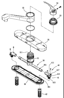
Fig. 2 is an exploded perspective view of the present invention.

Fig. 3 is an exploded perspective view of a cold/hot water connecting tube of
the
present invention.

Fig. 4 is an assembled perspective view of the present invention.
Fig. 5 is an assembled cross sectional view of the present invention.
Fig. 6 is an assembled cross sectional view of Fig. 3.

Fig. 7 is an exploded perspective view of another cold/hot water connecting
tube of
the present invention.

DETAILED DESCRIPTION OF THE PREFERRED EMBODIMENTS

Please refer to Fig. 2 showing an exploded perspective view of the present
invention (accompanied by Figs. 3 to 5 inclusive). The present invention
relates to a
cold and hot water connecting tube structure for plastic faucets, comprising a
coupling
tube 30 equipped with a valve seat 31 for the accommodation of a control valve
311
therein, a spout 32 mounted to the outer side of the valve seat 31, a locking
cap 33,
and a handle 34 to regulate the discharge and shutoff of water flow thereby.
The
coupling tube 30 has both end sides respectively mounted with a waterproof
ring 301
thereon and joined to a cold/hot water connecting tube 40 thereby. The
cold/hot
water connecting tube 40 is composed of a connector 41 and an inlet duct 42.
The
connector 41, molded into an L shape, is made up of a tubular portion 411
extending
at one side to mount to the coupling tube 30 thereby, and a larger-diameter
stop flange
412 with a smaller-diameter threaded tube 413 integrally molded to protrude
downwards at the other end thereon. The threaded tube 413 has an annular
groove
3


CA 02576656 2007-02-01

414 indented at an appropriate position thereon for the accommodation of a
watertight
ring 415 therein, and a set of abutment flanges 416 symmetrically protruding
to define
both sides of the annular groove 414 thereby. The stop flange 412 has multiple
assembly holes 417 extending through the outer periphery thereon to match to
through
holes 361 disposed at a base board 36 of a mount 35 and rivet-join thereto.
The inlet
duct 42, molded of copper element, is equipped with a polygonal tool notch 421
defuiing the internal surface of one end thereon, and an oblique guide slope
422 cut at
the internal end edge thereon. The inlet duct 42 has the internal surface of
the other
end equipped with a conjoining section 423, an internal-threaded section 424,
and an
oblique tapered guide surface 425 disposed between the conjoining section 423
and
the internal-threaded section 424 thereon. Therefore, the threaded tube 413 of
the
connector 41 (referring to Fig. 6) can be guided from top to bottom to
accommodate
into the inlet duct 42, sliding smoothly along the guide surface 425 to
securely lock to
the internal-threaded section 424 and form the first layer of connection
thereby.
Then, the abutment flanges 416 of the threaded tube 413 can also be tightly
mounted
into the conjoining section 423 till restrained in position by the guide
surface 425 to
form the second layer of connection, achieving better and securer engagement
thereby.
Meanwhile, the watertight ring 415 is limited in place by the, abutment
flanges 416 to
accurately seal tight and close onto the inner wall of the conjoining section
423.
Moreover, when the inlet duct 42 is fixed to a locking head 51 of a cold/hot
water
pipe 50, a water-sealing ring 52 will closely abut against both the end edge
and the
oblique guide slope 422 thereof, reinforcing secure connection thereof to bear
the
force of water pressure and ensure the watertight benefit thereby.

Please refer to Fig. 7. The threaded tube 413 of the connector 41 can also be
equipped with cross-shaped reinforcing ribs 418 extending at the internal
surface
thereon so as to strengthen the assembly of the inlet duct 42 and the threaded
tube 413
4


CA 02576656 2007-02-01

as a whole and boost their durability thereby.

Dessin représentatif
Une figure unique qui représente un dessin illustrant l'invention.
États administratifs

Pour une meilleure compréhension de l'état de la demande ou brevet qui figure sur cette page, la rubrique Mise en garde , et les descriptions de Brevet , États administratifs , Taxes périodiques et Historique des paiements devraient être consultées.

États administratifs

Titre Date
Date de délivrance prévu 2009-08-25
(22) Dépôt 2007-02-01
Requête d'examen 2007-02-01
(41) Mise à la disponibilité du public 2008-08-01
(45) Délivré 2009-08-25
Réputé périmé 2012-02-01

Historique d'abandonnement

Il n'y a pas d'historique d'abandonnement

Historique des paiements

Type de taxes Anniversaire Échéance Montant payé Date payée
Requête d'examen 400,00 $ 2007-02-01
Le dépôt d'une demande de brevet 200,00 $ 2007-02-01
Taxe de maintien en état - Demande - nouvelle loi 2 2009-02-02 50,00 $ 2008-12-23
Taxe finale 150,00 $ 2009-05-25
Taxe de maintien en état - brevet - nouvelle loi 3 2010-02-01 50,00 $ 2010-01-29
Titulaires au dossier

Les titulaires actuels et antérieures au dossier sont affichés en ordre alphabétique.

Titulaires actuels au dossier
CHANG, KIM
Titulaires antérieures au dossier
S.O.
Les propriétaires antérieurs qui ne figurent pas dans la liste des « Propriétaires au dossier » apparaîtront dans d'autres documents au dossier.
Documents

Pour visionner les fichiers sélectionnés, entrer le code reCAPTCHA :


Pour visualiser une image, cliquer sur un lien dans la colonne description du document. Pour télécharger l'image (les images), cliquer l'une ou plusieurs cases à cocher dans la première colonne et ensuite cliquer sur le bouton "Télécharger sélection en format PDF (archive Zip)" ou le bouton "Télécharger sélection (en un fichier PDF fusionné)".

Liste des documents de brevet publiés et non publiés sur la BDBC .

Si vous avez des difficultés à accéder au contenu, veuillez communiquer avec le Centre de services à la clientèle au 1-866-997-1936, ou envoyer un courriel au Centre de service à la clientèle de l'OPIC.


Description du
Document 
Date
(yyyy-mm-dd) 
Nombre de pages   Taille de l'image (Ko) 
Abrégé 2007-02-01 1 25
Description 2007-02-01 5 192
Revendications 2007-02-01 2 76
Dessins 2007-02-01 7 137
Dessins représentatifs 2008-07-25 1 13
Page couverture 2008-07-28 2 51
Dessins représentatifs 2009-07-30 1 16
Page couverture 2009-07-30 2 53
Cession 2007-02-01 2 68
Correspondance 2007-10-17 2 40
Taxes 2008-12-23 1 35
Correspondance 2009-05-25 1 34
Taxes 2010-01-29 1 39