Note : Les descriptions sont présentées dans la langue officielle dans laquelle elles ont été soumises.
CA 02576909 2007-02-12
WO 2006/022877 PCT/US2005/011411
DISPENSER FOR MULTIPLE ROLLS OF SHEET MATERIAL
BACKGROUND
Dispensers for bath tissue used in institutional and public restrooms are
often configured
to provide a "jumbo" roll of sheet material or bath tissue therein. For
increased capacity
and to extend the time between restocking, some of these dispensers are
configured to
accommodate a second, or backup, jumbo roll, which is disposed alongside the
primary
jumbo roll. It would be advantageous to have a dispenser that would
accommodate a
backup jumbo roll, yet restrict a user from dispensing sheet material from the
backup roll
prior to substantial depletion of the primary roll.
DEFINITIONS
As used herein, the term "exit port" or "dispensing opening" is the opening in
a housing of
a dispenser for the passage of sheet material out of the dispenser.
As used herein, the term "fasteners" means devices that fasten, join, connect,
secure,
hold, or clamp components together. Fasteners include, but are not limited to,
screws,
nuts and bolts, rivets, tape, snap-fits, tacks, nails, loop fasteners, and
interlocking
male/female connectors, such as fishhook connectors. A fish hook connector
includes a
male portion with a protrusion on its circumference. Inserting the male
portion into the
female portion substantially permanently locks the two portions together.
As used herein, the term "hinge" refers to a jointed or flexible device that
connects and
permits pivoting or turning of a part to a stationary component. Hinges
include, but are
not limited to, metal pivotable connectors, such as those used to fasten a
door to frame,
spring-loaded hinges, living hinges, and so forth. Living hinges may be
constructed from
plastic and other materials and formed integrally between two members. A
living hinge
permits movement, such as, but not by way of limitation, pivotable movement,
of one
member in relation to another connected member.
As used herein, the term "sheet material" means a material that is thin in
comparison to its
length and breadth. Generally speaking, sheet materials should exhibit a
relatively flat
planar configuration and be flexible to permit folding, rolling, stacking, and
the like.
Exemplary sheet materials include, but are not limited to, paper tissue,
bath/toilet tissue,
paper towels, wipes, label rolls, or other fibrous, film, or filamentary
products.
1
CA 02576909 2011-03-31
SUMMARY OF THE INVENTION
In one embodiment, a dispenser for storing and dispensing rolled sheet
material includes
a housing configured to rotationally support a primary roll of sheet material
and a backup
roll of sheet material inside the housing. The housing also includes an exit
port. The
dispenser further includes a dispensing control member moveably positioned
substantially within and partially blocking the exit port. The dispensing
control member is
configured to substantially restrict rotation of the backup roll of sheet
material prior to
substantial depletion of the primary roll of sheet material. In another
embodiment, the
dispensing control member includes at least one projection positioned on an
inside
surface of the dispensing control member. The projection substantially
restricts rotation
of the backup roll of sheet material. In another embodiment, the dispensing
control
member includes a plurality of projections positioned on the inside surface of
the
dispensing control member.
In a further embodiment, a dispenser for storing and dispensing rolled sheet
material
includes a housing having an interior and configured to rotationally support a
primary roll
of sheet material and a backup roll of sheet material therein. The housing is
formed to
include an exit port positioned to allow insertion of the primary roll of
sheet material and
the backup roll of sheet material into the housing interior. The dispenser
further includes
a dispensing control member moveably positioned substantially within and
partially
blocking the exit port. The dispensing control member includes a divider
extending into
the housing interior between the primary roll of sheet material and the backup
roll of sheet
material to a distance sufficient to substantially restrict movement of the
dispensing
control member prior to substantial depletion of the primary roll of sheet
material. The
dispensing control member further includes a plurality of ribs positioned on
an inside
surface of the dispensing control member. The ribs are positioned to
substantially restrict
rotation of the backup roll of sheet material prior to substantial depletion
of the primary roll
of sheet material.
In an even further embodiment, a dispenser for storing and dispensing rolled
sheet
material includes a housing configured to rotationally support a primary roll
of sheet
material and a backup roll of sheet material therein. The dispenser further
includes a
means for substantially restricting rotation of the backup roll of sheet
material prior to
substantial depletion of the primary roll of sheet material.
2
CA 02576909 2011-03-31
In a further embodiment, there is provided a dispenser for storing and
dispensing rolled
sheet material, comprising: a housing having an interior and configured to
rotationally
support a primary roll of sheet material and a backup roll of sheet material
therein, the
housing formed to include an exit port, the exit port positioned to allow
insertion of the
primary roll of sheet material and the backup roll of sheet material into the
housing
interior; and a dispensing control member moveably positioned substantially
within and
partially blocking the exit port, the dispensing control member comprising: a
divider
extending into the housing interior between the primary roll of sheet material
and the
backup roll of sheet material to a distance sufficient to substantially
restrict movement of
the dispensing control member prior to substantial depletion of the primary
roll of sheet
material; and a plurality of ribs positioned on an inside surface of the
dispensing control
member, the ribs positioned to substantially restrict rotation of the backup
roll of sheet
material prior to substantial depletion of the primary roll of sheet material.
In a further embodiment, there is provided a method of loading rolls of sheet
material in a
dispenser adapted to hold at least two rolls of sheet material, the method
comprising
providing the dispenser as set out above, disposing a primary roll of sheet
material and a
backup roll of sheet material within the housing, and moving the dispensing
control
member to a position wherein rotation of the backup roll of sheet material is
substantially
restricted. In another embodiment, the method comprises disposing a primary
roll of
sheet material in a backup roll of sheet material within the housing, and
sliding the
dispensing control member to a position wherein rotation of the backup roll of
sheet
material is substantially restricted by at least one rib.
BRIEF DESCRIPTION OF THE DRAWINGS
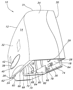
FIG. 1 is a perspective view of an embodiment of a dispenser;
FIG. 2 is a cross-sectional end view of the dispenser of FIG. 1;
2a
CA 02576909 2007-02-12
WO 2006/022877 PCT/US2005/011411
FIG. 3 is a cross-sectional front view of the dispenser of FIG. 1;
FIG. 4 is a perspective view of an embodiment of a dispensing control member;
and
FIGS. 5-7 are schematic operational front views of an embodiment of a
dispenser.
DETAILED DESCRIPTION
Reference will now be made in detail to the embodiments of the invention, one
or more
examples of which are set forth below and illustrated in the drawings. Each
example is
provided by way of explanation of the invention and is not meant as a
limitation of the
invention. For example, features illustrated and described as part of one
embodiment or
figure can be used on another embodiment or figure to yield yet another
embodiment. It
is intended that the present invention include such modifications and
variations.
As illustrated in FIGS. 1-3, the dispenser 10 includes a housing 12 having an
exterior
surface 14 and an interior surface 16. The housing 12 defines an internal
compartment 18 within which the housing is capable of rotationally supporting
a first, or
primary, roll of paper 20 and a second, or backup roll of paper 22. The
housing 12 further
defines a dispensing opening or exit port 24 which provides a user access to
the sheet
material on the paper rolls. Desirably, the exit port 24 is substantially
rectangular in
shape, and permits loading of the paper rolls through the exit port. In the
present
embodiment, but not by way of limitation, the exit port 24 is provided in a
lower portion 26
of the housing 12. Desirably, a perimeter 28 of the exit port 24 includes at
least one
serrated portion 29 to permit sections of sheet material to be severed and
removed from
one or more rolls of sheet material disposed in the internal compartment 18 of
the housing
12.
The housing 12 generally includes a top wall 31 contiguous with a back wall
30, an
opposing front wall 32, and a pair of spaced-apart opposing side walls 34. The
back
wall 30 is configured to be mounted on a surface or wall, such as, by way of
non-limiting
example, the wall of a toilet stall (not shown). The back wall 30 defines a
plurality of
openings 36 to permit such mounting via fasteners, brackets, hinges,
adhesives, and so
forth.
The front wall 32 defines a window opening 38 provided therein. A window plate
40 is
mounted on an inner surface 42 of the front wall 32 over the window opening
38. The
window plate 40 may be, for example, but not by way of limitation, clear,
transparent,
tinted, and so forth, to provide a view of the size and amount of the
remaining rolls of
sheet material in the dispenser 10 to a user or a maintenance technician. It
will be
3
CA 02576909 2007-02-12
WO 2006/022877 PCT/US2005/011411
appreciated, however, that any portion(s) of the housing 12 may be clear,
transparent,
tinted, opaque, and so forth.
It will be appreciated that in the present embodiment, the configuration of
the housing 12
is not intended as a limitation; other configurations may be used to
accommodate
aesthetic and/or functional considerations.
As described above, the dispenser 10 and housing 12 are desirably configured
to hold at
least two rolls of sheet material, for example, the primary roll of sheet
material 20 and the
backup roll of sheet material 22. Such sheet material is often flexible, such
as toilet or
bath tissue and so forth. Each roll 20, 22 may be wound throughout its
diameter about a
longitudinal open core or may be coreless, and each roll forms, generally, a
cylinder
having opposing flat ends 48 and an outer circumferential surface 50. The
sheet material
forming the rolls 20, 22 is desirably non-perforated sheet material, although
sheet material
perforated into sheet sections of predetermined length may also be used.
A first pair of mandrels/hubs 44 and a second pair of mandrels/hubs 46 are
mounted on
the housing 12, each pair including a mandrel/hub on the front wall 32 and the
back
wall 30. The first pair of hubs 44 holds the primary roll of sheet material 20
and the
second pair of hubs 46 holds the backup roll of sheet material 22. The rolls
20, 22 are
positioned on the hubs 44, 46 such that the center 52 of each roll 20, 22 is
mounted on a
hub 44, 46 and each roll 20, 22 is mounted with its outer circumferential
surface 50
adjacent the other. One flat end 48 of each roll 20, 22 is positioned adjacent
the back
wall 30 while the opposite flat end 48 of each roll 20, 22 is positioned
adjacent the front
wall 32. The pairs of mandrels/hubs 44, 46 are configured to rotationally
support the rolls
of sheet material 20, 22. The mandrels/hubs 44, 46 may be fixed or may rotate
along with
the rolls of sheet material 20, 22. Support arms 54, desirably cantilevered
support arms,
may be attached to the interior surface 16 of the housing 12 to provide
further support to
the rolls of sheet material 20, 22. In one embodiment, the mandrels/hubs 44,
46 may be
cantilevered on an end of the support arm 54. The support arms 54 are
configured to
apply pressure against and support the flat ends 48 of the rolls of sheet
material 20, 22.
Desirably, the dispenser 10 of the present embodiment is generally designed to
hold a
pair of large, or jumbo, rolls. A jumbo roll is generally, but not by way of
limitation,
considered to have a diameter greater than about 8 inches. It will be
appreciated that the
dispenser 10 and the housing 12 may be sized to include additional hubs to
hold
additional rolls of larger or smaller roll sizes as well as combinations of
roll sizes.
4
CA 02576909 2007-02-12
WO 2006/022877 PCT/US2005/011411
Referring now to FIGS. 1-4, the dispenser 10 further includes a dispensing
control
member 60. The dispensing control member 60 is moveably attached to the
housing 12.
The dispensing control member 60 is desirably positioned within or near the
exit port 24,
and partially blocks the exit port. Desirably, the dispensing control member
60 includes at
least one serrated portion 29 to permit sections of sheet material to be
severed and
removed from one or more rolls of sheet material disposed in the internal
compartment 18
of the housing 12. The dispensing control member 60 is capable of moving in a
primary
direction of travel between a first end 62 of the exit port 24 (at which
position the
dispensing control member leaves exposed the second (or backup) roll of sheet
material
22) to a second end 64 of the exit port (at which position the dispensing
control member
leaves exposed the first (or primary) roll of sheet material 20). In one
embodiment, the
dispensing control member 60 is partially supported upon the housing 12 by
tabs 66 on an
outside surface 68 of the dispensing control member. As one example, the tabs
66 may
be arranged adjacent first and second sides 69, 70 of a lip 72 formed in the
perimeter 28
of the exit port 24. As another example, the tabs 66 may slidingly rest on a
ridge 74
formed on the interior surface 16 on or near the lower portion 26 of the
housing 12. To
slidingly restrain the dispensing control member 60, a projection 76 on the
dispensing
control member may be slidingly restrained within a slot 78 in the housing 12
by a fastener
(not shown). The slot 78 may include one or more slight restrictions (not
shown) to
partially restrict movement of the retaining fastener within the slot.
Additional force is
required to move the fastener past the restriction. For example, restrictions
in the slot 78
near the ends of the slot may be used to in effect lock the dispensing control
member 60
into position at either end of the exit port 24.
The dispensing control member 60 is desirably configured to substantially
restrict rotation
of the backup roll of sheet material 22 prior to substantial depletion of the
primary roll of
sheet material 20 when the dispensing control member 60 is positioned towards
the
second end 64 of the exit port 24. As such, the dispensing control member 60
desirably
includes a means for substantially restricting rotation of the backup roll 22
prior to
substantial depletion of the primary roll 20. In one embodiment, the
dispensing control
member 60 includes at least one projection 80 positioned on an inside surface
82 of the
dispensing control member. In another embodiment, the inside surface 82 may
contact
the backup roll 22 when the dispensing control member 60 is positioned towards
the
second end 64 of the exit port 24 and thus substantially restrict rotation of
the backup roll.
In a further embodiment, the inside surface 82 may be roughened to increase
friction
against the outer circumferential surface 50 of the backup roll 22 to
substantially restrict
5
CA 02576909 2007-02-12
WO 2006/022877 PCT/US2005/011411
rotation of the backup roll. By "substantially restrict rotation", it is meant
that the backup
roll 22 will be restrained such that force applied to the tail of sheet
material extending from
the backup roll will cause the sheet material to break rather than causing the
roll to rotate
and dispense additional sheet material. In other embodiments, the dispensing
control
member may more fully restrict or prevent rotation of the backup roll 22.
Desirably, the projection 80 includes a triangular rib 84. More desirably, an
edge 86 of the
triangular rib 84 may be attached to the inside surface 82 of the dispensing
control
member 60 wherein the attached edge 86 is oriented parallel to the primary
direction of
travel of the dispensing control member. Even more desirably, the attached
edge 86 is
shorter than a first unattached edge 88 and a second unattached edge 90 of the
triangular
rib 84 extending from the inside surface 82 of the dispensing control member
60.
Desirably, the dispensing control member 60 will include a plurality of
projections 80
positioned on the inside surface 82 of the dispensing control member 60. More
desirably,
the plurality of projections 80 are arranged in rows 92 with each row having
at least two
projections. In some embodiments, the rows 92 may have two, three, four, or
more
projections. When there is more than one row 92, the rows may have equal or
unequal
numbers of projections 80. The rows 92 are desirably positioned substantially
perpendicular to the primary direction of travel of the dispensing control
member 60, but
may be positioned at other angles with respect to the primary direction of
travel of the
dispensing control member.
In one embodiment, the dispensing control member 60 further includes a divider
94
extending into the interior compartment 18 of the housing 12 between the
primary roll of
sheet material and the backup roll of sheet material. The divider 94 desirably
extends to a
distance sufficient to substantially restrict movement of the dispensing
control member 60
in a primary direction of travel prior to substantial depletion of the primary
roll of sheet
material 20. Therefore, the movement of the dispensing control member 60 is
restricted
according to the size of the primary roll of sheet material 20 as shown in
FIGS. 5-7.
When the primary roll of sheet material 20 is at its largest size as shown in
FIG. 5, the
divider 94 allows relatively little movement of the dispensing control member
60 from its
position below the backup roll of sheet material 22. As sheet material from
the primary
roll 20 is dispensed and the primary roll becomes smaller, the dispensing
control member
60 becomes capable of moving farther from its initial position below the
backup roll 22 as
shown in FIGS. 6 and 7. However, the means for substantially restricting
rotation of the
6
CA 02576909 2007-02-12
WO 2006/022877 PCT/US2005/011411
backup roll 22 continues to substantially restrict the rotation of the backup
roll until the
sheet material on the primary roll 20 is substantially depleted.
In a method of use, rolls of sheet material may be loaded into the dispenser
embodiments
described above. The method includes disposing a primary roll of sheet
material and a
backup roll of sheet material within the housing and moving or sliding the
dispensing
control member to a position wherein rotation of the backup roll of sheet
material is at
least substantially restricted.
While the present invention has been described in connection with certain
preferred
embodiments, it is to be understood that the subject matter encompassed by way
of the
present invention is not to be limited to those specific embodiments. On the
contrary, it is
intended for the subject matter of the invention to include all alternatives,
modifications
and equivalents as can be included within the spirit and scope of the
following claims.
7