Note : Les descriptions sont présentées dans la langue officielle dans laquelle elles ont été soumises.
CA 02580691 2007-03-16
WO 2006/052319 PCT/US2005/032708
ACOUSTIC TELEMETRY SYSTEMS AND METHODS WITH SURFACE NOISE
CANCELLATION
STATEMENT REGARDING FEDERALLY SPONSORED RESEARCH OR
DEVELOPMENT
Not applicable.
BACKGROUND
Modern petroleum drilling and production operations demand a great quantity of
information relating to parameters and conditions downhole. Such information
typically includes
characteristics of the earth formations traversed by the wellbore, along with
data relating to the size
and configuration of the borehole itself. The collection of information
relating to conditions
downhole is referred to as "logging."
Logging frequently is done during the drilling process, eliminating the
necessity of
removing or "tripping" the drilling assembly to insert a wireline logging tool
to collect the data.
Data collection during drilling also allows the driller to make accurate
modifications or corrections
as needed to optimize performance while minimizing down time. Designs for
measuring conditions
downhole including the movement and location of the drilling assembly
contemporaneously with
the drilling of the well have come to be known as "measurement-while-drilling"
techniques, or
"MWD". Similar techniques, concentrating more on the measurement of formation
parameters,
commonly have been referred to as "logging while drilling" techniques, or
"LWD". While
distinctions between MWD and LWD may exist, the terms MWD and LWD often are
used
interchangeably. For the purposes of this disclosure, the term LWD will be
used with the
understanding that this term encompasses both the collection of formation
parameters and the
collection of information relating to the movement and position of the
drilling assembly.
When oil wells or other boreholes are being drilled, it is frequently
necessary or desirable to
determine the direction and inclination of the drill bit and downhole motor so
that the assembly can
be steered in the correct direction. Additionally, information may be required
concerning the nature
of the strata being drilled, such as the formation's resistivity, porosity,
density and its measure of
ganuna radiation. It is also frequently desirable to know other downhole
parameters, such as the
temperature and the pressure at the base of the borehole, for example. Once
this data is gathered at
the bottom of the borehole, it is typically transmitted to the surface for use
and analysis by the
driller.
Sensors or transducers typically are located at the lower end of the
drillstring in LWD
systems. While drilling is in progress these sensors continuously or
intermittently monitor
predetermined drilling parameters and formation data and transmit the
information to a surface
detector by some form of telemetry. Typically, the downhole sensors employed
in LWD
1
CA 02580691 2007-03-16
WO 2006/052319 PCT/US2005/032708
applications are positioned in a cylindrical drill collar that is positioned
close to the drill bit. The
LWD system then employs a system of telemetry in which the data acquired by
the sensors is
transmitted to a receiver located on the surface. There are a number of
telemetry systems in the
prior art that seek to transmit information regarding downhole parameters up
to the surface without
requiring the use of a wireline tool. These include the mud pulse telemetry
system and the through-
drillstring telemetry system.
The mud pulse telemetry system creates acoustic pressure signals in the
drilling fluid that is
circulated under pressure through the drillstring during drilling operations.
The information that is
acquired by the downhole sensors is transmitted by suitably timing the
formation of pressure pulses
in the mud stream. The information is received and decoded by a pressure
transducer and computer
at the surface.
The through-drillstring telemetry system transmits data using vibrations in
the tubing wall
of the drillstring. The vibrations are generated by an acoustic transmitter
(e.g., piezoelectric
washers) mounted on the tubing wall of the drillstring and are transmitted
upstream to an acoustic
receiver (e.g., an accelerometer), also mounted on the drillstring tubing
wall. Several
transmitter/receiver pairs may be positioned along the length of the
drillstring acting as repeaters.
The information is received and decoded by an acoustic receiver and computer
at the surface.
Because these systems are acoustic in nature, their signals are susceptible to
distortion by
ambient noise and vibration. In an environment such as a drilling rig there
can be a large variety of
acoustical noise and vibration sources. The presence of noise and vibrations
in the drillstring due to
activities surrounding the drilling process severely hinders the detection of
acoustic telemetry
signals.
SUMMARY
The problems noted above are addressed in large part by acoustic telemetry
systems and
methods with surface noise cancellation. One illustrative embodiment may
include an acoustic
telemetry system comprising a transmitter configured to generate an acoustic
information signal
that propagates along a drillstring, and a receiver configured to detect both
an acoustic receive
signal from the drilistring and a noise signal from a surface environment. The
receiver operates on
the acoustic receive signal and the noise signal to produce a modified signal
indicative of the
acoustic information signal and having a reduced noise content relative to the
acoustic receive
signal.
Another illustrative embodiment may include a downhole telemetry method that
comprises:
generating a first information-carrying acoustic signal that propagates along
a drillstring; detecting a
second information-carrying acoustic signal that correlates to the first
information-carrying signal;
receiving a surface noise signal from the drilling site environment; combining
the surface noise
2
CA 02580691 2007-03-16
WO 2006/052319 PCT/US2005/032708
signal with the second information-carrying signal to produce a third
information-carrying signal
having a reduced noise content; and demodulating the third information-
carrying signal.
BRIEF DESCRIPTION OF THE DRAWINGS
For a detailed description of the various embodiments of the invention,
reference will now
be made to the accompanying drawings in which:
Figure 1 is a schematic view of an oil well in which an acoustic telemetry
system, constructed in
accordance with at least some embodiments, may be employed;
Figure 2 illustrates a simplified functional diagram of an adaptive noise
canceling receiver for an
acoustic telemetry system constructed in accordance with at least some
embodiments;
Figure 3 illustrates a detailed functional diagram of an adaptive noise
canceling receiver for an
acoustic telemetry system constructed in accordance with at least some
embodiments;
Figure 4 illustrates a functional diagram of an adaptive transversal filter
for an acoustic telemetry
system constructed in accordance with at least some embodiments; and
Figure 5 illustrates a single filter tap of an adaptive transversal filter
constructed in accordance with
at least some embodiments.
NOTATION AND NOMENCLATURE
Certain terms are used th.roughout the following discussion and claims to
refer to
particular system components. This document does not intend to distinguish
between components
that differ in name but not function.
In the following discussion and in the claims, the terms "including" and
"comprising"
are used in an open-ended fashion, and thus should be interpreted to mean
"including but not
limited to...." Also, the term "couple" or "couples" is intended to mean
either an indirect or direct
electrical connection. Thus, if a first device couples to a second device,
that connection may be
through a direct electrical connection, or through an indirect electrical
connection via other devices
and connections.
The terms upstream and downstream refer generally, in the context of this
disclosure, to
the transmission of information from subsurface equipment to surface
equipment, and from surface
equipment to subsurface equipment, respectively. The terms surface and
subsurface are relative
terms. The fact that a particular piece of hardware is described as being on
the surface does not
necessarily mean it must be physically above the surface of the Earth; but
rather, describes only the
relative placement of the surface and subsurface pieces of equipment.
The term "noise", as used in this disclosure, is meant to indicate a signal
that is largely
unrelated to the desired information and interferes with the reception or
decoding of a signal
comprising desired information. Thus, even though an interfering signal may
not be random or
spurious in nature, and may in fact contain coherent information, the
interfering signal is considered
3
CA 02580691 2007-03-16
WO 2006/052319 PCT/US2005/032708
noise if the signal is not the desired signal or information, and it
interferes with the desired signal or
with decoding of the desired information.
DETAILED DESCRIPTION
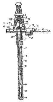
Turning now to the figures, Figure 1 shows a well during drilling operations.
A drilling
platform 2 is equipped with a derrick 4 that supports a hoist 6. Drilling of
oil and gas wells is
carried out by a string of drill pipes connected together by "tool" joints 7
so as to form a drillstring
8. The hoist 6 suspends a kelly 10 that is used to lower the drillstring 8
through rotary table 12.
Rotating table motor 11 may rotate rotary table 12 from the side as shown in
Figure 1, or may also
do so from above the rotary table, alternatively mounted on Kelly 10 (not
shown). Connected to the
lower end of the drillstring 8 is a drill bit 14. The bit 14 is rotated and
drilling accomplished by
rotating the drillstring 8, by use of a downhole motor near the drill bit, or
by both methods. Drilling
fluid, termed mud, is pumped by mud recirculation equipment 16 through supply
pipe 18, through
drilling kelly 10, and down through the drillstring 8 at high pressures and
volumes (e.g., 3000 p.s.i.
at flow rates of up to 1400 gallons per minute) to emerge through nozzles or
jets in the drill bit 14.
The mud then travels back up the hole via the annulus formed between the
exterior of the drillstring
8 and the borehole wa1120, through the blowout preventer 22, and into a mud
pit 24 on the surface.
On the surface, the drilling mud is cleaned and then recirculated by
recirculation equipment 16.
The drilling mud is used to cool the drill bit 14, to carry cuttings from the
base of the bore to the
surface, and to balance the hydrostatic pressure in the rock formations.
Downhole sensors 26 are coupled to an acoustic telemetry transmitter 28 that
transmits
telemetry (e.g., information-carryying) signals in the form of acoustic
vibrations in the tubing wall of
drillstring 8. An acoustic telemetry receiver 200 is coupled to the kelly 10
to receive transmitted
acoustic telemetry signals. One or more repeater modules 32 may be provided
along the drillstring
to receive and retransmit the acoustic telemetry signals. The repeater modules
32 include both an
acoustic telemetry receiver and an acoustic telemetry transmitter configured
similarly to receiver
200 and the transmitter 28.
Telemetry transmissions from either the transmitter 28 or the repeater modules
32 may
comprise data sent as it is collected ("continuous" or "real-time" data), data
stored and transmitted
after a delay ("buffered" or "historical" data), or a combination of both,
each transmitted at different
times during drilling operations. LWD data collected during actual drilling
may be collected at a
relatively high resolution (e.g., one sample for every six inches of
penetration), and saved locally in
memory (e.g., within the downhole sensor 26, the transmitter 28, or any of the
repeaters 32). This
high-resolution data may be needed in order to perform a meaningful analysis
of the downhole
formations. But because of the limited bandwidth of downhole telemetry
systems, the data may
have to be transmitted at a much lower resolution (e.g., one sample every four
feet). In at least
4
CA 02580691 2007-03-16
WO 2006/052319 PCT/US2005/032708
some embodiments the data may be saved at a higher resolution as described
above, and transmitted
to the surface at a later time when the tool is still downhole, but while
drilling is not taking place
(e.g., when a tool gets stuck or when the hole is being conditioned). This
historical transmission
may be at a sample resolution higher than the resolution normally used for
real-time data
transmission.
When drilling is not taking place, there generally is no real-time data being
transmitted.
During this time selected portions of saved data may be transmitted or
retransmitted to the surface.
Since this is not real-time data, the only time restriction on the
transmission is the time available
before drilling and real-time data transmission resume. Thus, for example, a
selected, one-hour
window of data saved in memory and collected at a resolution of one sample
every six inches may
be transmitted to the surface, even though it may take multiple hours to
transmit the data.
The data may be transmitted in chronological or reverse chronological order,
and may be
transmitted at any resolution desired. For example, all the data may be
transmitted for maximum
resolution, or every otlier sample may be transmitted for better but not
maximum resolution. The
resolution selected generally represents a trade-off between the time
available to retrieve the saved
data and the resolution needed to properly analyze the data. Also, any start
and stop point may be
selected within the memory where the data is saved (each location in memory
correlating to a
measured parameter sampled at a specific drilling time and depth).
The downhole sensor 26, transmitter 28 and repeaters 32 may be adapted to
acoustically
receive commands transmitted from the surface. These commands may control the
suspension of
real-time data collection and/or transmission, the selection of saved data,
the selection of the desired
resolution of data transmission, the initiation of saved data transmission,
the suspension of saved
data transmission, and the resumption of real-time data collection and/or
transmission.
As can be seen from Figure 1, the nature of drilling operations creates a
noisy environment.
Noise present during drilling operations may include the noise produced by the
drill bit 14, noise
from pumps such as those used by the mud recirculation equipment 16, and noise
from activities on
the drilling platform 2 to name just a few. Activities adjacent to the
drilling rig may also produce
noise, such as the operation of heavy equipment on the site and generators
providing electrical
power. Much of the noise described is produced at the surface of the drill
site. Sensors 40 may be
placed at various locations throughout the drill site as shown so as to detect
the "surface noise" near
the sources of noise. Such locations may include the derrick 4, the rotating
table motor 11, the
recirculation equipment 16, and the ground near the drilling platform 2. The
sensors may include,
for example, accelerometers mounted on the equipment, microphones place around
the site, and
geophones inserted into the ground. By placing the sensors 40 near each of the
noise sources, the
surface noise may be distinguished from the telemetry signal and drill bit
noise propagated along
5
CA 02580691 2007-03-16
WO 2006/052319 PCT/US2005/032708
the drillstring. The noise from each source thus detected may then be combined
and used as a noise
reference signal for an adaptive noise-canceling receiver within an acoustic
telemetry system.
Figure 2 illustrates an adaptive noise-canceling receiver 200 for a through-
drillstring
acoustic telemetry system constructed in accordance with at least some
embodiments. Noise is
detected by a plurality of sensors placed in proximity to a drilling rig
comprising a through-
drillstring acoustic telemetry system. The noise sensors may couple to the
receiver 200 using
electrical or optical cables. The noise sensors each may also comprise a radio
frequency antenna
that may be used to wirelessly couple the sensors to the receiver 200. As
shown in the embodiment
of Figure 2, each of the individual noise signals nl (t), n2 (t), and n3 (t)
are respectively coupled to
the input of adaptive transversal filters 202, 204, and 206. Each filter
output n1 (t), n2 W, and
n3 (t) represents an estimate by the corresponding filter of the contribution
of that noise source to
the actual noise n(t) that is present at the receiver 200 on drillstring
8(Figure 1). Each filter output
is coupled to an input of summing node 208, and the output of summing node 208
couples to
summing node 210 at one of its two inputs. The output of summing node 208 is
the estimated noise
n(t) and approximates the actual noise n(t). The input signal f(t) (comprising
the actual noise
n(t) plus the telemetry signal s(t) received by the receiver 200 on
drillstring 8) couples to
summing node 210 at its remaining input and combines with the negative of the
estimated noise
n(t), resulting in an estimated telemetry signal s(t). This is represented by
the equation:
s(t) = s(t) + n(t) - n(t) (1)
The estimated signal s(t) couples back as an input to each of the adaptive
transversal filters
202, 204 and 206. The estimated signal s(t) operates as an error measurement
that is used by each
of the adaptive transversal filters as a basis for reducing the error between
the estimated signal s(t)
and the actual signal s(t).
Equation (1) expresses the noise cancellation function of the acoustic
telemetry system, in
accordance with at least some embodiments. This function is illustrated in
greater detail in an
alteznative embodiment of the adaptive noise-canceling receiver 200 configured
as shown in Figure
3. An acoustic telemetry signal is generated by acoustic transmitter 310,
which couples to transfer
function 308. Acoustic transmitter 310 does not necessarily represent a single
physical transmitter
(such as telemetry transmitter 28 in Figure 1), but is representative of a
source for the original
acoustic telemetry signal s, (t) from a first telemetry transmitter. Likewise,
the transfer function
308 does not represent a single physical component of the system. The transfer
function 308
instead is representative of the distortion that the signal s1 (t) undergoes
when propagated through
6
CA 02580691 2007-03-16
WO 2006/052319 PCT/US2005/032708
the drillstring from downhole up to the surface. The signal that results from
the distortion
introduced by propagation of the signal sl (t) through the drillstring is
represented by acoustic
telemetry signal s2 (t).
Similarly, environmental noise around the drilling rig is represented in the
example of
Figure 3 as noise signal n, (t). Distortion resulting from the propagation of
the noise signal from
the source of nl (t) to the drillstring is represented by transfer function
304. The signal that results
from the distortion introduced by propagation of the noise nl (t) through the
environment
surrounding the drilling rig (e.g., the ground, and the rig itselfj is the
noise n(t). Signal s2(t) and
noise n(t) are combined at summing node 306. Summing node is also not a
physical summing
node within the system, but representative of the superposition of the two
signals s2 (t) and n(t),
and is shown in Figure 3 as the equation:
sZ (t) + n(t) (2)
The combined telemetry and noise signal is received by signal sensor 357,
which couples to
analog-to-digital converter (ADC) 358. ADC 358 digitizes the output of signal
sensor 357 to
produce the discrete, combined telemetry and noise signal s2(mT)+n(mT).
Likewise, the noise
signal nl (t) from sensor 302 is digitized by ADC 352 to produce discrete
noise signal ni (mT). In
the embodiment of Figure 3, the output of ADC 352 is coupled to adaptive
transversal filter 400,
which filters the discrete noise signal n1(mT) to produce discrete estimated
noise n(snT). The
output of ADC 358 and the output of the adaptive transversal filter 400 both
couple to the inputs of
summing node 355, the output of which couples to digital-to-analog converter
(DAC) 356 and
implements the equation:
s2(mT)= sz(nT)+n(nT)-n(mT) (3)
wherein mT represents a discrete sample yn with a sample period or T. The
discrete estimated
telemetry signal sZ (mT) may then be converted back to the continuous time
domain by DAC 356,
producing the continuous estimated telemetry signal s2 (t). The estimated
signal s2 (t) couples to
demodulator module 360, which may then generate a continuous estimated
telemetry signal sl (t)
from which the transmitted data may be demodulated. The generation of the
estimated signal sl (t)
may include filtering to account for distortion due to additional noise
sources (e.g., noise generated
downhole by the drill bit).
The discrete estimated telemetry signal sZ (nzT) also operates as an error
measure that is
used as a basis for reducing the error between the estimated telemetry signal
s2 (t) and the actual
7
CA 02580691 2007-03-16
WO 2006/052319 PCT/US2005/032708
telemetry signal s2(t). The output of the summing node 355 couples to adaptive
transversal filter
400, which uses the signal to adjust coefficients within the filter 400. The
adaptive transversal filter
400 may be implemented as a finite impulse response (FIR) filter, as
illustrated in Figure 4 in
accordance witli at least some embodiments of the invention. The discrete
noise signal nl (mT )
couples to a first discrete delay line 402, the output of which is the
discrete noise signal
nl ((m - 1)T) from the previous sample period. Likewise, the output of each
delay line is the
discrete noise signal from progressively older sample periods. Thus, the
output of discrete delay
line 406 (which is two samples delayed from discrete noise signal n1(mT)) is
nl ((m - 2)T), and
the output of discrete delay line 410 (which is j samples delayed) is n1((m -
j)T). Each delay
line couples to a corresponding multiplier (i.e., delay line 402 coupling to
multiplier 404, delay line
406 coupling to multiplier 408, and delay line 410 coupling to multiplier 412)
and the output of
each multiplier couples to summing node 414. Each of the delayed discrete
noise signals are
multiplied by a corresponding filter tap coefficient c (each tap coefficient
coupling to a
corresponding multiplier), and the resulting products are then summed to
together by summing
node 414 to produce the discrete estimated noise signal n(mT) at the output of
summing node 414.
As previously noted, the values of the filter tap coefficients c may be
adjusted
automatically based on the resulting output of the filter, such that the error
between the estimated
telemetry signal s2 (t) and the actual telemetry signal s2 (t) is reduced.
Figure 5 illustrates the
mechanism for adjusting a filter tap from the filter of Figure 4 constructed
in accordance with at
least some embodiments, which implements an automatic adjustment of a filter
tap coefficient.
Delay lines 402 and 410, multiplier 412 and summing node 414 all operate as
previously described.
The resulting discrete estimated noise yz(naT) at the output of summing node
414 couples to
summing node 355 (also shown in Figure 3) and is subtracted from the combined
discrete telemetry
and noise signal s2 (mT) + n(mT) to implement equation (3). The resulting
output of summing
node 355 is coupled to one of the inputs of multiplier 506, the other input
coupled to a
programmable adaptation coefficient 6. The output of the multiplier 506 is
coupled to one of the
two inputs to multiplier 504, the other input coupled to the output nl ((m -
j)T) of the delay line
410. The output of multiplier 504 is coupled to the input of accumulator 502,
the resulting product
of multiplier 504 added to a running total maintained in accumulator 502. The
output of
accumulator 502 is coupled to multiplier 412 and represents the filter tap
coefficient ci . The result
of this configuration is the coefficient adaptation equation:
cj ((m+1)T)=cj (mT)+A (mT)nl((m- j + 1)T) (4)
8
CA 02580691 2007-03-16
WO 2006/052319 PCT/US2005/032708
wherein mT represents a discrete sample m with a sample period or T.
Techniques for the
selection of values for the adaptation coefficients and of initial values for
the filter tap coefficients
are well know in digital signal processing by those skilled in the art and
thus are not discussed.
It is noted that a single filter may be used with a plurality of noise signals
summed together prior to
being presented to the input of the single filter. This and other noise
cancellation filter variations
will become apparent to one of skill in the art, and are intended to be
included within the scope of
the invention.
It is further noted that acoustic signaling may be performed in both
directions, uphole and
downhole. Repeaters may also be included along the drillstring to extend the
signaling range. In
accordance with at least some embodiments no more than one acoustic
transmitter will be operating
at any given time. The disclosed noise cancellation strategy is expected to be
most advantageous
for acoustic receivers located near the surface, as well as for acoustic
receivers "listening" to a-
transmitter located near the surface. However, improved system performance is
expected from the
use of noise cancellation by all the receivers in the system. It is further
noted that the disclosed
acoustic telemetry system can be employed for both LWD and MWD systems.
The above disclosure is meant to be illustrative of the principles and various
embodiments
of the present invention. Numerous variations and modifications will become
apparent to those
skilled in the art once the above disclosure is fully appreciated. It is
intended that the following
claims be interpreted to embrace all such variations and modifications.
9