Sélection de la langue

Search

Sommaire du brevet 2584046 

Énoncé de désistement de responsabilité concernant l'information provenant de tiers

Une partie des informations de ce site Web a été fournie par des sources externes. Le gouvernement du Canada n'assume aucune responsabilité concernant la précision, l'actualité ou la fiabilité des informations fournies par les sources externes. Les utilisateurs qui désirent employer cette information devraient consulter directement la source des informations. Le contenu fourni par les sources externes n'est pas assujetti aux exigences sur les langues officielles, la protection des renseignements personnels et l'accessibilité.

Disponibilité de l'Abrégé et des Revendications

L'apparition de différences dans le texte et l'image des Revendications et de l'Abrégé dépend du moment auquel le document est publié. Les textes des Revendications et de l'Abrégé sont affichés :

  • lorsque la demande peut être examinée par le public;
  • lorsque le brevet est émis (délivrance).
(12) Brevet: (11) CA 2584046
(54) Titre français: MONTAGE D'ELEMENT DE LAME DANS UN CHASSE-NEIGE
(54) Titre anglais: BLADE ELEMENT MOUNTING IN A SNOW PLOUGH
Statut: Réputé périmé
Données bibliographiques
(51) Classification internationale des brevets (CIB):
  • E01H 5/06 (2006.01)
(72) Inventeurs :
  • RUUSKA, MAUNO (Finlande)
(73) Titulaires :
  • AL-JON MANUFACTURING LLC (Etats-Unis d'Amérique)
(71) Demandeurs :
  • PATRIA VAMMAS OY (Finlande)
(74) Agent: BERESKIN & PARR LLP/S.E.N.C.R.L.,S.R.L.
(74) Co-agent:
(45) Délivré: 2014-08-19
(86) Date de dépôt PCT: 2005-10-11
(87) Mise à la disponibilité du public: 2006-04-20
Requête d'examen: 2010-10-08
Licence disponible: S.O.
(25) Langue des documents déposés: Anglais

Traité de coopération en matière de brevets (PCT): Oui
(86) Numéro de la demande PCT: PCT/FI2005/000434
(87) Numéro de publication internationale PCT: WO2006/040396
(85) Entrée nationale: 2007-04-10

(30) Données de priorité de la demande:
Numéro de la demande Pays / territoire Date
20041314 Finlande 2004-10-11

Abrégés

Abrégé français

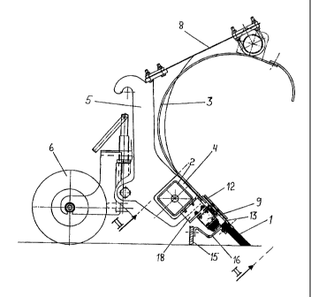
La présente invention décrit une suspension flexible d'un élément de coutre (1) d'un chasse-neige pourvu d'un corps (5), d'une lame (3) qui le prolonge, l'élément de coutre (1) entrant en contact avec la surface destinée à être déneigée, une inclinaison appropriée dans ce but, par exemple un angle d'attaque, étant agencée pour l'élément de coutre (1). L'élément de coutre (1) est installé pour reculer afin d'éviter un obstacle dans son angle d'attaque, moyennant quoi l'agencement de fixation de l'élément de coutre (1) présente un espace ouvert formé pour une plaque mobile (13) prolongeant l'élément de coutre, ladite plaque mobile étant agencée pour glisser dans ledit espace, et l'agencement comprend un organe à ressort (9) dont l'impact du ressort est agencé pour empêcher l'élément de coutre de reculer.


Abrégé anglais


Flexible suspension of colter element (1) of a snowplough furnished with a
body (5), a blade (3) as its extension, colter element (1) that gets in
contact with the surface to be ploughed, where for the colter element (1) a
tilt suited for the purpose is arranged, a.o. a cutting angle. Colter element
(1) is fitted to dodge an obstacle in its cutting angle by backing up, whereby
the fixing arrangement of colter element (1) has an open space formed for
moving plate (13) fitted as extension of the colter element, in which space
said moving plate is arranged to glide, and the arrangement includes a spring
organ (9) the spring impact of which is arranged to hinder the colter element
from backing up.

Revendications

Note : Les revendications sont présentées dans la langue officielle dans laquelle elles ont été soumises.


5
CLAIMS
1. A snowplough comprising:
a body;
a longitudinal colter;
a flexible suspension which suspends the colter to the body such that the
colter
is in contact with the surface to be ploughed and is set into a tilted cutting
angle;
a fixed blade which is an upwards extension of the colter;
a spring organ which is detachably attached to the colter and which backs up
the colter to enable the colter to dodge an obstacle by backing up against the
spring
organ;
a moving plate attached to and extending the colter toward the blade;
a cover plate in front of the fixed blade;
a mounting space formed between the fixed blade and the cover plate whereby
the moving plate is fitted to glide in the mounting space back up towards the
fixed
blade and then back down,
wherein the spring organ includes at least two U-shaped leaf springs,
each U-shaped leaf spring extending in a longitudinal direction along the
colter
and having a U-shape in a cross section parallel to the cutting angle,
one leg end of each U-shaped leaf spring being attached to the body and the
other leg end being attached to the colter such that the two U-shaped leaf
springs
together work essentially as straight-through mechanisms to back up the
colter.
2. A snowplough according to claim 1, wherein the cover plate is immobile
relative to the fixed blade and at least partly overlapping with the fixed
blade.
3. A snowplough according to claim 1, wherein the moving plate is at least
partly
overlapping with the fixed blade.

6
4. A snowplough according to claim 1,
further including an additional colter following behind the first-mentioned
colter and attached to the colter by a fixing device, and
wherein the flexible suspension suspends both said additional and first-
mentioned colters-in contact with the surface at the same time.

Description

Note : Les descriptions sont présentées dans la langue officielle dans laquelle elles ont été soumises.


CA 02584046 2007-04-10
WO 2006/040396 PCT/F12005/000434
1
BLADE ELEMENT MOUNTING IN A SNOW PLOUGH
The invention relates to a flexible mounting of the colter element of a
snowplough
furnished with a colter element that gets in contact with the surface to be
ploughed
including a blade as its extension, by which suspension for the colter element
a tilt, a.o. a
cutting angle, suited for the purpose is arranged. When the snowplough is
ploughing
uneven ground the colter must adjust to the roughness of ground. The flexible
colter
material is not enough alone, but the suspension of the colter must also be
flexible. The
need of flexibility grows with the width of the snowplough and the demands of
the
plough cleanliness.
In using flexible colters of polyurethane or rubber the load of colter against
the surface
to be ploughed must be small, but the colter must stay in same colter angle
during
flexing. The smallness of vertical force pressing colter is important in order
to minimize
wear and tear of the colter and to lengthen the life of the colter. Right
position keeps the
cutting of colter edge sharp without rounding the lower surface. Rounding of
colter
lower surface makes of the cutting colter edge rise from the ground and snow
getting
under the colter lifts the colter to glide on the snow layer. The result is
weakened
ploughing quality.
Backing of colter in its direction against a spring is known for instance from

publications DE 881200, GB 1060335, GB 784049. In these ones the colter
element is a
plate of large size, which must always be replaced as a whole, when
sufficiently worn
out. For the colter plate a quite long backward directed steering box portion
is arranged,
which keeps the colter in direction.
In using an additional colter, this colter must have same possibilities to
follow the
roughness of surface as the first colter.
Previously known is suspension of a colter, where the whole plough, for the
part of
" blade and colter, is divided into transverse elements, which are flexing
vertically on
levers or on flexible attachments. The disadvantage of this solution are the
relatively
heavy elements, which cause the colters a wearing load and hard strokes on
obstacles by

CA 02584046 2012-12-07
WO 2006/040396 PCT/F12005/000434
2
ploughing, because of the mass of elements. The moving of elements gives cause
to
discontinuity on blade surface and restricts blade forming. The circle curve
is almost the
only possible cross-cut of blade, if the motion is dimensioned to follow the
curve. The
direction of the evasive movement by means of lever mechanisms is in a
relatively great
angle in regard to the driving motion direction and thus disadvantageous.
Previously known is also a solution, where the mere colter is divided into
separately
suspended elements, which function simply steered by springs or separate
elements, as
GB 784049. There are wearing parts in the control mechanisms. Colters resting
merely
on springs have too great colter forces and often insufficient control, which
lead to rapid
wearing and blade bottom rounding. Known is also a solution, where the colter
is
suspended on springs of elastic rubber or of plastic.
The disadvantage of said solutions is weak control, whereby the colter wears
out into
wrong form. Another disadvantage appears bin speedy ploughing and the risk
connected
to overheating of spring material, and loss of spring material firmness due to
inside
frictions.
For suspension of an additional colter a further solution is known, where the
additional
colter is furnished with its own mechanisms both for the vertical and evasive
backward
motion of the colter. This is an expensive solution containing of many parts.
30

CA 02584046 2013-09-20
2a
According to the present invention there is provided a snowplough having a
body, a
longitudinal colter and a flexible suspension which suspends the colter to the
body
such that the colter is in contact with the surface to be ploughed and is set
into a titled
cutting angle. A fixed blade is provided and is an upward extension of the
colter. A
spring organ is detachably attached to the colter and backs up the colter to
enable the
colter to dodge an obstacle by backing up against the spring organ. A moving
plate is
attached to and extends the colter towards the blade. A cover plate is
provided in
front of the fixed blade and a mounting space is formed between the fixed
blade and
the cover plate, whereby the moving plate is fitted to glide in the mounting
space
back up towards the fixed blade and then back down.
The spring organ includes at least two U-shaped leaf springs. Each U-shaped
leaf
spring extends in a longitudinal direction along the colter and has a U-shape
in cross
section parallel to the cutting angle. One leg end of each U-shaped leaf
spring is
attached to the body and other leg end is attached to the colter such that the
two U-
shaped leaf springs work together essentially as straight-through mechanisms
to back
up the colter.
By means of the solution according to this invention most of the disturbances
appearing by the colter suspension are avoided and the suspension according to
this
invention is characterized in that to the spring organ a detachable colter
element is
attached, as extension to witch a plate attached to the colter element is
fitted, for
which plate an open space is formed between the attached colter and a covering
plate
at a distance from it, whereby said moving plate is fitted to glide in the
said open
space.
The advantage of the suspension according to this invention is each colter
element
and that to it possibly connected additional colter is built as a flexible
unit, which due
to its flexible attachment gets with its both colters in contact against the
surface. The
additional colter can be fixed to the attachments of the colter, whereby the
additional

CA 02584046 2012-12-07
WO 2006/040396 PCT/FI2005/000434
3
colter follows the colter motions. This approximate control is sufficient when
both
colters are flexible. The additional colter has a stabilizing extra impact on
the actual
colter. At the same time, the sequential colters give in the manner of the
boggie each
In the following the invention is disclosed with reference to the enclosed
drawing, where
Fig. 1 shows a snow plough viewed from the end.
Fig. 2 shows the sectional view 11-11 of the construction in figure 1.
Figure 1 shows a snowplough colter 1 furnished with body 5, height adjusting
support
wheel 6 and colter 1 including blade 3 as its extension. Colter 1 is of
flexible material
and is suspended from holders 8. There is in the body lower part a horizontal
beam 2
in which the colter elements 1 and lower edge 4 of blade 3 are fixed.
As extension of colter 1 there is a moving plate 13,which can move between the
surface
of fixed blade 3 and cover plate 12. Colter 1 is attached to moving plate 13
and to the
flexing lower end of spring organ 9. The upper end of spring organ 11 is
attached to
horizontal beam 2 by means of a distance piece 18.As spring there is a leaf
spring bent
The spring U-shape tends to open and by colter backing the U-shape tends to
narrow, in
other words fixing points 10 and 11 (figure 2) come closer to each other.
Figure 1 shows also an additional colter 15, which is by means of shaft 16,
bent of
spring steel, attached to colter 1.Thus the additional colter 15 flexes like
colter 1 in the
flexing direction of colter 1.
tend to open and press colter ldown. Stoppers 14 are connected to the end,
which
prevent colter 1 to get down only to a certain limit, even if spring 9 would
tend to
press the colter more dAward. By means of this stopper solution for the colter
initial

CA 02584046 2007-04-10
WO 2006/040396 PCT/F12005/000434
4
stress is achieved to prevent backing.. Thanks to the solution the springback
factor of the
spring remains almost unchangeable on a possible backing distance arranged for
the
colter. Between spring 9 lower fastening and colter 1 there can also be a
damping piece
17.
The colter element is attached at least between the ends of two leaf springs 9
bent into
U-shape and running in colter direction, while the other spring ends are
attached to the
plough body. U-shaped leaf springs function as rough straight-through
mechanisms. The
holding power in the direction of motion caused by bumpy surface is smallest
and at its
greatest in the direction that keeps the colter in right position. The
arrangement presses
the colter with a relatively small load against the surface being ploughed and
at the
same time keeps the colter steady in cutting position.
The advantage of prestressed spring suspension is the possibility of
relatively small
growth of the springback factor, while the spring route gets longer and at the
same time
for the colter an operating area is achieved at once after the limitation
without any
additional routes of motion, which would demand additional height for plough
lifting,
for instance in transporting position.
Advantageously the plough is formed of several colter elements side by side,
which have
separated flexing arrangements. Then only relatively small masses have to back
up on
hitting an obstacle. Even the ploughing result weakens only at the backed up
colter.
Blade portion 3 can be continuous along the whole plough width.

Dessin représentatif
Une figure unique qui représente un dessin illustrant l'invention.
États administratifs

Pour une meilleure compréhension de l'état de la demande ou brevet qui figure sur cette page, la rubrique Mise en garde , et les descriptions de Brevet , États administratifs , Taxes périodiques et Historique des paiements devraient être consultées.

États administratifs

Titre Date
Date de délivrance prévu 2014-08-19
(86) Date de dépôt PCT 2005-10-11
(87) Date de publication PCT 2006-04-20
(85) Entrée nationale 2007-04-10
Requête d'examen 2010-10-08
(45) Délivré 2014-08-19
Réputé périmé 2015-10-13

Historique d'abandonnement

Il n'y a pas d'historique d'abandonnement

Historique des paiements

Type de taxes Anniversaire Échéance Montant payé Date payée
Le dépôt d'une demande de brevet 400,00 $ 2007-04-10
Taxe de maintien en état - Demande - nouvelle loi 2 2007-10-11 100,00 $ 2007-04-10
Enregistrement de documents 100,00 $ 2007-07-10
Enregistrement de documents 100,00 $ 2008-09-12
Taxe de maintien en état - Demande - nouvelle loi 3 2008-10-14 100,00 $ 2008-09-19
Taxe de maintien en état - Demande - nouvelle loi 4 2009-10-13 100,00 $ 2009-09-18
Requête d'examen 800,00 $ 2010-10-08
Taxe de maintien en état - Demande - nouvelle loi 5 2010-10-12 200,00 $ 2010-10-08
Enregistrement de documents 100,00 $ 2010-11-09
Taxe de maintien en état - Demande - nouvelle loi 6 2011-10-11 200,00 $ 2011-09-29
Enregistrement de documents 100,00 $ 2011-11-24
Taxe de maintien en état - Demande - nouvelle loi 7 2012-10-11 200,00 $ 2012-10-01
Taxe de maintien en état - Demande - nouvelle loi 8 2013-10-11 200,00 $ 2013-10-10
Taxe finale 300,00 $ 2014-05-21
Titulaires au dossier

Les titulaires actuels et antérieures au dossier sont affichés en ordre alphabétique.

Titulaires actuels au dossier
AL-JON MANUFACTURING LLC
Titulaires antérieures au dossier
FORTBRAND SERVICES, INC.
HAGIE MANUFACTURING COMPANY
PATRIA VAMMAS OY
RUUSKA, MAUNO
Les propriétaires antérieurs qui ne figurent pas dans la liste des « Propriétaires au dossier » apparaîtront dans d'autres documents au dossier.
Documents

Pour visionner les fichiers sélectionnés, entrer le code reCAPTCHA :


Pour visualiser une image, cliquer sur un lien dans la colonne description du document. Pour télécharger l'image (les images), cliquer l'une ou plusieurs cases à cocher dans la première colonne et ensuite cliquer sur le bouton "Télécharger sélection en format PDF (archive Zip)" ou le bouton "Télécharger sélection (en un fichier PDF fusionné)".

Liste des documents de brevet publiés et non publiés sur la BDBC .

Si vous avez des difficultés à accéder au contenu, veuillez communiquer avec le Centre de services à la clientèle au 1-866-997-1936, ou envoyer un courriel au Centre de service à la clientèle de l'OPIC.


Description du
Document 
Date
(yyyy-mm-dd) 
Nombre de pages   Taille de l'image (Ko) 
Abrégé 2007-04-10 1 61
Revendications 2007-04-10 1 43
Dessins 2007-04-10 2 30
Description 2007-04-10 4 215
Dessins représentatifs 2007-06-08 1 10
Page couverture 2007-06-12 1 42
Description 2012-12-07 5 228
Revendications 2012-12-07 2 45
Dessins 2012-12-07 2 30
Description 2013-09-20 5 234
Revendications 2013-09-20 2 40
Page couverture 2014-07-25 2 46
Dessins représentatifs 2014-07-25 1 12
Cession 2007-07-10 2 60
PCT 2007-04-10 3 64
Cession 2007-04-10 3 78
Correspondance 2007-06-07 1 18
Cession 2008-09-12 3 70
Poursuite-Amendment 2010-10-08 1 42
Cession 2010-11-09 4 161
Cession 2011-11-24 5 211
Poursuite-Amendment 2012-06-08 3 120
Poursuite-Amendment 2012-12-07 15 564
Poursuite-Amendment 2013-03-20 2 72
Poursuite-Amendment 2013-09-20 7 180
Taxes 2013-10-10 1 33
Correspondance 2014-05-21 1 50