Sélection de la langue

Search

Sommaire du brevet 2584999 

Énoncé de désistement de responsabilité concernant l'information provenant de tiers

Une partie des informations de ce site Web a été fournie par des sources externes. Le gouvernement du Canada n'assume aucune responsabilité concernant la précision, l'actualité ou la fiabilité des informations fournies par les sources externes. Les utilisateurs qui désirent employer cette information devraient consulter directement la source des informations. Le contenu fourni par les sources externes n'est pas assujetti aux exigences sur les langues officielles, la protection des renseignements personnels et l'accessibilité.

Disponibilité de l'Abrégé et des Revendications

L'apparition de différences dans le texte et l'image des Revendications et de l'Abrégé dépend du moment auquel le document est publié. Les textes des Revendications et de l'Abrégé sont affichés :

  • lorsque la demande peut être examinée par le public;
  • lorsque le brevet est émis (délivrance).
(12) Brevet: (11) CA 2584999
(54) Titre français: CHARNIERE DE MOBILIER
(54) Titre anglais: FURNITURE HINGE
Statut: Réputé périmé
Données bibliographiques
(51) Classification internationale des brevets (CIB):
  • E05D 11/10 (2006.01)
  • E05F 1/12 (2006.01)
(72) Inventeurs :
  • LAUTENSCHLAGER, HORST (Allemagne)
(73) Titulaires :
  • LIBERTY HARDWARE MFG. CORP. (Etats-Unis d'Amérique)
(71) Demandeurs :
  • LIBERTY HARDWARE MFG. CORP. (Etats-Unis d'Amérique)
(74) Agent: GOWLING WLG (CANADA) LLP
(74) Co-agent:
(45) Délivré: 2011-11-22
(22) Date de dépôt: 2007-04-10
(41) Mise à la disponibilité du public: 2007-10-26
Requête d'examen: 2009-05-01
Licence disponible: S.O.
(25) Langue des documents déposés: Anglais

Traité de coopération en matière de brevets (PCT): Non

(30) Données de priorité de la demande:
Numéro de la demande Pays / territoire Date
10 2006 019 268.0 Allemagne 2006-04-26

Abrégés

Abrégé français

Il s'agit d'une charnière de mobilier pour une garniture de porte, qui comprend une cuvette encastrée, un axe de charnière, un bras porteur et un charnon contigu audit axe de charnière et fixant par pivotement le bras porteur à une partie intérieure de ladite cuvette encastrée. Au moins deux pattes de ressort sortent d'au moins deux spires et s'appuient contre une came, de chaque côté du charnon. Les pattes de ressort comprennent une première partie à l'extérieur de la cuvette encastrée, et une seconde partie, soutenue par la cuvette encastrée. Une balustre-ressort joint les pattes de ressort et elle est placée à l'extérieur de la cuvette encastrée. Une clavette d'arrêt, dépassant de la cuvette encastrée, maintient chaque patte de ressort, et une face de la cuvette supporte les spires.


Abrégé anglais

An example furniture hinge a door fitting including a recessed cup, a hinge pin, a carrier arm, and a hinge knuckle adjacent said hinge pin and pivotably attaching the carrier arm to an interior portion of said recessed cup. At least two spring legs extend from at least two spring coils and press against a cam on either side of the hinge knuckle. The spring legs have a first portion outside the recessed cup and a second portion supported by the recessed cup. A spring bow joins the spring legs and is positioned outside the recessed cup. A retaining pin extending from the recessed cup holds each of the spring legs, and a surface of said recessed cup supports the spring coils.

Revendications

Note : Les revendications sont présentées dans la langue officielle dans laquelle elles ont été soumises.


6
What is claimed is:


1. A furniture hinge, comprising:

a door fitting including a recessed cup;
a hinge pin;

a carrier arm;

a hinge knuckle adjacent said hinge pin and pivotably attaching said carrier
arm to an
interior portion of said recessed cup;

at least two first spring legs each extending from at least two spring coils
and pressing
against a cam on either side of said hinge knuckle, said at least two first
spring legs having a first
portion outside said recessed cup and a second portion supported by said
recessed cup;

at least two connecting legs extending from said at least two spring coils;
and

a spring bow joining said at least connecting legs and positioned outside said
recessed
cup, wherein a retaining pin extending from said recessed cup holds each of
said connecting legs,
and a surface of said recessed cup supports said at least two spring coils.

2. The furniture hinge of Claim 1, wherein each of said retaining pin
protruding from
opposing sides of said recessed cup are formed by ends of a common retaining
rod extending
through said recessed cup.

3. The furniture hinge of Claim 1, wherein said at least two connecting legs
extend from
opposing outer ends of said spring coil.


7

4. The furniture hinge of Claim 3, wherein said at least two connecting legs
extend from an
outer side of said at least two spring coils, said outer side located away
from said surface of said
recessed cup.

5. A furniture hinge, comprising:

a door fitting including a recessed cup;
a hinge pin;

a carrier arm;

a hinge knuckle adjacent said hinge pin and pivotably attaching said carrier
ann to an
interior portion of said recessed cup;

at least two spring legs each extending from at least two spring coils and
pressing against
a cam on either side of said hinge knuckle;

at least two connecting legs extending from said at least two spring coils;
and

a spring bow joining said at least two connecting legs and positioned outside
said
recessed cup, wherein said at least two connecting legs are laterally spaced
from said recessed
cup.

6. The furniture hinge of Claim 5, wherein said recessed cup extends further
from said at
least two spring coils than said at least two connecting legs.

7. The furniture hinge of Claim 5, including a retaining pin extending from
said recessed
cup that holds each of said connecting legs.


8


8. The furniture hinge of Claim 5, including a spring bow joining said at
least connecting
legs and positioned outside said recessed cup.


9. The furniture hinge of Claim 8, wherein said recessed cup extends further
from said at
least two spring coils than said spring bow.


10. The furniture hinge of Claim 5, wherein said at least two connecting legs
extend from
opposing outer ends of said spring coil.


11. The furniture hinge of Claim 10, wherein said at least two connecting legs
extend from an
outer side of said at least two spring coils, said outer side located away
from said surface of said
recessed cup.


12. A furniture hinge, comprising:

a fitting including a recessed cup mountable to at least one of a door or a
frame;
a hinge pin;

a carrier arm;

a hinge knuckle adjacent said hinge pin and pivotably attaching said carrier
arm to an
interior portion of said recessed cup;


9


at least two spring legs each extending from at least two spring coils and
pressing against

a cam on either side of said hinge knuckle, said at least two first spring
legs having a first portion
outside said recessed cup and a second portion supported by said recessed cup;

a retaining pin extending from said recessed cup;

at least two connecting legs each extending from said at least two spring
coils and
pressing against said retaining pin on either side of said recessed cup, said
at least two
connecting legs extending closer to a surface of said door or said frame than
said retaining pin.

13. The furniture hinge of Claim 12, including a spring bow joining said at
least connecting
legs and positioned outside said recessed cup.


14. The furniture hinge of Claim 12, wherein said at least two connecting legs
extend from
opposing outer ends of said spring coil.


15. The furniture hinge of Claim 14, wherein said at least two connecting legs
extend from an
outer side of said at least two spring coils, said outer side located away
from said surface of said
recessed cup.


Description

Note : Les descriptions sont présentées dans la langue officielle dans laquelle elles ont été soumises.


CA 02584999 2007-04-10

FURNITURE HINGE

This application claims priority to German Patent Application No. 10 2006
019 268.0 filed on April 26, 2006.
BACKGROUND OF THE INVENTION
This invention relates to a furniture hinge. More particularly, this invention
relates to a furniture hinge having a door fitting in the form of a recessed
cup with a
carrier arm pivotably mounted within the recessed cup, in which two spring
legs
extending from a coil spring outside the recessed cup and supported by the
recessed
cup, press against a cam on either side of a hinge knuckle.
Some known furniture hinges, such as the type described in U.S. Patent No.
5,617,612, accommodate two spring coils and two spring legs extending from the
spring coils on a common axis inside the recessed cup. A spring bow, supported
by
the inner surface of the recessed cup, joins the two opposing ends of the two
spring
coils. The recessed cup accommodates the entire spring. If not covered by a
cover
plate, the spring is accessible and visible from the inner side of the
furniture door.
The interior portion of the recessed cup accommodating the spring can become
dirty
and is difficult to clean. Further, the visible arrangement of the spring is
considered
aesthetically obtrusive.
Other known furniture hinges include the two spring coils on the non-visible
exterior of the recessed cup. Only the two spring legs that bear against the
cams on
the hinge knuckle of the carrier arm extend through openings into the interior
space
of the recessed cup. The two spring coils are accommodated and pivot at either
end
of a common pin that extends crosswise through the recessed cup. A separate
support leg extends from each spring coil and is supported at the recessed
cup. The
separate support leg transmits the force required for pre-tensioning of the
spring coil
against the recessed cup. Only the pin carrying and securing the spring coil
prevents
tipping the spring coil. As the internal diameter of the spring coil changes
as a
consequence of spring movement, exact placement of the spring coil on the
bearing
pin is difficult. Also, assembly and securing of the two spring parts is also
difficult.
1

h
CA 02584999 2007-04-10

It would be desirable to design a furniture hinge that is simple to assemble
and in which the spring components in their assembled state are retained
simply and
reliably in their predetermined position.

SUMMARY
An example furniture hinge a door fitting including a recessed cup, a hinge
pin, a carrier arm, and a hinge knuckle adjacent said hinge pin and pivotably
attaching the carrier arm to an interior portion of said recessed cup. At
least two
spring legs extend from at least two spring coils and press against a cam on
either
side of the hinge knuckle. The spring legs have a first portion outside the
recessed
cup and a second portion supported by the recessed cup. A spring bow joins the
spring legs and is positioned outside the recessed cup. A retaining pin
extending
from the recessed cup holds each of the spring legs, and a surface of said
recessed
cup supports the spring coils.

Another example furniture hinge includes two spring coils joined together by
a spring bow located outside the recessed cup. Each connecting leg extending
from
each spring coil of the spring bow engages a retaining pin extending from the
recessed cup. The two spring coils are supported at their outer ends by a
support
surface of the recessed cup.
BRIEF DESCRIPTION OF THE DRAWINGS
The various features and advantages of this disclosure will become apparent
to those skilled in the art from the following detailed description. The
drawings that
accompany the detailed description can be briefly described as follows:
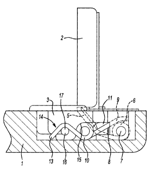
Figure 1 shows a cross-sectional side view of an example furniture hinge in a
closed position;

Figure 2 shows a front view of the example furniture hinge;
Figure 3 shows an example spring from the example furniture hinge.
DETAILED DESCRIPTION
The example furniture hinge shown in Figures 1 and 2 serves for the
pivotable attachment of a furniture door 1 to a piece of furniture. For
example, the
2


CA 02584999 2007-04-10

example furniture hinge pivotably attaches the furniture door 1 to a furniture
front
frame 2 of a piece of having a "face-frame" design.
The furniture hinge includes a door fitting that, in this example, is a
recessed
cup 3 attached to the furniture door 1 with screws securing a pair of
attachment ears
4 on the sides of the recessed cup 3.
A carrier arm 5 attaches and pivotably connects to the front frame 2 by a
hinge knuckle 6 with a hinge-pin axis 7 within the recessed cup 3. The carrier
arm 5
is formed from sheet-metal, for example.
The hinge knuckle 6 includes a pair of cams 8 form on opposing sides of the
hinge knuckle 6. A pair of spring legs 9, extending from a spring coil 10
located
externally to the recessed cup 3, are biased against each of the cams 8. The
spring
legs 9 extend from one of the spring coils 10 through an opening 11 to the
interior of
the recessed cup 3.
The spring legs 9 press against the cams 8 so that the furniture door 1 is
held
in either a closed position (Figure 1) or an open position.
The two spring coils 10 are generally aligned with one another and lie on
opposing sides of the recessed cup 3. The spring legs 9 pressing against the
cams 8
extend from the opposing inner ends of the aligned spring coils 10. The
opposing,
outer ends of the spring coils 10 include a pair of connecting legs 12 joined
by a
common connecting member 13 to form a spring bow 14.
The spring bow 14 lies outside the recessed cup 3. The spring coils 10
forming the spring bow 14 are supported in pretensioned condition with their
outer
sides each against a support surface 15 of the recessed cup 3.
A retaining pin 16 extending from the recessed cup 3 holds the connecting
legs 12 extending from each of the spring coils 10. The connecting legs 12 are
bent
such that the connecting member 13 of the spring bow 14 lies against the lower
exterior of the recessed cup 3. Each retaining pin 16 extends from opposite
sides of
the recessed cup 3 and aligns with one another. A retaining rod 17 passing
through
the recessed cup 3 forms the retaining pin 16.
Referring now to Figure 3 with continuing reference to Figures 1 and 2, A
spring component 20 comprises the spring coils 10, the spring legs 9, the
connecting
legs 12, the connecting member 13, and the spring bow 14. The spring leg 9 and
the
3

G I
CA 02584999 2007-04-10

supporting leg 12 each extend from the bottom side of the spring coils 10, the
side
away from the support surface 15.
Each of the two aligned spring coils 10, which are supported by the support
surface 15 without the use of any internal pin or the like in this example,
include
three complete spring turns. During assembly of the spring component, the
required
spring pretension is obtained when the connecting member 13 of the spring bow
14
is urged into the position shown in Figure 1. The spring component maintains
this
pretensioned position by introduction of the retaining rod 17, the two ends of
which
form the retaining pins 16 for the support leg 12.
The open interior of the recessed cup 3, which is visible from the inner side
of the door, is practically free of all obtrusive components. Only the ends of
the
spring legs 9 extend through the opening 11 into the interior and the
retaining rod 17
extends crosswise through the interior of the recessed cup 3.
The example furniture hinge 10 provides a particularly simple and
advantageous one-piece design for manufacturing and assembly. Further,
preponderate portions of the spring component 20 are outside the recessed cup
3 and
thus are not visible and not accessible from the inner side of door 1.
The example furniture hinge 10 includes the advantageous one-piece spring
component 20, combined with the advantages of the spring coils 10 being
located
outside the recessed cup 3.

The example furniture hinge 10 is advantageous in that the support by the
recessed cup 3 to provide spring pretensioning takes place, first, on the
outer ends of
the spring coil 10 and, second, by means of retaining pins 16 extending from
the
recessed cup 3.

In another example furniture hinge 10, the two retaining pins 16, extending
from opposite sides of the recessed cup 3 and aligned with one another,
consist of
the retaining rod 17 extending through the recessed cup 3. The connecting
member
13 and spring bow 14 connecting the two spring coils 10 presses against the
underside of the recessed cup 3 and the retaining rod 17 is positioned
crosswise into
the recessed cup 3 to support the connecting legs 12 of the spring bow 13 to
pretension the spring during assembly.
The preceding description is exemplary rather than limiting in nature.
4

L
CA 02584999 2007-04-10

Variations and modifications to the disclosed examples may become apparent to
those skilled in the art that do not necessarily depart from the essence of
this
disclosure. The scope of legal protection given to this disclosure can only be
determined by studying the following claims.

5

Dessin représentatif
Une figure unique qui représente un dessin illustrant l'invention.
États administratifs

Pour une meilleure compréhension de l'état de la demande ou brevet qui figure sur cette page, la rubrique Mise en garde , et les descriptions de Brevet , États administratifs , Taxes périodiques et Historique des paiements devraient être consultées.

États administratifs

Titre Date
Date de délivrance prévu 2011-11-22
(22) Dépôt 2007-04-10
(41) Mise à la disponibilité du public 2007-10-26
Requête d'examen 2009-05-01
(45) Délivré 2011-11-22
Réputé périmé 2019-04-10

Historique d'abandonnement

Il n'y a pas d'historique d'abandonnement

Historique des paiements

Type de taxes Anniversaire Échéance Montant payé Date payée
Enregistrement de documents 100,00 $ 2007-04-10
Le dépôt d'une demande de brevet 400,00 $ 2007-04-10
Taxe de maintien en état - Demande - nouvelle loi 2 2009-04-14 100,00 $ 2009-03-26
Requête d'examen 800,00 $ 2009-05-01
Taxe de maintien en état - Demande - nouvelle loi 3 2010-04-12 100,00 $ 2010-03-26
Taxe de maintien en état - Demande - nouvelle loi 4 2011-04-11 100,00 $ 2011-03-31
Taxe finale 300,00 $ 2011-09-07
Taxe de maintien en état - brevet - nouvelle loi 5 2012-04-10 200,00 $ 2012-03-21
Taxe de maintien en état - brevet - nouvelle loi 6 2013-04-10 200,00 $ 2013-03-21
Taxe de maintien en état - brevet - nouvelle loi 7 2014-04-10 200,00 $ 2014-03-20
Taxe de maintien en état - brevet - nouvelle loi 8 2015-04-10 200,00 $ 2015-03-17
Taxe de maintien en état - brevet - nouvelle loi 9 2016-04-11 200,00 $ 2016-03-15
Taxe de maintien en état - brevet - nouvelle loi 10 2017-04-10 250,00 $ 2017-03-16
Titulaires au dossier

Les titulaires actuels et antérieures au dossier sont affichés en ordre alphabétique.

Titulaires actuels au dossier
LIBERTY HARDWARE MFG. CORP.
Titulaires antérieures au dossier
LAUTENSCHLAGER, HORST
Les propriétaires antérieurs qui ne figurent pas dans la liste des « Propriétaires au dossier » apparaîtront dans d'autres documents au dossier.
Documents

Pour visionner les fichiers sélectionnés, entrer le code reCAPTCHA :


Pour visualiser une image, cliquer sur un lien dans la colonne description du document. Pour télécharger l'image (les images), cliquer l'une ou plusieurs cases à cocher dans la première colonne et ensuite cliquer sur le bouton "Télécharger sélection en format PDF (archive Zip)" ou le bouton "Télécharger sélection (en un fichier PDF fusionné)".

Liste des documents de brevet publiés et non publiés sur la BDBC .

Si vous avez des difficultés à accéder au contenu, veuillez communiquer avec le Centre de services à la clientèle au 1-866-997-1936, ou envoyer un courriel au Centre de service à la clientèle de l'OPIC.


Description du
Document 
Date
(yyyy-mm-dd) 
Nombre de pages   Taille de l'image (Ko) 
Abrégé 2007-04-10 1 17
Description 2007-04-10 5 209
Revendications 2007-04-10 1 35
Dessins 2007-04-10 2 26
Dessins représentatifs 2007-10-02 1 8
Page couverture 2007-10-15 1 36
Revendications 2011-05-10 4 107
Dessins représentatifs 2011-10-18 1 8
Page couverture 2011-10-18 1 36
Correspondance 2007-05-18 1 25
Cession 2007-04-10 3 81
Cession 2007-10-05 4 119
Poursuite-Amendment 2009-05-01 2 50
Correspondance 2011-09-07 2 49
Poursuite-Amendment 2010-12-01 2 60
Poursuite-Amendment 2011-05-10 6 189