Sélection de la langue

Search

Sommaire du brevet 2586269 

Énoncé de désistement de responsabilité concernant l'information provenant de tiers

Une partie des informations de ce site Web a été fournie par des sources externes. Le gouvernement du Canada n'assume aucune responsabilité concernant la précision, l'actualité ou la fiabilité des informations fournies par les sources externes. Les utilisateurs qui désirent employer cette information devraient consulter directement la source des informations. Le contenu fourni par les sources externes n'est pas assujetti aux exigences sur les langues officielles, la protection des renseignements personnels et l'accessibilité.

Disponibilité de l'Abrégé et des Revendications

L'apparition de différences dans le texte et l'image des Revendications et de l'Abrégé dépend du moment auquel le document est publié. Les textes des Revendications et de l'Abrégé sont affichés :

  • lorsque la demande peut être examinée par le public;
  • lorsque le brevet est émis (délivrance).
(12) Brevet: (11) CA 2586269
(54) Titre français: BOURRELET DE CALFEUTRAGE AVEC REVETEMENT PROTECTEUR LIBERABLE
(54) Titre anglais: WEATHERSTRIP WITH RELEASABLE PROTECTIVE COVERING
Statut: Octroyé
Données bibliographiques
(51) Classification internationale des brevets (CIB):
  • E06B 7/22 (2006.01)
  • B29C 65/08 (2006.01)
(72) Inventeurs :
  • DEMELLO, ALAN J. (Etats-Unis d'Amérique)
(73) Titulaires :
  • ULTRAFAB, INC. (Etats-Unis d'Amérique)
(71) Demandeurs :
  • ULTRAFAB, INC. (Etats-Unis d'Amérique)
(74) Agent: BORDEN LADNER GERVAIS LLP
(74) Co-agent:
(45) Délivré: 2015-03-31
(22) Date de dépôt: 2007-04-25
(41) Mise à la disponibilité du public: 2007-11-15
Requête d'examen: 2012-04-13
Licence disponible: S.O.
(25) Langue des documents déposés: Anglais

Traité de coopération en matière de brevets (PCT): Non

(30) Données de priorité de la demande:
Numéro de la demande Pays / territoire Date
60/800,390 Etats-Unis d'Amérique 2006-05-15

Abrégés

Abrégé français

Un coupe-froid à poils est pourvu dun fil de poil soudé par ultrasons à une bande de soutien à lintérieur dun canal défini par des brides, appelées dispositifs dorientation de poils, qui dirigent le poil perpendiculairement par rapport à la bande de soutien. Une pellicule sert de revêtement au poil et est fixée de manière libérable aux brides sur lextérieur de celles-ci. La pellicule de recouvrement peut comporter des perforations situées à proximité des brides près des extrémités supérieures des brides. Ou bien, une soudure par ultrasons faible du revêtement aux brides, comme celle réalisée au moyen dune énergie beaucoup plus faible que celle utilisée pour souder le poil et la bande de soutien ensemble, offre une fixation libérable pour le revêtement. Ce dernier protège le poil, comme au moment de linstallation dans un cadre, qui peut être peint une fois le coupe-froid installé. On peut libérer le revêtement en le retirant des brides du dispositif dorientation de poils après linstallation et la peinture.


Abrégé anglais

A pile weatherstrip has a pile of yarn ultrasonically welded to a backing strip inside a channel defined by flanges, called pile directors, which direct the pile perpendicularly with respect to the backing. A film provides a covering for the pile and is releasably attached to the flanges on the outside thereof. The covering film may have perforations therein which are located adjacent to the flanges near the upper ends of the flanges. Alternatively, a weak ultrasonic weld of the covering to the flanges, such as made at much lower energy than used to weld the pile and the backing together, provides a releasable attachment for the covering. The covering protects the pile, for example during installation in a frame which may be painted after the weatherstrip is installed. The covering can be released by being pulled off the pile director flanges after installation and painting.

Revendications

Note : Les revendications sont présentées dans la langue officielle dans laquelle elles ont été soumises.


- 6 -
CLAIMS:
1. In a weatherstrip having a sealing member on a backing in a channel
inside a pair of
flanges providing pile directors adjacent to the backing and extending
therefrom to top edges
thereof, the improvement comprising a covering of film around said member
releasably
attached along releasable edges of the film along the outer side of said pile
directors, said film
being disposed to cover said sealing member when attached and to substantially
entirely
expose said sealing member when released near the top of the pile directors;
wherein:
the releasable edges are structured to releasably attach the film the outer
side of the
pile directors; and
the releasable edges are located so at least substantially the entire film may
be entirely
separated from the weatherstrip by pulling off of the weatherstrip.
2. The weatherstrip according to of claim 1 wherein of the releasable edges
are formed
by perforations in said film.
3. The weatherstrip according to claim 1 wherein the releasable edges are
formed by a
weak ultrasonic weld, provided by energy much lower than ultrasonic energy
welding said
sealing member to said backing in said channel.
4. The weatherstrip according to claim 1 wherein said film is from 0.5 to
10 mils in
thickness.
5. The weatherstrip according to claim 1 wherein said film is of plastic or
textile
material.
6. The weatherstrip according to claim 5 wherein said material is selected
from the group
consisting of polyolefin, polyethylene, or polypropylene.

- 7 -
7. The weatherstrip according to claim 1 wherein said film has a color.
8. The weatherstrip according to claim 1 wherein said film is clear.
9. The weatherstrip of claim 1 wherein said film is attached to said pile
directors by one
of ultrasonic weld or adhesive.
10. A weatherstrip having a backing strip and a sealing member attached
along the
backing strip comprising:
a thin member covering said sealing member along said backing strip in which
said
thin member is releasably attached adjacent to the backing strip by means
enabling removal of
substantially all of said thin member from the weatherstrip to entirely expose
said sealing
member;
wherein said means is provided by a line of perforations along each side of
the sealing
member which extends near said backing strip adjacent to said backing strip.
11. The weatherstrip according to claim 10 wherein said means is provided
by a releasable
bond attaching said thin member to said backing strip along each said of the
sealing member
such that said sealing member is exposed adjacent to said backing strip.
12. The weatherstrip according to claim 10 wherein the backing strip has a
pair of flanges
extending upwardly therefrom adjacent thereto to top edges thereof between
which extends
said sealing member, and said thin member is releasably attached to the
flanges near the top
edges thereof.
13. A weatherseal comprising:
an elongated weatherseal base portion;
a pile portion;
a removable cover member;
a first tearable seam; and
a second tearable seam;

- 8 -
wherein:
the pile portion is mechanically connected to and extends from the weatherseal
base
portion;
the cover member includes an first elongated edge and a second elongated edge,
with
the first elongated edge being at least substantially parallel to the second
elongated edge;
the first tearable seam detachably attaches the first elongated edge of the
cover
member to the weatherseal base portion;
the second tearable seam detachably attaches the second elongated edge of the
cover
member to the weatherseal base portion;
the first and second tearable seams are located and/or oriented so that the
removable
cover member at least substantially covers the pile portion; and
the first and second tearable seams are located, sized, shaped and/or oriented
so that
the cover member is at least substantially completely separated from the
weatherseal base
portion after the first and second seams are torn by pulling off the cover
member.
14. The weatherseal of claim 13 wherein:
the first hand-tearable seam comprises perforations in the cover member; and
the second hand-tearable seam comprises perforations in the cover member.

Description

Note : Les descriptions sont présentées dans la langue officielle dans laquelle elles ont été soumises.


CA 02586269 2007-04-25

-2-
WEATHERSTRIP WITH RELEASABLE PROTECTIVE COVERING
Description
The present invention relates to weatherstripping and improves such
weatherstripping by facilitating protection of the sealing member thereof
during
installation, especially when the frame of the fenestration product (window,
door, etc.) in
which the weatherstrip is installed is painted in the area of the
weatherstripping.
The invention is especially adapted for protection of the pile providing the
sealing
member of weatherstrip in which the pile is attached to a backing strip having
a channel
on the inside of flanges constituting walls of the channel; such flanges
sometimes being
called pile directors. Such weatherstrips are described in the following
patents: Horton,
U.S. Patent Nos. 3,175,256 and 4,148,953 and Johnson, U.S. Patent Nos.
5,338,382,
5,807,451, and 5,817,390.
In accordance with the invention, the weatherstrips have a thin flexible film
covering the pile wherein the film is releasably attached to the outside of
the pile
directors. The releasable attachment may be via perforations in and along the
film
immediately above the upper ends of the pile directors, or with weak,
ultrasonic welds
which are made with much lower energy (and heating) than the welds attaching
the pile
to the backing. When installed as in a T-Slot of a frame, the covering of the
pile provided
by the film is readily released and removed after installation or painting.
Protective covering or masks, such as of adhesively backed material have been
used to protect carpets, thresholds, floorboards, gaskets and the like,
especially during
painting operations. See Elliott, U.S. Patent No. 6,210,466, 4/01; Headrick et
al.,
5,611,173, 3/97; Nauman, 5,489,459, 2/96; Cox et al., 5,421,936, 6/95;
Silvestre
5,260,097, 11/93; Miller, 5,242,712, 9/93; Ballejos, 5,109,793, 5/92 and
Figaro,
3,416,981, 12/68. Weatherstrips sometimes include fin material to facilitate
formation of
the seal provided by a sealing member, such as a yam pile. 'See Lind, U.S.
Patent No.
4,078,106, 3/78 and Boyce, U.S. Patent No. 4,035,984, 12/81. However, the
novel
functionality and advantageous attachment of a releasable or removable
covering, with
the aid of the pile directors of pile weatherstripping, is an important
contribution provided
by this invention.


CA 02586269 2007-04-25

-3-
In accordance with the presently preferred embodiment of the invention, a pile
weatherstrip has a pile of yarn ultrasonically welded to a backing strip
inside a channel
defined by flanges, called pile directors, which direct the pile
perpendicularly with
respect to the backing. A film covers the pile and is releasably attached to
the flanges on
the outside thereof. The film attachment may have perforations located along
the
outsides of the flanges adjacent the upper edges thereof. Alternatively, the
film may be
attached to the flanges by a weak ultrasonic weld made at much lower energy
than used
to weld the pile and the backing together. The cover protects the pile, for
example during
installation in a frame which may be painted after the weatherstrip is
installed, and the
cover can be released or removed by being pulled off the pile directors after
installation
and painting.
The foregoing and other features and advantages of the invention will become
more apparent from the following description and drawings, in which:
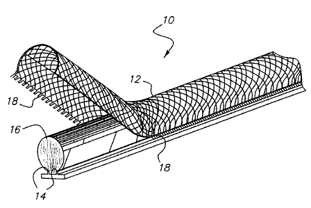
FIG. 1 is a perspective view showing an improved weatherstrip provided by the
invention installed in a frame of a window or door;

FIG. 2 is a perspective view illustrating two embodiments of the weatherstrip
provided by the invention; and

FIG. 3 is a perspective view illustrating the covering of a weatherstrip
provided
by the invention in the process of being released from the weatherstrip.
The drawings show a pile weatherseal which may be made in accordance with the
above referenced Horton and Johnson patents with a protective covering 12 over
the pile
16. The weatherseal is referred to as an ULTRA MASKTM weatherseal. The
covering 12,
as shown in FIG. 3, is a film or sheet of thin plastic material, similar to
that used in
providing fins inside or outside the pile in the above referenced Horton or
Johnson
patents, is ultrasonically welded to the outside of the pile directors
(flanges) 14. The film
-is looped over and covers the pile 16 to provide the releasable covering on
cladding 12.
After the covering or cladding 12 is looped around the pile sealing member 16
and ultrasonically welded to the outsides of the pile directors 14 around the
pile sealing
member 16, it can be perforated to provide lines of spaced perforations 18 in
the area of
pile directors just above the upper edges of pile directors 14 (see FIG. 2).
The completed


CA 02586269 2007-04-25

-4-
weatherstrip with its releasable covering 12 may be wound on a packing reel
for storage
or shipment.
Alternatively to the use of the perforations 18, a low energy weld 20 of the
film to
the outsides of the pile directors 14 may be provided to make the releasable
attachment
thereby eliminating the need for the perforation.
The weatherseal 10 may be installed in fenestration products (e.g., windows,
doors, etc.) in a T-Slot 22 of frame 24, as shown in FIG. 1, by hand, or with
an automated
insertion device, or online in a vinyl profile extruder used to make the
frame. The
covering or cladding 12 protects the sealing member 16 during fabrication
processes. A
primary application for the invention is to protect against is what is the
latest trend in
vinyl windows which to paint the profiles on certain surfaces to provide the
consumer
with more color options at a cost effective price. This process is lower cost
compared to
use of colored vinyl material itself.
Painting of fenestration products wherein pile weatherstripping was installed
required the installer to mask off the weatherstripping with special tape
before painting.
This was very labor intensive and time consuming. Sometimes the fabricator
just sprayed
paint over the weatherstripping which filled the pile with paint thereby
losing its sealing
properties.

Another problem fabricators faced is that the high air pressure used to propel
the
paint particles onto the surface of the fenestration product can actually
loosen fibers in
the pile and create a situation in which the fibers contaminate the painted
surface. These
problems in prior, conventional installations and painting are solved by this
invention.
The covering 12 such as solid, felted or spun polyolefin, like polypropylene,
may
be, as discussed above, for example, a film or sheet of plastic which may be 6
mil thick,
perforated just above the pile directors 14. A low energy weld 10 in the area
of the pile
director may be alternatively used. In either embodiment, covering 12 is
easily removed
as by being torn away, after being installed in a typical T-Slot retention
groove 22, which
is used in most vinyl or even aluminum extrusions.
The cladding or covering 12, is preferably ultrasonically welded, but could
also be
adhered by using conventional adhesives. More specifically, a polyolefin based
sheet or
film 12 ranging from .5 mil to 10 mil in thickness may be used for the
covering, but other


CA 02586269 2007-04-25

-5-
types of plastic or textile film could be used. Color of the film 12 is not
critical to the
actual manufacturing process, but a clear covering may be preferred by the end
user so
that the color of the underlying sealing members can be seen after
installation.

Dessin représentatif
Une figure unique qui représente un dessin illustrant l'invention.
États administratifs

Pour une meilleure compréhension de l'état de la demande ou brevet qui figure sur cette page, la rubrique Mise en garde , et les descriptions de Brevet , États administratifs , Taxes périodiques et Historique des paiements devraient être consultées.

États administratifs

Titre Date
Date de délivrance prévu 2015-03-31
(22) Dépôt 2007-04-25
(41) Mise à la disponibilité du public 2007-11-15
Requête d'examen 2012-04-13
(45) Délivré 2015-03-31

Historique d'abandonnement

Il n'y a pas d'historique d'abandonnement

Taxes périodiques

Dernier paiement au montant de 624,00 $ a été reçu le 2024-04-19


 Montants des taxes pour le maintien en état à venir

Description Date Montant
Prochain paiement si taxe générale 2025-04-25 624,00 $
Prochain paiement si taxe applicable aux petites entités 2025-04-25 253,00 $

Avis : Si le paiement en totalité n'a pas été reçu au plus tard à la date indiquée, une taxe supplémentaire peut être imposée, soit une des taxes suivantes :

  • taxe de rétablissement ;
  • taxe pour paiement en souffrance ; ou
  • taxe additionnelle pour le renversement d'une péremption réputée.

Les taxes sur les brevets sont ajustées au 1er janvier de chaque année. Les montants ci-dessus sont les montants actuels s'ils sont reçus au plus tard le 31 décembre de l'année en cours.
Veuillez vous référer à la page web des taxes sur les brevets de l'OPIC pour voir tous les montants actuels des taxes.

Historique des paiements

Type de taxes Anniversaire Échéance Montant payé Date payée
Enregistrement de documents 100,00 $ 2007-04-25
Le dépôt d'une demande de brevet 400,00 $ 2007-04-25
Taxe de maintien en état - Demande - nouvelle loi 2 2009-04-27 100,00 $ 2009-04-20
Taxe de maintien en état - Demande - nouvelle loi 3 2010-04-26 100,00 $ 2010-03-18
Taxe de maintien en état - Demande - nouvelle loi 4 2011-04-25 100,00 $ 2011-03-28
Requête d'examen 800,00 $ 2012-04-13
Taxe de maintien en état - Demande - nouvelle loi 5 2012-04-25 200,00 $ 2012-04-13
Taxe de maintien en état - Demande - nouvelle loi 6 2013-04-25 200,00 $ 2013-04-25
Taxe de maintien en état - Demande - nouvelle loi 7 2014-04-25 200,00 $ 2014-04-25
Taxe finale 300,00 $ 2015-01-12
Taxe de maintien en état - brevet - nouvelle loi 8 2015-04-27 200,00 $ 2015-04-01
Taxe de maintien en état - brevet - nouvelle loi 9 2016-04-25 400,00 $ 2016-05-02
Taxe de maintien en état - brevet - nouvelle loi 10 2017-04-25 450,00 $ 2017-05-01
Taxe de maintien en état - brevet - nouvelle loi 11 2018-04-25 250,00 $ 2018-04-23
Taxe de maintien en état - brevet - nouvelle loi 12 2019-04-25 450,00 $ 2019-04-26
Taxe de maintien en état - brevet - nouvelle loi 13 2020-04-27 250,00 $ 2020-04-17
Taxe de maintien en état - brevet - nouvelle loi 14 2021-04-26 255,00 $ 2021-04-16
Taxe de maintien en état - brevet - nouvelle loi 15 2022-04-25 458,08 $ 2022-04-15
Taxe de maintien en état - brevet - nouvelle loi 16 2023-04-25 473,65 $ 2023-04-21
Taxe de maintien en état - brevet - nouvelle loi 17 2024-04-25 624,00 $ 2024-04-19
Titulaires au dossier

Les titulaires actuels et antérieures au dossier sont affichés en ordre alphabétique.

Titulaires actuels au dossier
ULTRAFAB, INC.
Titulaires antérieures au dossier
DEMELLO, ALAN J.
Les propriétaires antérieurs qui ne figurent pas dans la liste des « Propriétaires au dossier » apparaîtront dans d'autres documents au dossier.
Documents

Pour visionner les fichiers sélectionnés, entrer le code reCAPTCHA :


Pour visualiser une image, cliquer sur un lien dans la colonne description du document. Pour télécharger l'image (les images), cliquer l'une ou plusieurs cases à cocher dans la première colonne et ensuite cliquer sur le bouton "Télécharger sélection en format PDF (archive Zip)" ou le bouton "Télécharger sélection (en un fichier PDF fusionné)".

Liste des documents de brevet publiés et non publiés sur la BDBC .

Si vous avez des difficultés à accéder au contenu, veuillez communiquer avec le Centre de services à la clientèle au 1-866-997-1936, ou envoyer un courriel au Centre de service à la clientèle de l'OPIC.


Description du
Document 
Date
(yyyy-mm-dd) 
Nombre de pages   Taille de l'image (Ko) 
Abrégé 2007-04-25 1 22
Description 2007-04-25 4 171
Revendications 2007-04-25 1 25
Dessins 2007-04-25 2 35
Dessins représentatifs 2007-10-19 1 22
Page couverture 2007-11-05 1 54
Page couverture 2015-02-26 1 54
Revendications 2014-05-14 3 97
Cession 2007-04-25 8 281
Poursuite-Amendment 2012-04-13 1 28
Poursuite-Amendment 2013-04-22 2 56
Correspondance 2013-09-19 1 13
Poursuite-Amendment 2013-11-14 2 55
Taxes 2014-04-25 1 33
Poursuite-Amendment 2014-05-14 5 164
Correspondance 2015-01-12 1 36