Note : Les descriptions sont présentées dans la langue officielle dans laquelle elles ont été soumises.
CA 02590021 2007-05-23
- Page l -
ABSTRACT
APPARATUS FOR RE-ENTERING AN ABANDONED WELL
This invention is in the field of oil and gas wells and in particular an
apparatus for
installation when abandoning a well that will safely allow re-entry into the
abandoned
well.
BACKGROUND
Oil and gas wells have a finite productive life. Once all economically
recoverable
product has been removed from the well, the well is abandoned. Typically such
abandonment involves cutting off the well casing below the ground surface,
sealing the
well, and then covering the sealed well with soil, effectively burying the top
of the well.
A typical well will have a production casing extending down from the surface
to the
production zone where oil or gas is present. At the surface the production
casing is
located inside a surface casing that has a diameter larger than the production
casing. The
surface casing extends downward from the surfaee into the ground to protect
the upper
portion of the production casing.
CA 02590021 2007-05-23
- Page 2 -
During abandonment the surface casing will be cut down to a level below ground
level,
and the production casing will be cut down to a level below the top of the
surface casing.
A steel production plate will be fitted inside the top of the production
casing and welded
to the production casing to seal the casing. A surface plate will be fitted
inside the top of
the surface casing above the production plate and welded in place to seal the
surface
casing.
It is at times required or desirable to re-enter abandoned wells to inspect
same or
sometimes to re-work the well when the economics of recovery change, or when
new
technologies become available that may make it economical to operate the well
again,
Such re-entry can be hazardous as there is no provision to allow an operator
to determine
whether pressure has built up inside one or both of the casings, and so the
sealing plates
must be drilled to determine what is present in the sealed casings. The
drilling tool must
be housed inside a pressure control apparatus to control any pressurized gases
that may
be present under the plates. The shank of a drill bit will extend through a
packing or like
sealing element in the pressure control apparatus such that when the plate is
pierced any
pressurized gases that may be present are contained. Channels and caps on the
pressure
control apparatus allow the gases to be directed to a vent or containment
vessel.
To re-enter a well it i.s typically required to weld the pressure control
apparatus on to the
surface plate. It is generally not possible or practical to determine the
extent of any
CA 02590021 2007-05-23
- Page 3 -
corrosion or like weaknesses that might be present in the casings or sealing
plates, and
the intense heat of welding may rupture same and cause a fire or other injury.
SUMMARY OF THE INVENTION
It is an object of the present invention to provide a method and apparatus for
allowing re-
entry into an abandoned oil or gas well that overcomes problems in the prior
art.
The invention comprises a drill guide tube where the bottom end of the tube is
welded to
a production plate that has been welded into place at the top end of a
production casing.
A surface plate for sealing the surface casing has a hole in the center of it
that is
configured so that the tube extends upward from the production plate through
the hole
such that the upper end of the tube is above the surface plate. The surface
plate is welded
to the surface casing and the tube to seal the surface casing.
The tube has a vent hole extending through the wall of the tube below the
surface plate
and above the production plate, and an internal plug is welded or machined
into the tube
so as to block the tube at a location above the vent and below the top end of
the tube.
The top end of the tube is threaded to allow a pressure control apparatus to
be secured to
the tube without welding. A greased cap is threaded into the top end of the
tube and
sealed with a rubber ring. Conveniently a marker flag, or ribbon or both can
be attached
CA 02590021 2007-05-23
-Page4-
to the top of the tube to facilitate locating the buried abandoned well.
When it is desired to re-enter the well, the cap is removed from the top end
of the tube,
and the pressure control apparatus is secured to the threads in the tube with
a drilling tool
installed. The internal plug is drilled out such that gases from the surface
casing can pass
through the vent and up the tube through the plug to the top end of the tube
to be directed
as desired. Once any pressure in the surface casing has been bled off, the
drill is pu,shed
through to the bottom of the tube and the production plate is drilled out, and
any
pressurized gases in the pnoduction casing can then pass up the central
channel to the top
end of the tube to be directed as desired.
Thus any pressurized gaces in the well can be bled off, and the nature of the
gases can be
determined without any welding. All required welding takes place during the
initial well
abandonment when the condition of the casings is readily visible, and before
corrosion
and the like can affect the casings.
CA 02590021 2007-05-23
-Page5-
DESCRIPTION OF THE DRAWINGS
While the invention is claimed in the concluding portions hereof, preferred
embodiments
are provided in the accompanying detailed description which may be best
understood in
conjunction with the accompanying diagrams where like parts in each of the
several
diagrams are labeled with like numbers, and where:
Fig. I is a schematic sectional side view of the drill guide tube of an
embodiment of
the present invention;
Fig. 2 is a top view of the surface plate for use with the embodiment of Fig.
1;
Fig. 3 is a schematic sectional side view of the apparatus of Figs. 1 and 2
installed in
an abandoned well;
Fig. 4 is a schematic sectional side view of a pressure control apparatus and
drill set up
to re-enter the abandoned well on which the apparatus of Fig. 3 is installed.
DETAILED DESCRIPTION OF THE ILLUSTRATED EMBODIMENTS
Figs. 1- 3 illustrate the operation of an embodiment of the well re-entry
apparatus I of
CA 02590021 2007-05-23
-Page6-
present invention. The apparatus I comprises, as seen in Fig.l, a drill guide
tube 3 with a
top end 3A and a bottoni end 3B. At a middle portion of the tube 3 a vent hole
5 extends
through the wall 7 of the tube to the central passage 9 of the tube 3. An
intemal plug 11
is located in the central passage 9 of the tube 3 to block the central passage
9 above the
vent hole 5 and below the top end 3A of the tube 3. The top end 3A of the tube
3 is
threaded and configured such that a pressure control apparatus can be adapted
to be
secured to the top end 3A of the tube 3 without welding. A threaded cap 13 is
threaded
onto the top end 3A of the tube 3 and sealed with a ntbber ring or the like to
keep to
prevent water, soil, and the like from entering the central passage 9 of the
tube 3 and to
protect the threads 12 on the top end 3A of the tube 3. The threads 12 can be
inside the
central passage 9 or on the outside of the tube 3, or both. Typically the cap
13 will be
greased to prevent it from corroding onto the threads of the tube 3 and to
facilitate
removal if and when re-entry is desired.
The tube 3 has a relatively thick wall 7 to reduce the risk that corrosion or
the like might
cause leak through the wall 7. Similarly the internal plug 11 is relatively
thick as well,
with a thickness about the same as that of the casing wall. The drill guide
tube 3 will
typically be machined from a steel cylinder to provide the required wall
thickness as well
as the threads, central passage, plug, and the like.
The apparatus 1 further comprises a sutface plate 21 as illustrated ui Fig. 2
for sealing the
CA 02590021 2007-05-23
-Page7-
surface casing of an abandoned well. The surface plate 21 has an outside
diameter
selected to fit snugly inside the surface casing such that same can be welded
to the
surface casing to seal the surface casing. The surface plate 21 also defines a
guide hole
23 in the middle thereof with a diamet.er selected such that the drill guide
tube 3 can slide
through the guide hole 23 and then welded to the surface plate to complete
sealing of the
surface casing as described below.
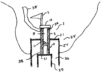
Fig. 3 illustrates the well re-entry apparatus 1 installed in an abandoned
well 25
comprising a surface casing 27 and a production casing 29. The soil at the top
of the well
25 has been excavated and the surface casing 27 and production casing 29 have
been cut
off below ground level, with the top of the production casing 29 below the top
of the
surface casing 27. A production plate 31 has been welded into the production
casing 29
to seal the production casing 29.
The bottom end 3B of the drill guide tube 3 is then tacked to the top surface
of the
production plate 31. The surface plate 21 is moved down over the tube 3 so the
tube 3
slides up through the guide hole 23. The fit of the surface plate 21 in the
surface casing
27 is checked and any adjustments are made. The surface casing 27 is then
removed.
The bottom end 3B of the tube 3 is welded to the production plate 31, and the
surface
plate 21 is moved down over the tube 3 again and welded into the surface
casing 27.
CA 02590021 2007-05-23
-Page8-
When installed as illustrated the vent hole 5 is located below the surface
plate 21 and
above the production plate 31 such that gases from the well annulus 30 between
the
outside of the production casing 29 and the inside of the surface casing 27
can enter the
cent.ral passage 9 of the tube 3.
The cap 13 is greased and installed on the threaded top end 3A of the tube 3
to seal the
tube 3. A flag stick 33, marker ribbon 35, or like aid to locating the well
may be
conveniently attached to the upper portion of the tube 3 extending above the
surface plate
21. Excavated soil can now be moved back to cover the abandoned well.
It is to be noted that with the configuration of the apparatus 1 the well is
sealed by solid
welded members, and failure of the threaded cap 13 will not release any gases
from the
well.
To re-enter the abandoned well 25 at a later date the cap 13 is removed from
the top end
3A of the tube 3 and a pressure control apparatus 41, as illustrated in Fig.
4, comprising
packing seals 43 or the like and with a drilling too145 installed, is secured
to the threaded
top end 3A of the tube. The internal plug 1 L is drilled out with the drill
bit 47 such that
gases from the well annulus 30 between the outside of the production casing 29
and the
inside of the surface casing 27 can pass through the vent hole 5 and up the
central passage
9 through the drilled out interaal plug 11 to the top end 3A of the tube 3 to
be directed
CA 02590021 2007-05-23
- Page 9 -
through conduits 49 connected to the pressure control apparatus 41 as desired.
Once any prtssure in the annulus 30 has been bled off, the drill bit 47 is
pushed through
to the bottom end 3B of the tube 3 and the production plate 31 is drilled out,
and any
pressurized gases in the prodtiction casing 29 can then pass up the central
channel 9 to the
top end 3A of the tube 3 to the pressure control apparatus 41 to be directed
as desired.
The present invention thus allows any pressurized gases in the well to be bled
off, and the
nature of the gases determined without any welding in the vicinity of the
well.
The foregoing is considered as illustrative only of the principles of the
invention.
Further, since numerous changes and modifications will readily occur to those
skilled in
the art, it is not desired to limit the invention to the exact construction
and operation
shown and described, and accordingly, all such suitable changes or
modifcations in
structure or operation which may be resorted to are intended to fall within
the scope of
the claimed invention.