Note : Les descriptions sont présentées dans la langue officielle dans laquelle elles ont été soumises.
CA 02594078 2007-07-18
CONTAINER HOLDER
BACKGROtTND OF THE INVENTION
1. Field of the Invention
[0001] The present invention relates to a holder for use in supporting a
container
or a bottle, in which the container can be fixed thereon upside down, for ease
of
completely using the liquid in the container.
2. The Prior Arts
[0002] Generally, viscous liquid, such as skin care lotions and shampoos,
stored
in a container or a bottle is not easy to flow out of the container due to
their viscosity.
When the liquid will be used up, the container should be put upside down for a
period
of time to wait the residual liquid flowing out of the container for use.
Therefore, in
general, users simply close a mouth of the container with a cap and then put
the
container on a plane surface in an inverted manner to let the residual liquid
flow out to
the mouth of the container. Then, the liquid can be easily extracted out for
use upon
opening the cap.
[0003] However, because some container caps were designed to have screw
threads or a straw, there still have the following problems when using the
above-mentioned method.
[0004] (1) If the quantity of the residual liquid is greater than the cap
capacity,
the liquid may overflow from the cap, thereby causing the waste of the liquid.
[0005] (2) The liquid which accumulates in the screw threads is not easy to be
effectively extracted out for use.
[0006) (3) Moreover, the cap with a straw generally has less capacity to
collect
the liquid, and the design of the straw may block the liquid from extracting
out.
l
CA 02594078 2007-07-18
[0007] (4) Also, owing that a top surface of some caps is designed to be not a
planar surface, it is hard for these containers to be stood on a plane surface
in an
inverted manner. Therefore, a supporting device may be required to hold the
containers to prevent them from falling down.
[0008] Thus, it is desired to provide a container holder for holding a
container in
an inverted manner for case of completely using the liquid in the container.
SUMMARY OF THE INVENTION
prn00c~] A l.ior~4i~~n f 4~n n~rnn
rncnnt '4i~n io to r~rwiAa a vontainer
~v ~1 prlllary vvJ~~Llvli vl ul~.= pl:J\:11l,lv~.l,L,võ J tJ,V1,1V
holder which can securely hold a container in an inverted manner and thus let
the
liquid flow out of the container completely, so that the liquid in the
container can be
completely used up.
[0010] In order to achieve the above objective, a container holder in
accordance
with the present invention includes a plate body, a base provided at a bottom
end of
the plate body, and a supporting member extended from a surface of the plate
body
and located above a spaced-apart distance from the base. The supporting member
is a
U-shaped sheet, and two supporting pieces of the U-shaped supporting member
are
parallel to each other and a space is defined between the two supporting
pieces. The
supporting member can hold a container in an inverted manner, and a liquid
collector
is placed at the base for collecting the liquid flowing out of the container.
[0011] Accordingly, in accordance with the present invention, the liquid in
the
container can timely and completely flow out for use. The waste of the liquid
can be
reduced and the cost can be effectively saved. Besides, users do not need to
handhold
the container in an inverted manner for a period of time to wait the liquid
flowing out
of the container when in use.
BRIEF DESCRIPTION OF THE DRAWINGS
2
CA 02594078 2007-07-18
[0012] The present invention will be apparent to those skilled in the art by
reading the following detailed description of the preferred embodiments
thereof, with
reference to the attached drawings, in which:
[0013] Fig. 1 is a perspective view showing a container holder in accordance
with a preferred embodiment of the present invention;
[0014] Fig. 2 is a schematic view showing that a container is fixed on the
container holder of the present invention; and
[0015] Fig. 3 is a perspective view showing a container holder in accordance
with another preferred embodiment of the present invention.
DETAILED DESCRIPTION OF THE PREFERRED EMBODIMENT
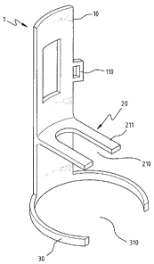
[0016] With reference to Fig.1, a container holder 1 in accordance with a
preferred embodiment of the present invention comprises a plate body 10, a
supporting member 20, and a base 30.
[0017] The plate body 10 is of strip-shaped with a transverse arc, and the
base 30
is provided at a bottom end of the plate body 10 for stably standing on a
plane surface.
In this embodiment, the base 30 has two arc members which extends in
transverse
from both sides of the bottom end of the plate body 10, respectively, and
define an
opening 310 at a center of the base 30 for placing a liquid collector 50 (see
Fig. 2), so
that the liquid flowing out of the container 40 can be collected in the liquid
collector
50. Moreover, the base 30 is made of the materials with high density, so that
the
container holder 1 can be stably placed on a plane surface without failing
down.
[0018] The supporting member 20 is a U-shaped sheet, which is extended from a
surface of the plate body 10 and located above a spaced-apart distance from
the base
30 for allowing the liquid collector 50 to place therebetween. Furthermore,
two
supporting pieces 211 of the U-shaped supporting member 20 are parallel to
each
3
CA 02594078 2007-07-18
other, and a space 210 is defined between the two supporting pieces 211. The
shoulder
of the container 40 can be held by the supporting pieces 211, and the head of
the
container 40 can pass through the space 210 of the supporting member 20.
Accordingly, the container 40 can be supported on the container holder 1.
[0019] Besides, a clamp 110 is provided at a side of the plate body 10 above
the
supporting membcr 20. Referring to Fig. 2, an elastic band 120 in combination
with
the clamp 10 is used to securely fix the container 40 on the container holder
1.
[0020] With reference to Fig. 1 and Fig. 2, the length of the plate body 10 is
defined according to the length of the container 40, so that the container 40
can be
securely fixed on the container holder 1. But the spaced-apart distance
between the
supporting member 20 and the base 30 just need to be properly defined for
allowing
the liquid collector 50 to place therebetween, wherein the liquid collector 50
can not
contact with the supporting member 20.
[0021] Please refer to Fig. 2, which shows a container is held on the
container
holder in accordance with the preferred embodiment of the present invention.
In Fig. 2,
the container 40 is placed on the container holder 1 in an inverted manner.
The two
supporting pieces 211 hold the shoulder of the container 40 and the head of
the
container 40 passes through the space 210 of the supporting member 20. The
liquid
collector 50 is placed below the head of the container 40 for collecting the
liquid
flowing out of the container 40. Also, the elastic band 120 fixes the
container 40 and
clamps with the clamp 110 (not shown in Figures), so that the container 40 can
be
securely fixed on the container holder 1.
[0022] Please refer to Fig. 3, which shows a container holder 1 in accordance
with another preferred embodiment of the present invention. The supporting
member
20 has an annular piece 211 and a central hole 220 defined on the annular
piece 211.
4
CA 02594078 2007-07-18
The container 40 can be placed on the supporting member 20 in an inverted
manner,
in which the shoulder of the container 40 is held by the annular piece 211 and
the
head of the container 40 passes through the central hole 220.
[0023] In brief, the present invention can securely hold a container in an
inverted
manner, so that the liquid in the container 40 can timely and completely flow
out for
use. Therefore, the waste of the liquid can be reduced and the cost can be
effectively
saved.
[0024] Although the present invention has been described with reference to the
preferred embodiments thereof, it is apparent to those skilled in the art that
a variety
of modifications and changes may be made without departing from the scope of
the
present invention which is intended to be defined by the appended claims.