Note : Les descriptions sont présentées dans la langue officielle dans laquelle elles ont été soumises.
CA 02594755 2009-11-05
1
FUEL CELL STACKS AND METHODS FOR CONTROLLING FUEL GAS FLOW TO
DIFFERENT SECTIONS OF FUEL CELL STACKS
Background of the Invention
A conventional hydrogen Polymer Electrolyte Membrane (PEM)
fuel cell configuration is depicted herein in Figure 1. In this
conventional configuration, the required number of single cells is
stacked and the gas supply to each single cell is connected in
parallel. Fuel and air required for the electrochemical reaction
are fed at the appropriate rate via common manifolds. The
direction of the gas flow is arbitrary and is shown as falling
arrows in Figure 1. Fuel gas supply to each of the individual
cells from the manifold at the top of the stack is essentially
equal. Similarly, the exhaust gas is collected and removed from
the stack via the outlet manifold at the bottom of the stack.
Thus, in the conventional fuel cell configuration shown in Figure
1, the supply gas flow follows in parallel flow paths in identical
flow directions and at uniform flow rates through each of the
individual cells.
Hydrogen fuel gas flow is adjusted to correspond to an anode
stoichiometry of X = 1.1. That is, preferably 20% excess of the
stoichiometric hydrogen consumption will be supplied in order for
the fuel cell to operate satisfactorily. The exhaust hydrogen
flow ensures complete purging of the cell. A greater excess of gas
affects the psychometric balance and may lead to undesirable
hydration of the PEM causing cell malfunction.
In certain situations, particularly where hydrogen produced
by electrolysis is not feasible or not available in sufficient
CA 02594755 2007-07-12
WO 2006/077477 PCT/IB2006/000057
2
quantity or reasonable cost, it is of interest to supply fuel
cells with degraded hydrogen supplies such as that provided
by reforming processes wherein carbon reacts with steam at
elevated temperatures to produce a mixture of CO and H2 or cracked
ammonia. It is thus desirable to obtain reformer fuels or gases
for electrochemical fuel cells via catalytic reforming of
hydrogen-rich fuels from the copious supply of carbon available as
organic refuse or other sources such as low grade petroleum
deposits including, but not limited to oil-shale, oil sand,
gilsonite and coal. Both fossil fuels, such as natural gas, petrol
or heating oil and biogenic/regenerative fuels, such as wood,
alcohol or rapeseed oil, can be used in this process. Methods are
known for producing a CO-H2 mixture from organic material. Such
methods are adaptable to, for example, carbon deposits from
petroleum coke or from coal deposits for conversion into a CO-H2
mixture. This mixture can then be burnt in conventional furnaces
or used as a reformer gas 'source of hydrogen for direct
electrochemical conversion in fuel cells. In cases where 100%
of the hydrogen gas supply is replaced by reformer gas
containing 75% hydrogen and 25% of either nitrogen or carbon
dioxide, it has been observed that individual cells in the
stacked sequence fail unpredictably after a certain time.
It is not possible to predict the operational time period
before cell performance deteriorates, nor is it possible to
predict which cell and how many cells will fail. It is
possible to revive the affected cells in a stack by either
switching to pure hydrogen gas supply for a short time
period, or by increasing the gas flow rate by a factor of
2.5 - 3 (depending on the number of cells in the stack) for
a limited period of time.
While single cells perform well and predictably under
these conditions, when stacked one or more cells can become
locally depleted of fuel gas on the anode side. As a
consequence, these cells suddenly operate at a fuel
CA 02594755 2007-07-12
WO 2006/077477 PCT/IB2006/000057
3
stoichiometry of A < 1 thus resulting in cell voltage
decreases and, in some cases, a reversal of the
electrochemical process occurring in the cell. Such an event can
lead to permanent damage of the fuel cell stack.
The problem appears to be related to uneven fuel supply
on the anode side to certain cells in the fuel cell stack.
An anode stoichiometry A close to 2.8 is required to ensure
that a stack of 70 cells operates. A lesser A value in the
range of 1.5 to 2 will suffice for a smaller stack of 25
cells.
U.S. Patent 6,187,464 discloses a method for activating
fuel cells to overcome problems in their performance
relating to carbon monoxide in the fuel gas poisoning the
platinum catalyst and to the water-repelling property of
polymer electrolyte membrane. In this method, at least one
unit cell is configured to include a proton conductive
polymer electrolyte, an electrode layer having a catalytic
activity arranged.on both faces of the polymer electrolyte
membrane and a gas-supplying path so that the catalytic
activity of the electrode is enhanced and/or to provide a
wetting condition to the polymer electrolyte.
Summary of the Invention
The present invention relates to a fuel cell stack
design providing for careful control of the fuel gas flow to
different sections of the fuel cell stack, thereby
eliminating problems associated with uneven fuel supply on
the anode side to certain cells in the fuel cell stack.
One aspect of the present invention relates to a fuel
cell stack comprising a baffle plate placed between a first
individual fuel cell or a first series of fuel cells in the
fuel cell stack and a second individual fuel cell or a
second series of fuel cells adjacent to the first individual
CA 02594755 2007-07-12
WO 2006/077477 PCT/IB2006/000057
4
fuel cell or the first series of fuel cells in the fuel cell
stack, said baffle plate changing directional flow of fuel
between the first individual fuel cell or first series of
fuel cells and the second individual fuel cell or second
series of individual fuel cells.
Another aspect of the present invention relates to a
method for altering directional flow of fuel in a fuel cell
stack which comprises placing a baffle plate between a first
individual fuel cell or a first series of individual fuel
cells in the fuel cell stack and a second individual fuel
cell or a second series of fuel cells adjacent to the first
individual fuel cell or the first series of fuel cells in
the fuel cell stack, said baffle changing directional flow
of fuel between the first individual fuel cell or first
series of fuel cells and the second individual fuel cell or
second series of individual fuel cells.
Brief Description of the Figures
Figure 1 is a diagram depicting a conventional fuel
cell stack gas flow configuration.
Figure 2 is a diagram of an embodiment of the present
invention wherein the fuel cell stack contains individual
cells grouped into sections and divided by baffle plates
which change the directional flow of the fuel.
Figure 3 is a diagram of an embodiment of a fuel cell
stack of the present invention with 70 single cells stacked
adjacently, with the directional flow of gas being altered
by insertion of a baffle plate after the first series of 30
cells, after the next series of 20 cells and after the next
series of 12 cells.
Figure 4 shows is a line graph showing the voltage as a
function of A for a conventional fuel cell stack such as
CA 02594755 2007-07-12
WO 2006/077477 PCT/IB2006/000057
depicted in Figure 1 containing 25 cells with a parallel
connected gas flow.
Figure 5 is a line graph showing the voltage as a
function of N for a fuel cell stack designed in accordance
5 with the present invention with baffle plates which change
the directional flow of the fuel.
Detailed Description of the Invention
The present invention provides fuel cell stacks and
methods for use thereof which provide for careful control of
the fuel gas flow in different sections of the fuel cell
stack.
In simplest form, a fuel cell stack of the present
invention comprises a first individual fuel cell or a first
series of fuel cells in a fuel cell stack, a second
individual fuel cell or a second series of fuel cells
adjacent to the first individual fuel cell or the first
series of fuel cells in the fuel cell stack, and a baffle
plate positioned in between the first individual fuel cell
or first series of fuel cells and the second individual fuel
cell or second series of fuel cells which changes
directional flow of fuel between the first individual fuel
cell or first series of fuel cells and the second individual
fuel cell or second series of individual fuel cells.
In general, a stack of fuels cells will comprise more
than one baffle plate inserted at selected places in the
stack. These baffle plates thus serve to organize the flow
into sections of cells, each section comprising a selected
number of cells. The sections are connected in series so
that gas flow cascades from one section to the next. The
baffle plates necessarily affect the bulk flow of fuel in
each section and the fuel gas flows at selected flow rates
in each section. Thus, the baffle plates serve to divide
CA 02594755 2007-07-12
WO 2006/077477 PCT/IB2006/000057
6
the gas flow so the stoichiometric ratio in each section may
be set at an arbitrary value. Since fuel is denuded as the
gas flows downstream from one section to the next, the
number of cells in the subsequent section is preferably
decreased, consequently raising the stoichiometric ratio A
in that section. The baffle plates restrict and direct gas
flow through each section of the entire stack and stabilize
the gas flow at a desired flow rate through each single cell
in each section.
Accordingly, the general principle behind the present
invention is to section the stack so as to ensure and
maintain a locally high value of an effective stoichiometry.
The exact division of the stack in sections can be computed
and is dependant on the actual stack size and electrical
requirements. For example, provided the total number of
cells (n), and the required stoichiometry of each cell A* are
known, the number of cells in each section may be calculated
as follows:
n=ni
i=1
wherein the stack is divided into i = 1, 2, 3 . . ., j
sections, and the number of cells in section i is ni.
The main aim is to ensure that the stoichiometry (Ai) of
section number i, is equal to the required (or effective)
stoichiometry A*, and that A* > A. The value of A* is
calculated according to:
X-n- Enk -no
~* - k=0
ni
CA 02594755 2007-07-12
WO 2006/077477 PCT/IB2006/000057
7
which is valid for A > 1.
Exemplary embodiments of the present invention are
depicted in Figures 2 and 3.
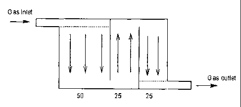
In the embodiment depicted in Figure 2, the baffle
plates 2 divide the stack of fuel cells 3 arbitrarily in
three sections of 50, 25 and 25 cells each. The supply of
gas is now first distributed between only 50 cells, rather
than 100, and consequently, the gas flow through each
individual cell in the first section is doubled. Similarly,
in section two and three, which only have 25 cells each, the
gas flow in the section is further doubled to 4
liters/minute. Thus a significant increase in gas flow
through individual cells is achieved. Furthermore, while the
gas is gradually depleted for the active component
(hydrogen) on its way through the stack, the fuel cell stack
design of the present invention ensures that the depletion
is compensated by a stepwise increase in the flow rate and
in the corresponding stoichiometric excess as expressed by
the A-value.
Another embodiment of the present invention is depicted
in Figure 3. Figure 3 shows a stack of 70 cells divided in
four sections having 30, 20, 12 and 8 single cells,
respectively.
For effective operation of a fuel cell stack, the rate
of the gas flow of the fuel gas is adjusted to correspond to
an overall stoichiometry of A = 1.2. That is, a 20%
stoichiometric excess of fuel gas is applied to the stack as
is commonly the case in a conventional stack design.
The exact amount of hydrogen needed in the fuel cell
stack to provide this stoichiometric excess can be
determined as follows:
CA 02594755 2007-07-12
WO 2006/077477 PCT/IB2006/000057
8
QH is defined as units of hydrogen which corresponds to
the exact stoichiometric amount of hydrogen needed for the
production of the required current in any single cell, i.e.
A = 1Ø For the desired excess value of A = 1 . 2 (Ae), the
following formula is used to calculate QH.
Ae * A * number of cells in stack = QH
Thus, for a stack of 70 cells wherein Ae is 1.2 and A is 1,
the units of hydrogen or QH are 84.
For a fuel cell stack designed in accordance with the
present invention, such as that exemplified in Figure 3,
wherein the first section of the stack contains 30 single
cells, each consuming one unit QH of hydrogen, after passage
of the fuel through first section, the number of hydrogen
units is reduced to 54 QH units. The effective anode
stoichiometry of the first section, Al is 84/30 or 2.8.
The effective stoichiometries of the following sections
of the fuel cell stack of the present invention designed in
accordance with the exemplary embodiment depicted in Figure
3 can be calculated in a similar manner. The resulting
calculated stoichiometries are summarized in Table 1.
TABLE 1:
it cells QH units QH units AX effective
used remaining
30 54 2.8
20 20 34 2.7
12 12 22 2.8
8 8 14 2.8
As shown in Table 1, dividing the fuel cell stack into
25 sections with baffle plates and directing the fuel gas
sequentially through the several sections, the nominal
stoichiometry is increased from A = 1.2, to an effective
CA 02594755 2007-07-12
WO 2006/077477 PCT/IB2006/000057
9
value of approximately 2.8 in each of the several sections
of the stack.
This increase in nominal stoichiometry of the fuel cell
stack design of the present invention was shown to provide
for a more effective fuel cell stack with reformer gases.
Figure 4 shows results from experiments measuring the
voltage as a function of A for a conventional fuel cell
stack containing 25 cells with a parallel connected gas
flow. The stack was constructed similarly to the stack
depicted in Figure 1. At values of A above 1.50 the cell
operated flawlessly, and there were no indications of
malfunction. However, while the operation continued
unaffected down to A approximately equal to 1.1 - 1.2 when
pure hydrogen was used as the fuel gas, the voltage
decreased dramatically below A = 1.50 when reformer gas was
used.
In contrast, with a fuel cell stack designed in
accordance with the present invention virtually no deviation
was observed when the stack was fed with reformer gas
containing nitrogen and only a small deviation was observed
when carbon dioxide was used, compared to using pure
hydrogen fuel gas (see Figure 5).
As will be understood by those skilled in the art upon
reading this disclosure, while the present invention has
been illustrated by the exemplary embodiments depicted in
Figure 2 and 3, it is foreseen that other designs based on
this method are possible.