Note : Les descriptions sont présentées dans la langue officielle dans laquelle elles ont été soumises.
CA 02602682 2007-09-27
WO 2006/104377 PCT/NL2005/050001
METHDD FM PRODtTCIbTG A PZOATING Bkoz
The invention relates to a method for producing a floating
base, which base is made up of a number of coupled-together
base elements. The base according to the invention, which
floats on water, is in particular suitable for placing at
least a building, such as a house, a row of houses or an
office building, and/or any other structure, such as an
airfield or a soccer field, a restaurant, a hotel, a church, a
garden or a park thereon.
It is noted that the demand for floating building lots for use
as the base structure in particular for buildings, squares,
roads and green areas is increasing worldwide. In particular
the demand for building space in the vicinity of towns and
cities and the like is increasing. Essential is that floating
building lots are stable and consequently do not exhibit any
unacceptable swell-induced rolling motion.
Such a method is known from US patent No. 5,044,296 (Finn).
The known method employs coupled-together floating modules, in
particular for assembling a dock. Said floating modules are
each built up of block of a foam material ("Styrofoamn), on
which a protective coating has been sprayed so as to prevent
water penetrating the foam material. Each floating module is
furthermore provided at the upper side thereof with a cover
layer consisting of glass fibre-reinforced concrete. Rods
projecting from the blocks function to connect adjacent
modules.
One drawback of the method disclosed in the aforesaid US
patent publication is the fact that the floating modules are
CA 02602682 2007-09-27
WO 2006/104377 PCT/NL2005/050001
2
constructed in a laborious and complex process, whilst the
materials that are used are not always readily available at
any place on earth. Because of this, the aforesaid method
according to the prior art has a limited applicability.
The object of the invention is to overcome the drawbacks of
the prior art and in particular to propose an inexpensive and
simple method for producing a stable base that floats on
water, wherein the base is assembled from a number of coupled-
together, simple base elements in a flexible manner.
in order to accomplish that objective, a method of the kind
referred to in the introduction is characterized in that
floating elements and rigid elements are supplied first, after
which a number of floating elements and a number of rigid
elements are joined together, wherein each base element is
assembled from floating elements and rigid elements that have
been joined'together in this manner, after which a number of
base elements thus formed are coupled together so as to form
the floating base. The essence of the invention is that it
departs from base elements which (i) are made up of units that
can be produced at low cost anywhere in the world and which
are easy to transport and to combine, and which (ii), in
coupled-together condition, form a stable, floating base. The
base elements can be flexibly coupled together in such a
manner that the floating base can have any shape and
dimensions that may be desired.
Accordingly, the present invention makes use of preformed
floating and rigid elements, both types.of elements preferably
being provided with a quality mark. In this way it can be
ensured in advance that the calculated minimum rigidity of the
floating base equals the rigidity of the floating base as
implemented in practice. For each construction project the
CA 02602682 2007-09-27
WO 2006/104377 PCT/NL2005/050001
3
required number of floating and rigid elements and the
required dimensions of said floating and rigid elements are
determined in advance. No concrete is locally poured to form
the base elements. The fact is that.in those cases in which
concrete is poured no clarity can be obtained in advance as to
the realised rigidity of the installed floating base.
Furthermore, pouring concrete has this drawback that concrete
may be wasted, with all the consequent ecological damage,
whilst in addition construction depends on all kinds of
meteorological conditions in that case.
In one preferred embodiment of a method according to the
invention, the floating elements and the rigid elements are
joined together on land. In another preferred variant, the
floating elements and the rigid elements are joined together
on a vessel that floats. on the water, such as a work boat or a
pontoon. More in particular, a flat bed is first formed on
land or on the vessel, after which the floating elements and
the rigid elements are joined together on said bed. Said bed,
which functions as a supporting surface, is prepared on the
land or on the vessel in advance, therefore. A poured concrete
floor is very suitable for use as a flat bed. In a first
preferred embodiment, the invention therefore proceeds from
the idea that the joining together of the floating elements
and the rigid elements, i.e. the assembling of the floating
base elements ("modules") therefrom, takes place on land, thus
avoiding the laborious, time-consuming and dangerous work on
the water during that stage. In another, second preferred
embodiment the joining together of the floating elements and
the rigid elements takes place on the vessel, that is floating
on the water, such as the aforesaid work boat or pontoon.
In another preferred embodiment of a method according to the
invention, the floating elements and the rigid elements are
CA 02602682 2007-09-27
WO 2006/104377 PCT/NL2005/050001
4
joined together under a bias. As a result of said biasl a
friction surface is formed between the floating elements on
the one hand and the rigid elements on the other hand. This
achieves that the base elements thus assembled remain rigid up
to a predetermined, safe load (i.e. bias) and consequently can
be transported into the water without any problems. The
floating base made up of base elements thus has a guaranteed
minimum rigidity so that it can at all times function as an
insubmersible base structure, in particular for a building to
be placed thereon.
In another preferred embodiment of a method according to the
invention, a rod is first passed through the floating elements
and the rigid elements, after which the bias is applied by
tightening nuts on the rod. In another preferred embodiment, a
strap is first arranged round the floating elements and the
rigid elements, after which the bias is applied by tightening='
the strap or pre-tensioning it by means of a"screw clamp
method".
In another preferred embodiment of a method according to the
invention, the base elements assembled from the joined-
together floating elements and rigid elements are placed in
the water from the land or from a vessel that floats on the
water. The base elements are in particular hoisted into the
water from the land or from the vessel, for example by means
of a crane. According to another possibility, the base
elements slide into the water from the vessel. This preferred
embodiment comprises an initial phase, therefore, in which the
floating elements and the rigid elements are combined to form
the base elements (preferably under a bias, i.e. through
friction between the floating elements and the rigid elements)
on land or on the vessel, and an end phase, in which the
floating base is/has been made up of the coupled-together base
CA 02602682 2007-09-27
WO 2006/104377 PCT/NL2005/050001
elements on the water. Preferably, fixation means are provided
on the floating base after the assembly thereof to prevent the
floating elements from becoming detached from one base element
or from several base elements in case the aforesaid bias
5 should decrease after some time. It is noted that such
fixation means can be provided on individual base elements or
on a number of base elements lying adjacently to each other.
Such a fixation means is in particular a rigid upper plate,
such as a poured concrete floor or a constructed wooden,
plastic or metal floor.
In another preferred embodiment of a method according to the
invention, the floating elements are block-shaped. More in
particular, the floating elements are made of expanded
polystyrene (hereinafter abbreviated "EPS"}, also referred to
as-"styroporp in practice.
In another preferred embodiment of a method according to the
invention, the rigid elements are plate-shaped. The rigid
elements are preferably made of concrete. In another preferred
embodiment, the rigid elements are made of laminated wood,
steel, aluminium or plastic.
In another preferred embodiment of a method according to the
2S invention, base elements positioned adjacently to each other
are coupled-together on the water by inserting outwardly
extending projections of rigid elements of one base element
into corresponding slots in rigid elements of the other,
adjacent base element: This wi1l be explained in more detail
yet in the description of the figures.
In another preferred embodiment of a method according to the
invention, fixation means are provided on the coupled-together
base elements on the water so as to fix the floating elements
CA 02602682 2007-09-27
WO 2006/104377 PCT/NL2005/050001
6
in position with respect to the rigid elements. As already
noted above, the fixation means are preferably embodied as a
rigid upper plate, such as a concrete floor.
The invention also relates to a floating base made up of a
number of coupled-together base elements, characterized in
that each base element has been assembled from a number of
floating elements and rigid elements that have been joined
together under a bias (and friction).
The invention will now be explained in more detail with
reference to figures illustrated in a drawing, in which Figs.
1-16 show successive steps of a preferred embodiment of a
method for producing a floating base according to the
invention.
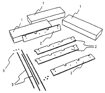
Fig. 1 shows elements that form components of each base
element, viz. floating elements in the form of EPS blocks 1,
rigid elements formed by concrete plates or slabs 2, as well
as rods and nuts, jointly indicated at 3. These components are
readily available and easy to transport, for example by means
of a truck.
Fig. 2 shows a first step of the production of the floating
base, viz. the forming of a flat bed or supporting surface 4
on land. This can be done by pouring aÃlat concrete floor on
the ground or laying a flat floor of wood or plastic on the
ground. Possibly, a flat floor consisting of rubble or sand is
laid on the ground. The flat bed 4 functions to prevent
excessive variations in height between the EPS blocks 1 and
the concrete plates or slabs 2 when said elements are being
joined together to form base elements for the floating base.
CA 02602682 2007-09-27
WO 2006/104377 PCT/NL2005/050001
7
In the second and third step (Figs. 2 and 3) the concrete
plates 2 (slabs) are placed on the flat bed 4 with their
narrow longitudinal sides, leaving open a space 5 between the
respective plates (Fig. 2). Then an EPS block 1 is placed in
each space 5 (Fig. 3). Concrete plates (slabs) 2 and EPS
bl.ocks 1 are arranged in alternating relationship (seen in
horizontal direction), therefore. In principle it would also
be possible to stack the concrete plates 2(slabs) and the EPS
blocks 1 in vertical direction.
Figs. 4, 5, 6 and 7 show a fourth step, in which the concrete
plates 2 and the EPS blocks I of Figs. 3 are joined together
under a bias. To that end a bar or rod 6, e.g. of stainless
steel, is inserted into pre-drilled holes (not shown) in the
concrete plates (slabs) 2 and the EPS blocks 1, after which
nuts 7 present on either side of the whole are tightened to at
least the calculated bias, thus providing the required
friction tension on the contact surfaces of the rigid elements
and the floating elements. Thus a biased base element 8 is
obtained (Fig. 7). The bias, i.e. the friction between the
concrete plates 2 (slabs) in a base element 8 on the one hand
and the EPS blocks 1 in a base element 8 on the other hand
provides (i) the required rigidity of the base element 8, as a
result of which the base element can be transported (for
example hoisted or slipped) into the water as an independent
"module" and (ii) the rigidity required for provisionally
keeping the=base elements 8 together on the water. After a
concrete floor 17 has been poured on individual base elements
8 or on several base elements together, the aforesaid bias
(i.e. friction between the elements 1, 2 in the base elements
8 ("modules")) is no longer required. The fact is that the
concrete floor 17 provides the necessary rigidity in that
case. In the unlikely event that the aforesaid bias should be
lost entirely or partially after some t3.me, the concrete floor
CA 02602682 2007-09-27
WO 2006/104377 PCT/NL2005/050001
8
17 will prevent the EPS blocks 1 from becoming detached from
one base elment or several base elements. The concrete floor
17 will function as a fixation elment in that case to hold
the EPS blocks 1 in place.
Figs. 8 and 9 show in a fifth step the manner in which a base
element 8 that has been built up on land is hoisted onto or
into the water from the land by means of a crane.
Figs. 10-16 show next steps, in which the floating base is
assembled by coupling or linking together base elements 8
positioned adjacently to each other, as shown in Figs. 8 and
9. The base elements 8 are preferably laid alternately in
longitudinal direction and in transverse direction (Figs. 10
1S and 11) on the water. The coupling together of adjacent base
elements 8 takes place by inserting projections 11 on the
concrete plates 2 of one base element 8 into slots 12 in the
concrete plates 2 of the other base elment 8, and
subsequently inserting locking pins 13 vertically into the
projections 11 (Figs. 10, 11 and 12). Fig. 13 shows the
installation of pipes 14 (e.g. water pipes, electric lines,
sewage pipes) in the coupled-together base elements 8, which
pipes 14 are installed in channels 15 milled in situ in the
concrete plates 2 and the EPS blocks 1 of the base e7.ements 8.
Possibly, pre-formed channels 15 or holes are formed. Finally,
a fabric 16 is laid on top of the floating base, after which
the concrete floor 17 is poured (Figs. 14 and 15). Before the
concrete is poured, a formwork 18 is placed all around the
base. The floating base (indicated at 19 in Fig. 16) is now
ready to function as a floating base structure for all kinds
of functional structures, such as one or more buildings, green
areas, infrastructure (roads, railway lines and the like),
airfields, sports fields, etc. The floating base 19 is a very
CA 02602682 2007-09-27
WO 2006/104377 PCT/NL2005/050001
9
stable in the sense that it will exhibit hardly any swell-
induced rolling motion, if at all.
It is noted that the invention is not limited to the
illustrated embodiment, but that it also extends to other
preferred variants that fall within the scope of the appended
claims. Thus it will be apparent to those skilled in the art
that the blocks 1 and the plates 2 may have any desired shape
and dimension and need not necessarily be made of EPS and
concrete, respectively, with this understanding that a
floating material and a rigid material, respectively, must be
used. In this context the term floating material is understood
to be a material having a specific weight less than or equal
to 1 g/cm3. Furthermore it will be apparent to those skilled
in the art that the blocks 1 and the plates 2 need not
necessarily be positioned on the water in the illustrated
configuration, but that any,desired pattern is possible.
Finally it will be appar'ent to those skilled in the art that
instead of the concrete floor 17 any fixation means may be
used for holding the floating elements in place when the bias
is at least partially lost, for example a rigid upper plate
made of wood, a metal or a plastic.