Sélection de la langue

Search

Sommaire du brevet 2604931 

Énoncé de désistement de responsabilité concernant l'information provenant de tiers

Une partie des informations de ce site Web a été fournie par des sources externes. Le gouvernement du Canada n'assume aucune responsabilité concernant la précision, l'actualité ou la fiabilité des informations fournies par les sources externes. Les utilisateurs qui désirent employer cette information devraient consulter directement la source des informations. Le contenu fourni par les sources externes n'est pas assujetti aux exigences sur les langues officielles, la protection des renseignements personnels et l'accessibilité.

Disponibilité de l'Abrégé et des Revendications

L'apparition de différences dans le texte et l'image des Revendications et de l'Abrégé dépend du moment auquel le document est publié. Les textes des Revendications et de l'Abrégé sont affichés :

  • lorsque la demande peut être examinée par le public;
  • lorsque le brevet est émis (délivrance).
(12) Brevet: (11) CA 2604931
(54) Titre français: DISPOSITIF D'ECARTEMENT DE CABLES DESTINE A DES TREILLIS DE CABLES
(54) Titre anglais: SPREADING DEVICE FOR ROPE NETWORKS
Statut: Octroyé
Données bibliographiques
(51) Classification internationale des brevets (CIB):
  • A63B 9/00 (2006.01)
(72) Inventeurs :
  • KOEHLER, KARL-HEINZ (Allemagne)
(73) Titulaires :
  • BERLINER SEILFABRIK GMBH & CO. (Allemagne)
(71) Demandeurs :
  • BERLINER SEILFABRIK GMBH & CO. (Allemagne)
(74) Agent: DEETH WILLIAMS WALL LLP
(74) Co-agent:
(45) Délivré: 2013-10-01
(86) Date de dépôt PCT: 2006-04-13
(87) Mise à la disponibilité du public: 2006-10-19
Requête d'examen: 2011-02-24
Licence disponible: S.O.
(25) Langue des documents déposés: Anglais

Traité de coopération en matière de brevets (PCT): Oui
(86) Numéro de la demande PCT: PCT/EP2006/003785
(87) Numéro de publication internationale PCT: WO2006/108716
(85) Entrée nationale: 2007-10-12

(30) Données de priorité de la demande:
Numéro de la demande Pays / territoire Date
20 2005 006 174.3 Allemagne 2005-04-13
10 2005 017 774.3 Allemagne 2005-04-13
10 2005 026 412.3 Allemagne 2005-06-03
20 2005 009 003.4 Allemagne 2005-06-03
20 2006 004 853.7 Allemagne 2006-03-22

Abrégés

Abrégé français

L'invention concerne un dispositif d'écartement de câbles destiné à des treillis de câbles présentant des câbles de haubanage se rejoignant sur le point supérieur d'un mât support. L'invention vise à combler le manque de volume de jeu et à permettre de varier la tension des câbles de haubanage. A cet effet, on fait intervenir un dispositif d'écartement caractérisé en ce qu'un écartement de câbles est prévu entre un câble de haubanage et un mât support. L'écartement de câbles dévie le câble de haubanage de manière à obtenir un plus grand volume pouvant servir à des activités de grimpe et de jeu, entre les câbles de haubanage et le mât support central. L'écartement de câbles permet de varier le degré de l'écartement et la tension des câbles de haubanage.


Abrégé anglais


The invention relates to a rope spreading device for rope networks
with tensioning ropes that converge at a top point of a support mast at
an acute angle. It is an object of the invention to overcome the lack of
play space, while making it also possible to vary the tension of the
tensioning ropes. Accordingly, a rope spreading device is provided for
rope networks with tensioning ropes that converge at a top point of a
support mast at an acute angle, wherein the device is characterized in
that at least one rope spreader is arranged between a tensioning rope
and a support mast. The rope spreader changes the path of the
tensioning rope so that a greater usable volume is created between
the tensioning ropes and the central support mast, which can be used
for climbing and play. Advantageously, the rope spreader may be used
to vary the degree of spreading and the tension of the tensioning
ropes.

Revendications

Note : Les revendications sont présentées dans la langue officielle dans laquelle elles ont été soumises.


Claims
1. A three-dimensional network of rope netting, wherein the network of
rope netting comprises:
tensioning ropes that extend on the outside of the network and
converge at a top point of a support mast at an acute angle relative to the
support mast, wherein the support mast is arranged within the network; and
at least one rope spreader arranged between at least one tensioning
rope of the network of rope netting and the support mast,
wherein the at least one rope spreader has a spreader rod attached to
the support mast and affixed on the at least one tensioning rope, and
further wherein the spreader rod is moveably attached to a rope
attachment on the side of the at least one tensioning rope and is attached
on the side of the support mast for articulation about a pivot point of a
spreader rod attachment disposed on the support mast.
2. The network according to claim 1, wherein the spreader rod is
configured to be lengthened and shortened in an axial direction of the
spreader rod.
3. The network according to claim 1, wherein the rope attachment
comprises:
an upper element;

9

a lower element; and
a bolt,
wherein the at least one tensioning rope is secured between the upper
element and the lower element with the bolt.


Description

Note : Les descriptions sont présentées dans la langue officielle dans laquelle elles ont été soumises.


CA 02604931 2007-10-12

SPREADING DEVICE FOR ROPE NETWORKS

The invention relates to a rope spreading device for rope networks
with tensioning ropes that converge at a top point of a support mast at
an acute angle.

Two-dimensional and three-dimensional networks of rope netting in
combination with variable scaffolding systems have been successfully
employed in the design of playgrounds. These networks are suitable
for implementing different play worlds with three-dimensional
structures that encourage children to exercise. The networks
composed of different ropes are tensioned inside a predefined
scaffolding system, wherein the scaffolding attains significant flexibility
when the individual scaffold rods are connected by spherical hollow
bodies, allowing the creation of many interesting geometrically shapes.
The rope networks are attached and tensioned inside the scaffolds with
the help of mounts disposed on or in the hollow spherical bodies and
on the scaffolding rods.

Particular designs of three-dimensional network structures can be
attained by arranging the ropes extending from the support masts in a
three-dimensional pattern and then tensioning the ropes. The

1


CA 02604931 2007-10-12

tensioning ropes, which for geometric reasons converge at a top point
of a support mast at an acute angle, are typically tensioned with
turnbuckles arranged close to the ground at the foundation. In
conventionally tensioned playground networks, the actual play volume

in the upper region of the support mast becomes increasingly smaller
at the top point where the tensioning ropes converge at an acute
angle. The disadvantage of a smaller play volume, in particular in the
upper and center region of a support mast, becomes particularly
apparent with playground networks having a central mast located in
the center.

It is an object of the invention to eliminate these disadvantages,
namely the lack of play space, while making it also possible to vary the
tension of the tensioning ropes.

The object is attained by the features of claim 1. Accordingly, a rope
spreading device is provided for rope networks with tensioning ropes
that converge at a top point of a support mast at an acute angle,

wherein the device is characterized in that at least one rope spreader
is arranged between a tensioning rope and a support mast. The rope
spreader changes the path of the tensioning rope so that a greater
usable volume is created between the tensioning ropes and the central

2


CA 02604931 2007-10-12

support mast, which can be used for climbing and play.
Advantageously, the degree of spreading and the tension of the
tensioning ropes can be varied using the rope spreader.
Advantageous embodiments of the invention are recited in the
dependent claims.

In an advantageous embodiment of the invention, the rope spreader
includes a spreader rod attached to the support mast and to the
tensioning rope. The spreader rod is clamped therebetween so as to
push the tensioning rope away from the support mast, as compared
with the original path of the rope, thereby increasing the play volume.
As a result, the spreader rods advantageously combine, both visually
and functionally, with the rope network and can be used as part of the
climbing scaffold.

In another embodiment of the invention, the spreader rod is movably
attached to a rope attachment on the side of the tensioning rope and
is pivotally supported on the side of the support mast for articulation
about a pivot point of a spreader rod attachment disposed on the
support mast. The direction of the path of the tensioning ropes can


CA 02604931 2007-10-12

hereby advantageously be changed by changing the angle between the
support mast and the spreader rod.

According to another advantageous embodiment of the invention, the
spreader rod attachment is movably secured on the support mast.
Because the spreader rod attachment is movable on the support mast
in the axial direction, the tensioning ropes can be spread at different
positions on the support mast.

According to yet another advantageous embodiment, the spreader rod
can be lengthened and shortened in the axial direction. The tension of
the tensioning ropes can then be adjusted by changing the length of
the spreader rod between the support mast and the tensioning rope,
and/or the play volume can be changed by changing the degree of
spreading.

The invention will now be described in more detail with reference to an
exemplary embodiment and a drawing.

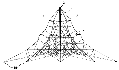
FIG. 1 shows a three-dimensional network with a support mast and
a spreader device disposed in the upper region of the support
mast,


CA 02604931 2007-10-12

FIG. 2 shows a three-dimensional network with a support mast and
rope spreader devices arranged in the upper and the center
region of the support mast,

FIG. 3 shows a detailed diagram of the rope spreader device,

FIG. 4 shows a detailed diagram of the attachment of the spreader
rod to the rope, and

FIG. 5 shows a cross-sectional view of the rope attachment.

FIG. 1 shows a three-dimensional network, wherein one support mast
1 is implemented as a center mast. Tensioning ropes 2 converge at a
top point 3 of the support mast 1 and are securely anchored on the
ground by turnbuckles 15. Several rope spreaders 4 are arranged in
the upper region of the support mast 1, wherein each tensioning rope
2 has a dedicated rope spreader 4. The tensioning ropes 2, which
initially converge at an acute angle, are pushed outward in the
spreading region, thereby advantageously producing a larger play
volume. Playing children enjoy greater freedom to move in the rope
network structures disposed between the tensioning ropes 2.


CA 02604931 2007-10-12

FIG. 2 shows another three-dimensional network of rope netting with a
support mast 1 which is also implemented as a center mast. The
tensioning ropes 2 on the outside are retained at the top point 3 of the
support mast 1 and on the bottom turnbuckles 15 located close to the
ground. Additional rope spreaders 4 commensurate with the number
of tensioning ropes 2 are arranged in the center region of the support
mast 1, thereby further increasing the play volume. The rope
spreaders 4 are designed so as to visually combine in with the existing
three-dimensional rope network structures.

FIG. 3 shows an exemplary embodiment of a rope spreader 4. The
rope spreader 4 has a spreader rod 5 which is movably attached to a
rope attachment 6 on the side of the tensioning rope and is pivotally
attached on the side of the support mast for articulation about a pivot
point 10 of a spreader sleeve 9. Pivot points 10 are attached to the
tensioning sleeve 9, enabling articulation of the spreader rod 5. The
spreader rod 5 can be axially lengthened or shortened with a rod
extension 8, so that the degree of spreading and the tension of
tensioning rope 2 can also be adjusted. For example, the rod
extension 8 may be a threaded rod which can be screwed in and
unscrewed from the spreader rod 5.

0


CA 02604931 2007-10-12

FIG. 4 shows an exemplary embodiment of the rope attachment 6 on
the spreader rod 5, employing two tensioning ropes 2.

FIG. 5 shows schematically the rope attachment 6 in cross-section.
The two parallel tensioning ropes 2 are securely screwed together in
the spreader rod 5 between an upper element 12 and a lower element
13 with a threaded bolt 14. The attachment point of the spreader rod
on the tensioning ropes 2 can be moved by reducing the pressing
force between the upper element 12 and the lower element 13.

7


CA 02604931 2007-10-12
List of reference symbols

1 Support mast

2 Tensioning rope
3 Top point

4 Rope spreader
Spreader rod

6 Rope attachment
7 Mast attachment
8 Rod extension

9 Tensioning sleeve
Pivot point

11 Spreader rod attachment
12 Upper element

13 Lower element
14 Threaded bolt

Bottom rope tensioner

S

Dessin représentatif
Une figure unique qui représente un dessin illustrant l'invention.
États administratifs

Pour une meilleure compréhension de l'état de la demande ou brevet qui figure sur cette page, la rubrique Mise en garde , et les descriptions de Brevet , États administratifs , Taxes périodiques et Historique des paiements devraient être consultées.

États administratifs

Titre Date
Date de délivrance prévu 2013-10-01
(86) Date de dépôt PCT 2006-04-13
(87) Date de publication PCT 2006-10-19
(85) Entrée nationale 2007-10-12
Requête d'examen 2011-02-24
(45) Délivré 2013-10-01

Historique d'abandonnement

Il n'y a pas d'historique d'abandonnement

Taxes périodiques

Dernier paiement au montant de 473,65 $ a été reçu le 2023-03-31


 Montants des taxes pour le maintien en état à venir

Description Date Montant
Prochain paiement si taxe applicable aux petites entités 2024-04-15 253,00 $
Prochain paiement si taxe générale 2024-04-15 624,00 $

Avis : Si le paiement en totalité n'a pas été reçu au plus tard à la date indiquée, une taxe supplémentaire peut être imposée, soit une des taxes suivantes :

  • taxe de rétablissement ;
  • taxe pour paiement en souffrance ; ou
  • taxe additionnelle pour le renversement d'une péremption réputée.

Les taxes sur les brevets sont ajustées au 1er janvier de chaque année. Les montants ci-dessus sont les montants actuels s'ils sont reçus au plus tard le 31 décembre de l'année en cours.
Veuillez vous référer à la page web des taxes sur les brevets de l'OPIC pour voir tous les montants actuels des taxes.

Historique des paiements

Type de taxes Anniversaire Échéance Montant payé Date payée
Le dépôt d'une demande de brevet 400,00 $ 2007-10-12
Taxe de maintien en état - Demande - nouvelle loi 2 2008-04-14 100,00 $ 2008-03-07
Taxe de maintien en état - Demande - nouvelle loi 3 2009-04-14 100,00 $ 2009-04-06
Taxe de maintien en état - Demande - nouvelle loi 4 2010-04-13 100,00 $ 2010-03-30
Requête d'examen 800,00 $ 2011-02-24
Taxe de maintien en état - Demande - nouvelle loi 5 2011-04-13 200,00 $ 2011-03-31
Taxe de maintien en état - Demande - nouvelle loi 6 2012-04-13 200,00 $ 2012-03-27
Taxe de maintien en état - Demande - nouvelle loi 7 2013-04-15 200,00 $ 2013-04-03
Taxe finale 300,00 $ 2013-07-17
Taxe de maintien en état - brevet - nouvelle loi 8 2014-04-14 200,00 $ 2014-04-02
Taxe de maintien en état - brevet - nouvelle loi 9 2015-04-13 200,00 $ 2015-03-31
Taxe de maintien en état - brevet - nouvelle loi 10 2016-04-13 250,00 $ 2016-03-30
Taxe de maintien en état - brevet - nouvelle loi 11 2017-04-13 250,00 $ 2017-03-30
Taxe de maintien en état - brevet - nouvelle loi 12 2018-04-13 250,00 $ 2018-04-03
Taxe de maintien en état - brevet - nouvelle loi 13 2019-04-15 250,00 $ 2019-04-03
Taxe de maintien en état - brevet - nouvelle loi 14 2020-04-14 250,00 $ 2020-03-31
Taxe de maintien en état - brevet - nouvelle loi 15 2021-04-13 459,00 $ 2021-03-29
Taxe de maintien en état - brevet - nouvelle loi 16 2022-04-13 458,08 $ 2022-04-06
Taxe de maintien en état - brevet - nouvelle loi 17 2023-04-13 473,65 $ 2023-03-31
Titulaires au dossier

Les titulaires actuels et antérieures au dossier sont affichés en ordre alphabétique.

Titulaires actuels au dossier
BERLINER SEILFABRIK GMBH & CO.
Titulaires antérieures au dossier
KOEHLER, KARL-HEINZ
Les propriétaires antérieurs qui ne figurent pas dans la liste des « Propriétaires au dossier » apparaîtront dans d'autres documents au dossier.
Documents

Pour visionner les fichiers sélectionnés, entrer le code reCAPTCHA :


Pour visualiser une image, cliquer sur un lien dans la colonne description du document. Pour télécharger l'image (les images), cliquer l'une ou plusieurs cases à cocher dans la première colonne et ensuite cliquer sur le bouton "Télécharger sélection en format PDF (archive Zip)" ou le bouton "Télécharger sélection (en un fichier PDF fusionné)".

Liste des documents de brevet publiés et non publiés sur la BDBC .

Si vous avez des difficultés à accéder au contenu, veuillez communiquer avec le Centre de services à la clientèle au 1-866-997-1936, ou envoyer un courriel au Centre de service à la clientèle de l'OPIC.


Description du
Document 
Date
(yyyy-mm-dd) 
Nombre de pages   Taille de l'image (Ko) 
Revendications 2007-10-12 2 38
Abrégé 2007-10-12 1 23
Dessins 2007-10-12 5 112
Description 2007-10-12 8 198
Dessins représentatifs 2008-01-10 1 18
Page couverture 2008-01-11 1 53
Revendications 2012-10-31 2 34
Abrégé 2013-02-20 1 23
Page couverture 2013-09-05 1 56
Taxes 2011-03-31 1 38
Correspondance 2008-01-23 1 31
PCT 2007-10-12 4 170
Cession 2007-10-12 3 95
Correspondance 2008-01-09 1 24
Taxes 2008-03-07 1 34
Taxes 2009-04-06 1 41
Taxes 2010-03-30 1 38
Poursuite-Amendment 2011-02-24 1 40
Taxes 2012-03-27 1 38
Poursuite-Amendment 2012-05-16 3 100
Poursuite-Amendment 2012-10-31 7 204
Taxes 2013-04-03 1 40
Correspondance 2013-07-17 1 42