Sélection de la langue

Search

Sommaire du brevet 2608038 

Énoncé de désistement de responsabilité concernant l'information provenant de tiers

Une partie des informations de ce site Web a été fournie par des sources externes. Le gouvernement du Canada n'assume aucune responsabilité concernant la précision, l'actualité ou la fiabilité des informations fournies par les sources externes. Les utilisateurs qui désirent employer cette information devraient consulter directement la source des informations. Le contenu fourni par les sources externes n'est pas assujetti aux exigences sur les langues officielles, la protection des renseignements personnels et l'accessibilité.

Disponibilité de l'Abrégé et des Revendications

L'apparition de différences dans le texte et l'image des Revendications et de l'Abrégé dépend du moment auquel le document est publié. Les textes des Revendications et de l'Abrégé sont affichés :

  • lorsque la demande peut être examinée par le public;
  • lorsque le brevet est émis (délivrance).
(12) Brevet: (11) CA 2608038
(54) Titre français: ENSEMBLE GENERATEUR DE CHALEUR A TUBE RADIANT
(54) Titre anglais: RADIANT TUBE HEATER ASSEMBLY
Statut: Octroyé
Données bibliographiques
(51) Classification internationale des brevets (CIB):
  • F23C 3/00 (2006.01)
  • F23D 14/22 (2006.01)
(72) Inventeurs :
  • VANCAK, JOHN (Canada)
(73) Titulaires :
  • VANCAK, JOHN (Canada)
(71) Demandeurs :
  • VANCAK, JOHN (Canada)
(74) Agent: CASSAN MACLEAN IP AGENCY INC.
(74) Co-agent:
(45) Délivré: 2014-05-13
(22) Date de dépôt: 2007-10-17
(41) Mise à la disponibilité du public: 2008-05-17
Requête d'examen: 2012-10-03
Licence disponible: S.O.
(25) Langue des documents déposés: Anglais

Traité de coopération en matière de brevets (PCT): Non

(30) Données de priorité de la demande:
Numéro de la demande Pays / territoire Date
11/600,888 Etats-Unis d'Amérique 2006-11-17

Abrégés

Abrégé français

Un appareil de chauffage à tube radiant comprend un logement et un tube de brûleur qui se prolonge vers l'extérieur de celui-ci pour transporter les produits de combustion hors du logement. Quand il faut moins de chaleur, à moins de réduire l'air de la soufflante, il y a trop d'air pour une combustion complète du combustible et l'excédent d'air se mélange avec les gaz de combustion, causant un refroidissement dans le tube du brûleur. Ce problème est résolu en fournissant un tube à flamme courte dans l'entrée du tube du brûleur pour recevoir la flamme. Le flot d'air excédentaire autour du tube de la flamme est chauffé. Ainsi, il est nécessaire de réduire seulement l'approvisionnement en combustible vers le brûleur.


Abrégé anglais

A radiant tube heater includes a housing and a burner tube extending outwardly therefrom for carrying products of combustion from the housing. When less heat is required, unless air from the blower is reduced, there is too much air for complete combustion of the fuel and excess air mixes with combustion gases causing cooling in the burner tube. This problem is solved by providing a short flame tube in the inlet end of the burner tube for receiving the flame. Excess air flow around the flame tube is heated. Thus, it is necessary to reduce only the supply of fuel to the burner.

Revendications

Note : Les revendications sont présentées dans la langue officielle dans laquelle elles ont été soumises.


CLAIMS:

1. A radiant tube heater comprising a housing; an opening in one end of
said
housing; a burner tube extending outwardly from said housing around said
opening; a
burner in said housing spaced apart from said opening; a gas inlet extending
into said
housing and connected to said burner for introducing fuel into said burner; a
blower in
said housing for introducing combustion air into the housing for mixing with
the fuel and
for blowing a flame and the products of combustion out of the housing into
said burner
tube; and a flame tube in said burner tube for receiving the flame, the flame
tube
extending a short distance from the opening into the burner tube, whereby air
required
for efficient combustion of the gases passes between the burner and the
opening to
create the flame, which is blown through the opening and then through the
flame tube,
and excess air exiting the housing through the opening passes between the
burner tube
and the flame tube for heating by the flame tube.
2. The radiant tube heater of claim 1, wherein said flame tube is attached
to one
side of the burner tube.
3. The radiant tube heater of claim 2, wherein said flame tube extends
along the
bottom of the burner tube.
4. The radiant tube heater of claim 1, wherein said flame tube is centered
in said
burner tube, whereby excess air passes completely around the flame tube,
5. The radiant tube heater of claim 4 including a plurality of rods
extending radially
between said burner tube and said flame tube for centering and supporting the
flame
tube in the burner tube.

Description

Note : Les descriptions sont présentées dans la langue officielle dans laquelle elles ont été soumises.


CA 02608038 2007-10-17

RADIANT TUBE HEATER ASSEMBLY
BACKGROUND OF THE INVENTION
FIELD OF THE INVENTION

This invention relates to a radiant tube heater assembly.

The conventional radiant tube heater includes a housing containing a burner,
a burner tube extending out of the housing and a reflector connected to the
housing
and partially surrounding the burner tube. Gas is introduced into the burner
for
mixing with air from a blower attached to or mounted in the housing. The gas
flows
into the housing via an inlet line equipped with a valve. It is necessary to
control the

flow of gas and air in order to ensure complete combustion of the gas.
Otherwise,
excess air, i.e. air not required for complete combustion of the fuel enters
the burner
tube with the flame from the burner and cools the combustion gases immediately
downstream of the burner. Thus, when the supply of fuel to the burner is
reduced, it
is also necessary to decrease the blower fan speed so that less air is fed
into the

housing.

GENERAL DESCRIPTION OF THE INVENTION

The object of the present invention is to provide a radiant tube heater
assembly, which does not require a reduction in air flow when the heat is
turned
down, i.e. when the flow of gas into the burner is reduced by partly closing
the valve

in the gas inlet line or by the reduction of fuel pressure in the gas valve
and/or gas
regulator assembly.

In general terms, the above defined object is achieved by adding a short
flame tube in the inlet end of the burner tube so that air not required for
complete
combustion of the gas flows over the flame tube. During passage over the flame

1


CA 02608038 2007-10-17

tube, the air is heated and then mixes with the combustion gases downstream of
the
flame tube. Consequently, the combustion gases are not cooled or are cooled
less
than in existing burner tubes without a flame tube.

More specifically, the invention relates to a radiant tube heater comprising a
housing; an outlet in one end of said housing; a burner tube extending
outwardly
from said housing around said opening; a burner in said housing; a gas inlet
extending into said housing and connected to said burner for introducing fuel
into
said burner; a blower in said housing for introducing combustion air into the
housing
for mixing with the fuel and for blowing a flame and the products of
combustion into

said burner tube; and a flame tube in said burner tube for receiving the
flame,
whereby air required for efficient combustion of the gas passes through the
flame
tube, and excess air exiting the housing passes between the burner tube and
the
flame tube for heating by the flame tube.

BRIEF DESCRIPTION OF THE DRAWINGS

Figure 1 is an isometric view of one end of a radiant tube heater assembly;
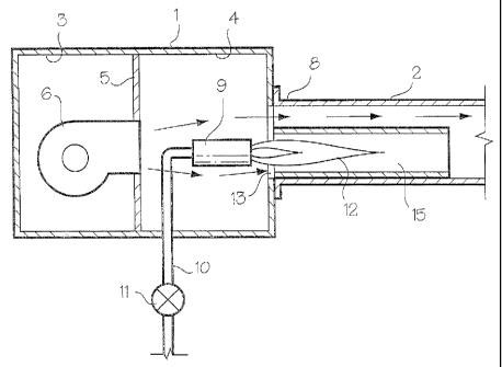
Figure 2 is a schematic longitudinal sectional view of the end of the heater
assembly of Fig. 1 and a flame tube in accordance with the present invention;

Figure 3 is a schematic longitudinal sectional view of one end of a heater
assembly containing a flame tube in accordance with a second embodiment of the
present invention;

Figure 4 is a schematic longitudinal sectional view of one end of a heater
assembly containing a flame tube in accordance with a third embodiment of the
invention; and

Figure 5 is an isometric view of the flame tube of Fig. 3.
2


CA 02608038 2007-10-17

DESCRIPTION OF THE PREFERRED EMBODIMENT

Referring to Figs. 1 and 2, a radiant tube heater assembly includes a housing
1 with a burner tube 2 extending outwardly therefrom. A reflector (not shown)
is
usually provided around the top and sides of the burner tube 2. The interior
of the

housing 1 is divided into a pair of chambers 3 and 4 by a partition 5. The
chamber 3
contains a blower 6 for introducing combustion air into the chamber 4 and the
inlet
end 8 of the burner tube 2. Gas is fed into a burner 9 in the chamber 4 via an
inlet
line 10 containing a valve 11.

In the conventional radiant heater, air from the blower 6 mixes with fuel

entering the burner 9 via the tube 10, and the resulting flame 12 projects
outwardly
through an opening 13 in the housing 1 into the burner tube 8 to heat the
latter.
When the valve 11 is partially closed to reduce the fuel for combustion which
reduces the heat being generated by the radiant heater, it is also necessary
to
reduce the airflow from the blower 6, i.e. reduce the blower fan speed;
otherwise,

there is too much air for complete combustion of the fuel. Any excess air
entering
the inlet end 8 of the burner tube 2 mixes with the combustion gases causing
cooling
downstream in the burner tube.

In accordance with the present invention, a short flame tube 15 is mounted in
the inlet end 8 of the burner tube 2 for receiving the flame 12. As shown in
Fig. 2,
the flame tube 15 can be spot welded to one side (in this case the bottom) of
the

burner tube 2. In this first embodiment of the invention the burner 9 is
aligned with
the longitudinal axis of the flame tube 15. In a second embodiment of the
invention
(Fig. 3), the burner 9 is centered with respect to the opening 12 in the
housing 1 and
the longitudinal axis of the burner tube 2.

3


CA 02608038 2007-10-17

Alternatively, in a third embodiment of the invention shown in Figs. 4 and 5,
the flame tube 15 is mounted in the center of, i.e. is concentric with, the
burner tube
2. Short rods 16 are used to connect the flame tube 15 to the burner tube 2.
Other
rods 17 at the outlet end of the flame tube 15 help to maintain the tube
centered in
the burner tube 2.

During normal operation of the radiant heater at a high setting, virtually all
of
the air from the blower 6 mixes with the fuel to produce a flame 13. When the
supply of fuel to the burner 9 is reduced, it is not necessary to reduce the
flow of air
into the chamber 4 from the blower 6. Excess air, i.e. air not required for
complete

combustion of the fuel flows around the flame tube 15 and is heated before
mixing
with the combustion gases downstream of the flame tube. Thus, it is merely
necessary to reduce the fuel supply while maintaining a constant flow of air
into the
chamber 4.

4

Dessin représentatif
Une figure unique qui représente un dessin illustrant l'invention.
États administratifs

Pour une meilleure compréhension de l'état de la demande ou brevet qui figure sur cette page, la rubrique Mise en garde , et les descriptions de Brevet , États administratifs , Taxes périodiques et Historique des paiements devraient être consultées.

États administratifs

Titre Date
Date de délivrance prévu 2014-05-13
(22) Dépôt 2007-10-17
(41) Mise à la disponibilité du public 2008-05-17
Requête d'examen 2012-10-03
(45) Délivré 2014-05-13

Historique d'abandonnement

Il n'y a pas d'historique d'abandonnement

Taxes périodiques

Dernier paiement au montant de 236,83 $ a été reçu le 2023-10-11


 Montants des taxes pour le maintien en état à venir

Description Date Montant
Prochain paiement si taxe générale 2024-10-17 624,00 $
Prochain paiement si taxe applicable aux petites entités 2024-10-17 253,00 $

Avis : Si le paiement en totalité n'a pas été reçu au plus tard à la date indiquée, une taxe supplémentaire peut être imposée, soit une des taxes suivantes :

  • taxe de rétablissement ;
  • taxe pour paiement en souffrance ; ou
  • taxe additionnelle pour le renversement d'une péremption réputée.

Les taxes sur les brevets sont ajustées au 1er janvier de chaque année. Les montants ci-dessus sont les montants actuels s'ils sont reçus au plus tard le 31 décembre de l'année en cours.
Veuillez vous référer à la page web des taxes sur les brevets de l'OPIC pour voir tous les montants actuels des taxes.

Historique des paiements

Type de taxes Anniversaire Échéance Montant payé Date payée
Le dépôt d'une demande de brevet 200,00 $ 2007-10-17
Taxe de maintien en état - Demande - nouvelle loi 2 2009-10-19 50,00 $ 2009-07-23
Taxe de maintien en état - Demande - nouvelle loi 3 2010-10-18 50,00 $ 2010-10-15
Taxe de maintien en état - Demande - nouvelle loi 4 2011-10-17 50,00 $ 2011-09-23
Requête d'examen 400,00 $ 2012-10-03
Taxe de maintien en état - Demande - nouvelle loi 5 2012-10-17 100,00 $ 2012-10-03
Taxe de maintien en état - Demande - nouvelle loi 6 2013-10-17 100,00 $ 2013-07-24
Taxe finale 150,00 $ 2014-02-27
Taxe de maintien en état - brevet - nouvelle loi 7 2014-10-17 100,00 $ 2014-10-16
Taxe de maintien en état - brevet - nouvelle loi 8 2015-10-19 100,00 $ 2015-07-14
Taxe de maintien en état - brevet - nouvelle loi 9 2016-10-17 100,00 $ 2016-07-26
Taxe de maintien en état - brevet - nouvelle loi 10 2017-10-17 125,00 $ 2017-09-14
Taxe de maintien en état - brevet - nouvelle loi 11 2018-10-17 125,00 $ 2018-07-24
Taxe de maintien en état - brevet - nouvelle loi 12 2019-10-17 125,00 $ 2019-10-17
Taxe de maintien en état - brevet - nouvelle loi 13 2020-10-19 125,00 $ 2020-07-17
Taxe de maintien en état - brevet - nouvelle loi 14 2021-10-18 125,00 $ 2021-10-13
Taxe de maintien en état - brevet - nouvelle loi 15 2022-10-17 229,04 $ 2022-10-11
Taxe de maintien en état - brevet - nouvelle loi 16 2023-10-17 236,83 $ 2023-10-11
Titulaires au dossier

Les titulaires actuels et antérieures au dossier sont affichés en ordre alphabétique.

Titulaires actuels au dossier
VANCAK, JOHN
Titulaires antérieures au dossier
S.O.
Les propriétaires antérieurs qui ne figurent pas dans la liste des « Propriétaires au dossier » apparaîtront dans d'autres documents au dossier.
Documents

Pour visionner les fichiers sélectionnés, entrer le code reCAPTCHA :


Pour visualiser une image, cliquer sur un lien dans la colonne description du document. Pour télécharger l'image (les images), cliquer l'une ou plusieurs cases à cocher dans la première colonne et ensuite cliquer sur le bouton "Télécharger sélection en format PDF (archive Zip)" ou le bouton "Télécharger sélection (en un fichier PDF fusionné)".

Liste des documents de brevet publiés et non publiés sur la BDBC .

Si vous avez des difficultés à accéder au contenu, veuillez communiquer avec le Centre de services à la clientèle au 1-866-997-1936, ou envoyer un courriel au Centre de service à la clientèle de l'OPIC.


Description du
Document 
Date
(yyyy-mm-dd) 
Nombre de pages   Taille de l'image (Ko) 
Abrégé 2007-10-17 1 14
Description 2007-10-17 4 136
Revendications 2007-10-17 1 30
Dessins 2007-10-17 3 66
Dessins représentatifs 2008-04-23 1 6
Page couverture 2008-05-05 1 32
Revendications 2012-10-18 1 34
Dessins représentatifs 2013-12-09 1 12
Dessins représentatifs 2014-04-16 1 15
Page couverture 2014-04-16 1 41
Cession 2007-10-17 3 68
Paiement de taxe périodique 2018-07-24 1 33
Taxes 2015-07-14 1 33
Poursuite-Amendment 2012-10-18 4 167
Poursuite-Amendment 2012-10-03 1 25
Correspondance 2014-02-27 1 28
Taxes 2016-07-26 1 33