Note : Les descriptions sont présentées dans la langue officielle dans laquelle elles ont été soumises.
CA 02613965 2007-12-31
WO 2007/003160 PCT/DE2006/001071
Method for the production of an armor plating for a blade tip
The present invention relates to a method for producing a blade tip armor
plating on a
blade of a turbomachine, in particula6bn a rotating high-pressure compressor
blade of
a gas turbine.
Turbomachines, such as gas turbine aircraft engines, generally comprise a
plurality of
stages having rotating blades as well as stationary guide blades, the rotating
blades
rotating together with a rotor, and both the rotating blades and the guide
blades being
enclosed by a stationary housing of the gas turbine. In order to increase the
efficiency
of an aircraft engine, it is important to optimize all the components and
subsystems.
This includes what are known as the sealing systems of aircraft engines. In
aircraft
engines, it is particularly problematic to maintain a minimum gap between the
rotating blades and the stationary housing of a high-pressure compressor, as
well as
between the stationary guide blades and a rotating rotor shaft of the high-
pressure
compressor. This is because in high-pressure compressors there occur very high
temperatures and large temperature gradients that make it difficult to
maintain the
gap. Inter alia, this is also due to the fact that in compressor rotary blades
and in
compressor guide blades, shrouds such as those used in turbines are omitted.
As already mentioned, the guide blades and the rotary blades in the compressor
do not
have a shroud. Therefore, ends or tips of the rotating rotary blades are
exposed to
direct frictional contact with the housing when what is known as blade rubbing
takes
place in the stationary housing. The free ends or tips of the guide blades are
exposed
to direct frictional contact with the rotor shaft. Such rubbing of the blade
tips is
caused by manufacturing tolerances when a minimum radial gap is set. Because
the
frictional contact of the blade tips thereon causes material to wear away, an
undesirable enlargement of the gap can result over the entire circumference of
the
housing and rotor. In order to avoid this, from the prior art it is known to
provide the
ends or tips of the blades with a ceramic coating or to anmor-plate them with
particles
of hard material or with abrasive particles, the blade tip armor plating being
applied
directly onto the blade tip that is to be armor-plated. According to the prior
art, a
CA 02613965 2007-12-31
blade tip armor plating formed from particles of hard material is soldered
onto the
blade tip that is to be armor-plated.
From DE 44 39 950 C2, a method is known for producing a blade tip armor
plating on
a blade that is made of a titanium base alloy, a solder being applied in
layers to the
blade made of the titanium base alloy by applying the elementary components of
the
solder, which comprises a composition adapted to the titanium base alloy of
the blade,
to the blade tip in layers in a graduated fashion. Particles of hard material
are applied
to the tip coated with the solder, and the solder components of the solder are
subsequently fused on in order to sheath the hard material particles at least
partially in
a matrix. The method known from DE 44 39 950 C2 for producing a blade tip
armor
plating is suitable for 'use only in blades made of a titanium base alloy.
Because high-
pressure compressor blades are standardly made of a nickel base material or
nickel
base alloy, the method according to DE 44 950 C2 is not suitable for producing
corresponding blade tip armor platings on blades of a high-pressure compressor
of a
gas turbine.
Based on this background, the present invention addresses the problem of
creating a
new method for producing a blade tip armor plating on a blade of a
turbomachine.
This problem is solved by a method according to patent claim 1. According to
the
present invention, the method comprises at least the following steps: a)
provision of a
blade made of a nickel base material; b) application of a solder to a tip of
the blade,
the solder being a nickel base solder; c) application of hard material
particles of cubic
boron nitride to the solder, the hard material particles of cubic boron
nitride being
coated with titanium or with a titanium base material; d) fusing on of the
solder in a
vacuum to form a matrix that at least partially surrounds the hard material
particles; e)
fixing of the blade tip armor plating through cooling.
The method according to the present invention makes it possible to securely
and
effectively apply blade tip armor platings made of hard material particles
even to
blades made of a nickel base material or a nickel base alloy. According to the
present
invention, first a solder, i.e. a nickel base solder, is applied to a blade
made of a nickel
base material in the area of the blade tip. Subsequently, hard material
particles of
2
CA 02613965 2007-12-31
cubic boron nitride coated with titanium or with a titanium base material are
applied
to the solder. Together with the cubic boron nitride, the titanium fonns a
relatively
thin titanium-nitride layer around the hard material particles, ensuring a
good wetting
with the nickel base solder. Accordingly, it is part of the present invention,
in order to
provide a blade tip armor plating on a blade made of a nickel base material,
first to
apply the nickel base solder to the tip of said blade, and subsequently to
apply
particles of cubic boron nitride coated with titanium or with a titanium base
material
to the nickel base solder, as hard material particles. Subsequent fusing on of
the solder
in a vacuum results in a stable bonding of the hard material particles to the
tip of the
blade.
Preferred developments of the present invention result from the subclaims and
the
following description. Exemplary embodiments of the pi-esent invention are
explained
in more detail on the basis of the drawing, without being limited thereto.
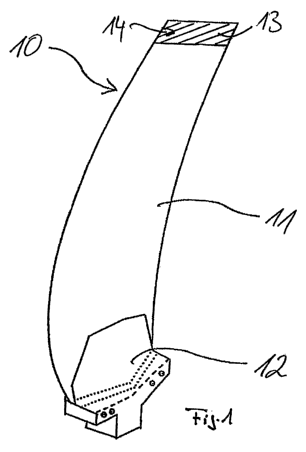
Figure I shows a schematic view of a blade having a blade tip armor plating.
In the following, the present invention is described in greater detail with
reference to
Figure I.
Figure I shows a schematized representation of a rotary blade of a high-
pressure
compressor of a gas turbine aircraft engine. Such high-pressure compressor
rotary
blades are made of a nickel base material or a nickel base alloy. Rotary blade
10
comprises a blade body 11 and a blade root 12. A radially external end of
blade body
11 forms a blade tip 13. In order to protect blade tip 13 against wear when
what is
known as blade rubbing thereof occurs in a stationary housing, said blade tip
bears a
blade tip armor plating 14 made of hard material particles or having abrasive
particles.
The present invention relates to a new method for producing such a blade tip
armor
plating 14 on a blade made of a nickel base material.
According to the present invention for producing a blade tip armor plating,
first a
blade 10 made of a nickel base material or a nickel base alloy is provided. A
nickel
base solder is applied in the area of blade tip 13 of blade body 11 of said
blade.
According to the present invention, the nickel base solder, in the fonn of a
solder film
3
CA 02613965 2007-12-31
made of a homogenous solder material, is applied to blade tip 13, preferably
by spot
welding. Subsequently, hard material particles are applied to the solder film,
namely
hard material particles of cubic boron nitride coated with titanium or with a
titanium
base material. The application of the hard material particles coated with
titanium or
with a titanium base material to the solder film takes place with the aid of a
binding
agent, preferably an organic binding agent. The coating of the hard material
particles
of cubic boron nitride with titanium or with the titanium base material
preferably
takes place using a PVD process. After the hard material particles of cubic
boron
nitride coated with titanium or with the titanium base material have been
applied to
the solder film, there takes place a fusing on of the solder at soldering
temperature in
a vacuum, in order to enclose the hard material particles at least partially
in a matrix
and to bond them securely and fixedly to blade tip 13 of rotary blade 10.
Through
cooling, there takes place a fixing of blade tip armor plating 14 on blade tip
13 of
rotary blade 10.
For the method according to the present invention for producing the blade tip
armor
plating, on the one hand it is important that a nickel base solder, preferably
in the
form of a homogenous solder film, be applied to a blade made of a nickel base
material. In addition, it is important that hard material particles of cubic
boron nitride
coated with titanium or with a titanium base material be applied to the
solder. The
titanium of the coated hard material particles forms with the cubic boron
nitride a
relatively thin titanium-nitride coating around the hard material particles,
thus
insuring a good wetting with the nickel base solder. In this way, a good
bonding of the
hard material particles of cubic boron nitride to the nickel base solder, and
thus to the
blade tip, is ensured.
4