Sélection de la langue

Search

Sommaire du brevet 2627573 

Énoncé de désistement de responsabilité concernant l'information provenant de tiers

Une partie des informations de ce site Web a été fournie par des sources externes. Le gouvernement du Canada n'assume aucune responsabilité concernant la précision, l'actualité ou la fiabilité des informations fournies par les sources externes. Les utilisateurs qui désirent employer cette information devraient consulter directement la source des informations. Le contenu fourni par les sources externes n'est pas assujetti aux exigences sur les langues officielles, la protection des renseignements personnels et l'accessibilité.

Disponibilité de l'Abrégé et des Revendications

L'apparition de différences dans le texte et l'image des Revendications et de l'Abrégé dépend du moment auquel le document est publié. Les textes des Revendications et de l'Abrégé sont affichés :

  • lorsque la demande peut être examinée par le public;
  • lorsque le brevet est émis (délivrance).
(12) Brevet: (11) CA 2627573
(54) Titre français: PROFILE DE CLOISON SECHE AVEC LANGUETTES DE REPERAGE PREPERFOREES
(54) Titre anglais: DRYWALL CHANNEL WITH PRE-PUNCHED LOCATING TABS
Statut: Accordé et délivré
Données bibliographiques
(51) Classification internationale des brevets (CIB):
  • E04B 09/22 (2006.01)
(72) Inventeurs :
  • JAHN, PETER G. (Etats-Unis d'Amérique)
  • JANKOVEC, SCOTT G. (Etats-Unis d'Amérique)
(73) Titulaires :
  • ROCKWOOL A/S
(71) Demandeurs :
  • ROCKWOOL A/S (Danemark)
(74) Agent: FINLAYSON & SINGLEHURST
(74) Co-agent:
(45) Délivré: 2010-04-13
(22) Date de dépôt: 2008-03-28
(41) Mise à la disponibilité du public: 2008-09-29
Requête d'examen: 2008-03-28
Licence disponible: S.O.
Cédé au domaine public: S.O.
(25) Langue des documents déposés: Anglais

Traité de coopération en matière de brevets (PCT): Non

(30) Données de priorité de la demande:
Numéro de la demande Pays / territoire Date
60/908,833 (Etats-Unis d'Amérique) 2007-03-29

Abrégés

Abrégé français

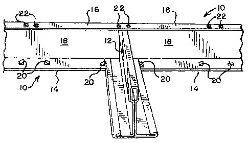
La présente demande concerne un profilé de cloison sèche possédant une forme en U ainsi que des languettes verticales qui se fixent à deux pattes horizontales. La patte horizontale inférieure est destinée à soutenir un coulisseau en T inversé possédant une âme verticale et des membrures opposées conçues pour s'appuyer sur la patte horizontale du profilé de cloison sèche. La patte horizontale inférieure est constituée d'une multitude de paires de pattes de positionnement séparées par une distance suffisante compte tenu de la largeur des membrures opposées du coulisseau en T. La patte horizontale supérieure est composée d'une multitude de paires de pattes de positionnement séparées par une distance suffisante compte tenu de la largeur du boudin de renfort du coulisseau en T.


Abrégé anglais

A wall channel for a drywall ceiling has a generally U-shaped cross-section with a vertical leg interconnecting two generally-horizontal legs. The lower horizontal leg is adapted to support an inverted tee-runner that has a vertical web and opposed flanges, the opposed flanges being adapted to rest on the horizontal leg of the wall angle. The lower horizontal leg is formed with a plurality of pairs of locating tabs that are spaced apart a distance sufficient to accommodate the width of the opposed flanges of the tee-runner. The upper horizontal leg is formed with a plurality of pairs of locating tabs that are spaced apart a distance sufficient to accommodate the width of the reinforcing bulb of the tee-runner.

Revendications

Note : Les revendications sont présentées dans la langue officielle dans laquelle elles ont été soumises.


What is claimed is:
1. A suspension system for a drywall ceiling comprising at least one inverted
tee-
runner having a vertical web, opposed horizontal flanges at a lower end of the
vertical
web, and a strengthening bulb at an upper end of the vertical web, and at
least one
channel adapted to locate and support a free end of the tee-runner, the
channel having
a generally U-shaped cross section with a vertical leg and upper and lower
generally-
horizontal legs, the horizontal legs being formed with a plurality of opposed
pairs of
tabs, the tabs in each pair on the lower leg being spaced apart a distance
sufficient to
accommodate the opposed flanges of the tee-runner, and the tabs in each pair
on the
upper leg being spaced apart a distance sufficient to accommodate the
strengthening
bulb of the tee-runner.
2. The drywall ceiling suspension system of claim 1 wherein the tee-runner has
a
vertical height, the horizontal legs of the channel having free ends that
present a vertical
opening approximately equal to the height of the tee-runner, and the vertical
leg of the
channel having a height greater than the vertical opening presented by the
legs.
3. A wall channel for a drywall ceiling having a generally U-shaped cross
section
with a vertical leg and upper and lower generally-horizontal legs, the lower
horizontal
leg being adapted to support an inverted tee-runner having a height and
comprising
vertical web, opposed flanges having a width, and a strengthening bulb, the
horizontal
legs of the channel being formed with a plurality of opposed pairs of tabs,
the tabs in
each pair on the lower leg being spaced apart a distance sufficient to
accommodate the
opposed flanges of the tee-runner, the tabs in each pair on the upper leg
being spaced
apart a distance sufficient to accommodate the strengthening bulb of the tee-
runner.
6

4. The wall channel of claim 3 wherein the horizontal legs of the channel have
free
ends that present a vertical opening approximately equal to the height of the
tee-runner,
and the vertical leg of the channel having a height greater than the vertical
opening
presented by the legs.
7

Description

Note : Les descriptions sont présentées dans la langue officielle dans laquelle elles ont été soumises.


CA 02627573 2008-03-28
DRYWALL CHANNEL WITH PRE-PUNCHED LOCATING TABS
CROSS REFERENCE TO RELATED APPLICATION
[0009] This application claims the benefit of the filing date of U.S.
Provisional
Patent Application Serial No. 60/908,833, filed March 29, 2007.
BACKGROUND
[0002] The present application is directed to a drywall channel that may be
advantageously used as part of a suspension grid or a free-span runner system
for a
drywall ceiling.
[0003] A suspension grid system for a drywall ceiling typically includes wall
angles disposed about the perimeter of the ceiling that are secured to the
walls through
their vertical legs by e.g. screws, nails, staples, and/or adhesives. The wall
angles are
typically ten feet in length and include horizontal legs or ledges to support
the ends of
the tee-shaped runners or beams. Drywall sheets are secured directly to the
bottom
sides of the horizontal flanges of the beams by screws.
SUMMARY OF THE DISCLOSURE
[0004] In one aspect of the disclosure, a wall channel or angle for a drywall
suspended ceiling is provided that has a cross-section forming a generally U-
shape with
a vertical leg and two generally horizontal legs. The horizontal legs are
adapted to
capture therebetween an inverted tee-runner that has a strengthening or
reinforcing
bead, a vertical web, and opposed flanges, the opposed flanges being adapted
to rest
on the lower horizontal leg of the wall angle.
1

CA 02627573 2008-03-28
[0005] The horizontal legs of the channel are formed with a plurality of
opposed
tabs for locating and capturing the tee-runners. The tabs may take different
forms, but
are preferably punched from the horizontal legs of the channel during a roll-
forming
operation. Two different configurations for the tabs are shown for purposes of
illustration
and not limitation.
[0006] The tabs in each pair on the lower horizontal leg are spaced apart a
distance sufficient to accommodate the width of the opposed flanges of the tee-
runner.
The tabs in each pair on the upper horizontal leg are spaced apart a distance
corresponding to the width of the reinforcing bulb of the tee-runner. The
opposed pairs
of tabs are spaced, on center, a pre-determined distance, preferably 8 inches,
which
allows an installer to space the tee-runners either 16 inches on center or 24
inches on
center, as is customary.
[0007] Other features of the disclosure will become apparent upon reference to
the following detailed description and accompanying drawings.
BRIEF DESCRIPTION OF THE DRAWINGS
[0008] Fig. 1 is a perspective view of a drywall channel and an associated tee-
runner for a suspension grid for a drywall ceiling or a suspended ceiling in
accordance
with a first embodiment of the present disclosure.
[0009] Fig 2 is a front view of the drywall channel and tee-runner shown in
Fig.1,
with the "horizontal" legs being shown straight for clarity.
[00010] Fig. 3 is an end view of the drywall channel of Figs. 1 and 2.
[00011] Fig. 4 is an enlarged fragmentary perspective view of the drywall
channel
shown in Figs. 1-3, showing the locating tabs on the lower leg.
2

CA 02627573 2008-03-28
[00012] Fig. 5 is an enlarged fragmentary perspective view of a drywall
channel of
similar to Fig. 4, but showing an alternative configuration for the locating
tabs.
DETAILED DESCRIPTION OF THE PREFERRED EMBODIMENTS
[00013] With reference to the drawings, a molding or channel, generally
designated 10, is provided for supporting the ends of the associated tee-
runners (one
such tee-runner 12 being shown in Figs. 1 and 2). The channel 10 is in the
form of a
generally U-shaped channel having spaced-apart horizontal legs 14, 16
connected by a
vertical leg 18. (While the legs 14, 16 are referred to as "horizontal," they
need only be
generally or approximately horizontal, as will become apparent below.) As best
seen in
the end view of the drywall channel 10 in Fig. 1, the upper horizontal leg 16
is shorter
than the lower horizontal leg 14, which facilitates the installation of the
tee-runners with
a downward motion. In the preferred embodiment, the upper leg 16 has a width
of
approximately 3/ inch, while the lower leg 14 has a width of approximately 1
inch.
[00014] The legs 14, 16 of the channel 10 have free ends that define or
present a
vertical opening "X" that is approximately equal to the height of the tee-
runner that is to
be received in the channel. The vertical leg 18 of the channel 10 has a height
that is
greater than x." More specifically, with reference to Fig. 1, the horizontal
legs 14, 16
are not perpendicular to the vertical leg 18, but form a slightly acute angle
with respect
thereto such that the free ends of the horizontal legs point slightly toward
each other,
with the opening "X" between the upper and lower legs 14, 16 being
approximately
equal to the height of the tee-runner 12 that is received in the channel 10
(typically
approximately 1% inches). This means that the height of the vertical leg 18 is
greater
3

CA 02627573 2008-03-28
than the height of the tee-runner, and permits the channel to receive the ends
of tee-
runners that have been distorted (i.e., vertically lengthened) when cut to
length.
Specifically, such cutting of the ends of the tee-runners creates a burr that
increases the
height of the tee-runner. The increased length of the vertical leg 18
(relative to the
height of an undistorted tee-runner) accommodates this distortion and
facilitates
installation of the tee runners. In the preferred embodiment, the upper leg 16
forms an
angle of approximately 85 degrees with respect to the vertical leg 18, while
the lower leg
14 forms an angle of approximately 86 degrees with respect to the vertical leg
18.
[00015] In keeping with another aspect of the disclosure, the horizontal legs
14, 16
are provided with pairs of regularly-spaced tabs for locating and securing the
tee
runners 12 to the wall channel 10. To this end, and with reference to Figs. 1-
4, a first
embodiment of a channel 10 is shown having a plurality of opposed, spaced
pairs of
cantilevered locating tabs 20 according to the present invention. The tabs 20
are struck
from the lower leg 14 and upper leg 16 so as to have their free ends
protruding into the
interior of the channel 10. The tabs 20 on the lower leg 14 are spaced apart a
distance
sufficient to accommodate the width of the flanges on the tee-runner, while
the tabs 20
on the upper leg 16 are spaced apart a distance sufficient to accommodate the
reinforcing bulb of the tee-runner.
[00016] Alternatively, the tabs 20 may have a D-shaped profile, as seen in
Fig. 5,
with the facing portions of the tabs forming an angle of preferably no more
than 90
degrees with respect to the leg from which they are struck, (as seen in Fig
2). The tabs
20 are formed from a straight or linear cut across horizontal leg that is
substantially
perpendicular to the vertical leg, with the cut curving or extending slightly
inwardly
4

CA 02627573 2008-03-28
toward the other tab in the pair. This results in the tabs 20 in Figs. 5
having a protruding
lip for capturing the tee-runner.
[00017] Many different configurations for the locating tabs will be apparent
to a
person skilled in the art. While the tabs on the upper and lower legs of the
channel have
been shown as having the same configuration, it is apparent that one
configuration may
be used for the tabs on the lower leg and a different configuration used for
the tabs on
the upper leg without departing from the disclosure.

Dessin représentatif
Une figure unique qui représente un dessin illustrant l'invention.
États administratifs

2024-08-01 : Dans le cadre de la transition vers les Brevets de nouvelle génération (BNG), la base de données sur les brevets canadiens (BDBC) contient désormais un Historique d'événement plus détaillé, qui reproduit le Journal des événements de notre nouvelle solution interne.

Veuillez noter que les événements débutant par « Inactive : » se réfèrent à des événements qui ne sont plus utilisés dans notre nouvelle solution interne.

Pour une meilleure compréhension de l'état de la demande ou brevet qui figure sur cette page, la rubrique Mise en garde , et les descriptions de Brevet , Historique d'événement , Taxes périodiques et Historique des paiements devraient être consultées.

Historique d'événement

Description Date
Lettre envoyée 2023-04-21
Inactive : Transferts multiples 2023-03-24
Requête pour le changement d'adresse ou de mode de correspondance reçue 2023-03-24
Représentant commun nommé 2019-10-30
Lettre envoyée 2015-02-18
Inactive : Correspondance - Transfert 2014-12-18
Lettre envoyée 2014-10-07
Accordé par délivrance 2010-04-13
Inactive : Page couverture publiée 2010-04-12
Inactive : Taxe finale reçue 2010-01-25
Préoctroi 2010-01-25
Lettre envoyée 2009-10-06
Un avis d'acceptation est envoyé 2009-10-06
Inactive : Approuvée aux fins d'acceptation (AFA) 2009-09-30
Demande publiée (accessible au public) 2008-09-29
Inactive : Page couverture publiée 2008-09-28
Inactive : CIB attribuée 2008-08-29
Inactive : CIB en 1re position 2008-08-29
Lettre envoyée 2008-05-17
Inactive : Certificat de dépôt - RE (Anglais) 2008-05-17
Demande reçue - nationale ordinaire 2008-05-17
Toutes les exigences pour l'examen - jugée conforme 2008-03-28
Exigences pour une requête d'examen - jugée conforme 2008-03-28

Historique d'abandonnement

Il n'y a pas d'historique d'abandonnement

Taxes périodiques

Le dernier paiement a été reçu le 2010-01-15

Avis : Si le paiement en totalité n'a pas été reçu au plus tard à la date indiquée, une taxe supplémentaire peut être imposée, soit une des taxes suivantes :

  • taxe de rétablissement ;
  • taxe pour paiement en souffrance ; ou
  • taxe additionnelle pour le renversement d'une péremption réputée.

Les taxes sur les brevets sont ajustées au 1er janvier de chaque année. Les montants ci-dessus sont les montants actuels s'ils sont reçus au plus tard le 31 décembre de l'année en cours.
Veuillez vous référer à la page web des taxes sur les brevets de l'OPIC pour voir tous les montants actuels des taxes.

Titulaires au dossier

Les titulaires actuels et antérieures au dossier sont affichés en ordre alphabétique.

Titulaires actuels au dossier
ROCKWOOL A/S
Titulaires antérieures au dossier
PETER G. JAHN
SCOTT G. JANKOVEC
Les propriétaires antérieurs qui ne figurent pas dans la liste des « Propriétaires au dossier » apparaîtront dans d'autres documents au dossier.
Documents

Pour visionner les fichiers sélectionnés, entrer le code reCAPTCHA :


Pour visualiser une image, cliquer sur un lien dans la colonne description du document. Pour télécharger l'image (les images), cliquer l'une ou plusieurs cases à cocher dans la première colonne et ensuite cliquer sur le bouton "Télécharger sélection en format PDF (archive Zip)" ou le bouton "Télécharger sélection (en un fichier PDF fusionné)".

Liste des documents de brevet publiés et non publiés sur la BDBC .

Si vous avez des difficultés à accéder au contenu, veuillez communiquer avec le Centre de services à la clientèle au 1-866-997-1936, ou envoyer un courriel au Centre de service à la clientèle de l'OPIC.


Description du
Document 
Date
(aaaa-mm-jj) 
Nombre de pages   Taille de l'image (Ko) 
Abrégé 2008-03-27 1 18
Description 2008-03-27 5 174
Revendications 2008-03-27 2 52
Dessins 2008-03-27 2 51
Dessin représentatif 2008-09-02 1 14
Paiement de taxe périodique 2024-03-21 42 1 748
Accusé de réception de la requête d'examen 2008-05-16 1 189
Certificat de dépôt (anglais) 2008-05-16 1 168
Avis du commissaire - Demande jugée acceptable 2009-10-05 1 162
Rappel de taxe de maintien due 2009-11-30 1 111
Correspondance 2010-01-24 1 39