Sélection de la langue

Search

Sommaire du brevet 2630313 

Énoncé de désistement de responsabilité concernant l'information provenant de tiers

Une partie des informations de ce site Web a été fournie par des sources externes. Le gouvernement du Canada n'assume aucune responsabilité concernant la précision, l'actualité ou la fiabilité des informations fournies par les sources externes. Les utilisateurs qui désirent employer cette information devraient consulter directement la source des informations. Le contenu fourni par les sources externes n'est pas assujetti aux exigences sur les langues officielles, la protection des renseignements personnels et l'accessibilité.

Disponibilité de l'Abrégé et des Revendications

L'apparition de différences dans le texte et l'image des Revendications et de l'Abrégé dépend du moment auquel le document est publié. Les textes des Revendications et de l'Abrégé sont affichés :

  • lorsque la demande peut être examinée par le public;
  • lorsque le brevet est émis (délivrance).
(12) Brevet: (11) CA 2630313
(54) Titre français: MONTAGE DE RACCORDEMENT D'ADAPTATEUR ELECTRIQUE
(54) Titre anglais: CONNECTING ARRANGEMENT OF ELECTRICAL ADAPTER
Statut: Octroyé
Données bibliographiques
(51) Classification internationale des brevets (CIB):
  • H01R 13/66 (2006.01)
  • H01R 4/28 (2006.01)
  • H01R 31/06 (2006.01)
  • H01R 13/68 (2011.01)
  • H02M 1/00 (2007.10)
  • H01R 13/68 (2006.01)
(72) Inventeurs :
  • WANG, LIEN-SHENG (Taïwan, Province de Chine)
(73) Titulaires :
  • WANG, LIEN-SHENG (Taïwan, Province de Chine)
(71) Demandeurs :
  • WANG, LIEN-SHENG (Taïwan, Province de Chine)
(74) Agent: ADE & COMPANY INC.
(74) Co-agent:
(45) Délivré: 2012-01-10
(22) Date de dépôt: 2008-04-21
(41) Mise à la disponibilité du public: 2009-10-21
Requête d'examen: 2008-04-21
Licence disponible: S.O.
(25) Langue des documents déposés: Anglais

Traité de coopération en matière de brevets (PCT): Non

(30) Données de priorité de la demande: S.O.

Abrégés

Abrégé français

Adaptateur électrique comprenant un logement muni d'une partie frontale comportant deux compartiments et deux fentes frontales, et une partie arrière comportant des encoches longitudinales et une section d'amortissement comportant deux cavités latérales, et des canaux inférieurs; deux fiches, chacune munie d'une partie arrière fixée dans la fente et le compartiment; une carte de circuits imprimés (PCB) dans le logement et comportant un transformateur; deux mains conductrices sur la partie avant de la PCB, chaque main étant fixée au compartiment; des contacts fléchis élastiquement et montés sur la partie arrière de la PCB, le contact comprenant une surface de connexion et une gorge de positionnement centrale axiale sur la surface de connexion; et un fil électrique dont la partie arrière est pliée afin de traverser le canal pour lier une cosse électrique d'extrémité de chaque conducteur respectif sur la gorge dans la cavité, et aussi de connecter électriquement ledit élément aux surfaces de connexion.


Abrégé anglais

An electrical adapter includes a housing comprising a front portion including two compartments and two front slits, and a rear portion including longitudinal slots and a damping section including two side cavities, and bottom channels; two blades each having a rear portion fastened in the slit and the compartment; a PCB in the housing and having a transformer unit; two conductive seats on a front end of the PCB, each seat being fastened in the compartment; elastically bent contacts mounted on a rear end of the PCB, the contact including a connecting surface and an axial central positioning groove on the connecting surface; and an electrical wire having its rear portion bent to pass the channel to fasten an end electrical terminal of either conductor thereof on the groove in the cavity and electrically connect same to the connecting surfaces.

Revendications

Note : Les revendications sont présentées dans la langue officielle dans laquelle elles ont été soumises.


WHAT IS CLAIMED IS:


1. An electrical adapter comprising:

a housing (10) comprising a front extending portion including two compartments

(12) and two slits (11) on a front wall of the compartment (12), and a rear
extending
portion including a plurality of longitudinal slots (13), and a damping
section (14)
extending rearward from the slots (13) and including two side cavities (141)
of
different sizes, and a plurality of bottom channels (142) open to the rear end
of the
damping section (14) and the channels (142);

two blades (82) each having a rear portion fastened in the corresponding slit
(11)
and the corresponding compartment (12);

a PCB (printed circuit board) (20) mounted in the housing (10) and having a
transformer unit (21);

two conductive seats (40) mounted on a front end of the PCB (20), each seat
(40)
being fastened in the compartment (12);

a plurality of elastically bent contacts (30) mounted on a rear end of the PCB
(20),
the contact (30) including a connecting surface (31) and an axial central
positioning
groove (311) on the connecting surface (31); and

an electrical wire (81) having its rear portion bent to pass the channel (142)
to
position an end electrical terminal (811) of either conductor thereof on the
positioning
groove (311) in the cavity (141) and electrically connect the end electrical
terminal
(811) of either conductor thereof to the connecting surfaces (31),

wherein the electrical terminals (811) are urged rearward by the contacts (30)
to
be squeezed between the positioning groove (311) and the rear end of the slot
(13).
2. The electrical adapter of claim 1, further comprising two fuses (83)
fastened on
the seats (40) and electrically connected to the seats (40) and the blades
(82).

3. The electrical adapter of claim 1, wherein the seats (40) are of concave
section.
-5-

Description

Note : Les descriptions sont présentées dans la langue officielle dans laquelle elles ont été soumises.


CA 02630313 2008-04-21

CONNECTING ARRANGEMENT OF ELECTRICAL ADAPTER
BACKGROUND OF THE INVENTION

1. Field of Invention

The invention relates to electrical adapters and more particularly to such an
electrical adapter having an improved connecting arrangement.

2. Description of Related Art

A conventional electrical adapter for, for example, a portable radio is shown
in FIG.
1. The adapter comprises a housing (not numbered), a transformer unit 6, a
plug
assembly 7 including two spaced conductive posts 71 each electrically
connected to a

blade (not numbered), two connecting elements 9 having an upper contact 91
electrically connected to one of two output terminals of the transformer unit
6, aind a
lower engaging member 91 of C-section, the engaging member 91 having a
longitudinal gap (not numbered) adapted to matingly put on the post 71, and a
bottom
plate (not numbered) threadedly secured to the housing. The adapter has the

advantages of easy assembly, easy component replacement, and without soldered
components. ,

However, the well known eiectrical adapter suffers from a disadvantage. In
detail,
the transformer unit 6 and the plug assembly 7 are required to provide with
the
engaging members 91 and the posts 71 respectively in order to effect the

engagement of the engaging members 91 with the posts 71. This can lower yield
and
greatly increase the manufacturing cost. Thus, the need for improvement still
exists.
SUMMARY OF THE INVENTION

It is therefore one object of the invention to provide an electrical adapter
comprising a housing comprising a front extending portion including two
compartments and two slits on a front wall of the compartment, and a rear
extending

portion including a plurality of longitudjnal slots, and a damping section
extending
rearward from the slots and including two cavities of different sizes open to
the sides,
-i- -


CA 02630313 2008-04-21

and a plurality of bottom channels open to the rear end of the damping section
and the
channels; two blades each having a rear portion fastened in the corresponding
slit and
the corresponding compartment; a PCB mounted in the housing and having a
transformer unit; two conductive seats mounted on a front end of the PCB, each
seat

being fastened in the compartment; a plurality of elastically bent contacts
mounted on
a rear end of the PCB, the contact including a connecting surface and an axial
central
positioning groove on the connecting surface; and an electrical wire having
its rear
portion bent to pass the channel to position an end electrical terminal of
either
conductor thereof on the positioning gr6ove in the cavity and electrically
connect the

end electrical terminal of either conductor thereof to the connecting
surfaces, wherein
the electrical terminals are urged rearward by the contacts to be squeezed
between
the positioning groove and the rear end of the slot.

The above and other objects, features and advantages of the invention will
become apparent from the following detailed description taken with the
accompanying
drawings.

BRIEF DESCRIPTION OF THE DRAWINGS

FIG. I is an exploded view of a conventional electrical adapter;

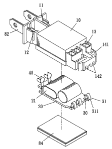
FIG. 2 is an exploded view of a preferred embodiment of electrical adapter
according to the invention;

FIG. 3 is a top plan view of the assembled electrical adapter of FIG. 2;

FIG. 4 is a side elevation in part section of the electrical adapter of FIG.
3; and
FIG. 5 is a view similar to FIG. 4 showing the electrical wire being secured
to the
contacts by bending to pass the damping section.

DETAILED DESCRIPTION OF THE INVENTION

Referring to FIGS. 2 to 5, an electrical adapter in accordance with a
preferred
embodiment of the invention comprises a housing 10 including a front portion
including two compartments 12 divided by a wall, and two slits 11 each formed
on a
-2-


CA 02630313 2008-04-21

front wall of the compartment 12. Either blade 82 has a rear portion fastened
in the slit
11 and the compartment 12 of the same side.

The adapter further comprises a PCB (printed circuit board) 20 including an
electrical component (e.g., transformer unit) 21 mounted thereon. The PCB 20
is
mounted within the housing 10. A bottom plate 84 is mounted at the bottom of
the

housing 10 to fasten the PCB 20 in the housing 10. Two copper seats 40 of
concave
section are mounted on a front end of the PCB 20. The seats 40 are fastened in
the
compartments 12 respectively. Further, two fuses 83 are fastened on the seats
40 and
are electricaliy connected to both the seats 40 and the blades 82.

The adapter further comprises a series of (three) elastically bent contacts 30
mounted on a rear end of the PCB 20. The contact 30 comprises a connecting
surface
31 facing rear and an axial central posiiioning groove 311 on the connecting
surface
31.

The housing 10 further comprises a rear portion including three spaced slots
13
open to both top and bottom, and a damping section 14 extending rearward from
the
slots 13 and including two cavities 141 of different sizes open to the sides,
and a
series of bottom channels 142 in the rear end of the damping section 14, the
channels
142 being in communication with the cavities 141.

The adapter further comprises an electrical wire 81 having its rear portion
bent to
pass the channel 142 to position an end electrical terminal 811 of either
conductor
thereof on the groove 311 of the connecting surface 31 in the cavity 141. As
shown in
FIG. 5, the electrical terminal 811 is urged rearward by the contact 30 to be
squeezed
between the groove 311 and the rear wall of the slot 13. Thus, the electrical
terminals
811 are reliably electrically connected to the connecting surfaces 31. It is

contemplated by the invention that a pulling of the electrical wire 81 will
not easily
disengage the electrical wire 81 from the contacts 30.

While the invention herein disclosed has been described by means of specific
-3-


CA 02630313 2008-04-21

embodiments, numerous modifications and variations could be made thereto by
ttiose
skilled in the art without departing from the scope and spirit of the
invention set forth in
the claims.

-4-

Dessin représentatif
Une figure unique qui représente un dessin illustrant l'invention.
États administratifs

Pour une meilleure compréhension de l'état de la demande ou brevet qui figure sur cette page, la rubrique Mise en garde , et les descriptions de Brevet , États administratifs , Taxes périodiques et Historique des paiements devraient être consultées.

États administratifs

Titre Date
Date de délivrance prévu 2012-01-10
(22) Dépôt 2008-04-21
Requête d'examen 2008-04-21
(41) Mise à la disponibilité du public 2009-10-21
(45) Délivré 2012-01-10

Historique d'abandonnement

Il n'y a pas d'historique d'abandonnement

Taxes périodiques

Dernier paiement au montant de 236,83 $ a été reçu le 2023-10-19


 Montants des taxes pour le maintien en état à venir

Description Date Montant
Prochain paiement si taxe applicable aux petites entités 2025-04-21 253,00 $
Prochain paiement si taxe générale 2025-04-21 624,00 $

Avis : Si le paiement en totalité n'a pas été reçu au plus tard à la date indiquée, une taxe supplémentaire peut être imposée, soit une des taxes suivantes :

  • taxe de rétablissement ;
  • taxe pour paiement en souffrance ; ou
  • taxe additionnelle pour le renversement d'une péremption réputée.

Les taxes sur les brevets sont ajustées au 1er janvier de chaque année. Les montants ci-dessus sont les montants actuels s'ils sont reçus au plus tard le 31 décembre de l'année en cours.
Veuillez vous référer à la page web des taxes sur les brevets de l'OPIC pour voir tous les montants actuels des taxes.

Historique des paiements

Type de taxes Anniversaire Échéance Montant payé Date payée
Requête d'examen 400,00 $ 2008-04-21
Le dépôt d'une demande de brevet 200,00 $ 2008-04-21
Taxe de maintien en état - Demande - nouvelle loi 2 2010-04-21 50,00 $ 2010-03-09
Taxe de maintien en état - Demande - nouvelle loi 3 2011-04-21 50,00 $ 2011-03-04
Taxe finale 150,00 $ 2011-10-17
Taxe de maintien en état - brevet - nouvelle loi 4 2012-04-23 50,00 $ 2012-04-02
Taxe de maintien en état - brevet - nouvelle loi 5 2013-04-22 100,00 $ 2013-03-15
Taxe de maintien en état - brevet - nouvelle loi 6 2014-04-22 100,00 $ 2014-04-17
Taxe de maintien en état - brevet - nouvelle loi 7 2015-04-21 100,00 $ 2015-02-12
Taxe de maintien en état - brevet - nouvelle loi 8 2016-04-21 100,00 $ 2016-03-04
Taxe de maintien en état - brevet - nouvelle loi 9 2017-04-21 200,00 $ 2017-03-29
Taxe de maintien en état - brevet - nouvelle loi 10 2018-04-23 250,00 $ 2018-03-28
Taxe de maintien en état - brevet - nouvelle loi 11 2019-04-23 250,00 $ 2019-03-27
Taxe de maintien en état - brevet - nouvelle loi 12 2020-04-21 250,00 $ 2020-04-01
Taxe de maintien en état - brevet - nouvelle loi 13 2021-04-21 255,00 $ 2021-03-31
Taxe de maintien en état - brevet - nouvelle loi 14 2022-04-21 254,49 $ 2022-03-09
Taxe de maintien en état - brevet - nouvelle loi 15 2023-04-21 236,83 $ 2023-02-14
Taxe de maintien en état - brevet - nouvelle loi 16 2024-04-22 236,83 $ 2023-10-19
Titulaires au dossier

Les titulaires actuels et antérieures au dossier sont affichés en ordre alphabétique.

Titulaires actuels au dossier
WANG, LIEN-SHENG
Titulaires antérieures au dossier
S.O.
Les propriétaires antérieurs qui ne figurent pas dans la liste des « Propriétaires au dossier » apparaîtront dans d'autres documents au dossier.
Documents

Pour visionner les fichiers sélectionnés, entrer le code reCAPTCHA :


Pour visualiser une image, cliquer sur un lien dans la colonne description du document. Pour télécharger l'image (les images), cliquer l'une ou plusieurs cases à cocher dans la première colonne et ensuite cliquer sur le bouton "Télécharger sélection en format PDF (archive Zip)" ou le bouton "Télécharger sélection (en un fichier PDF fusionné)".

Liste des documents de brevet publiés et non publiés sur la BDBC .

Si vous avez des difficultés à accéder au contenu, veuillez communiquer avec le Centre de services à la clientèle au 1-866-997-1936, ou envoyer un courriel au Centre de service à la clientèle de l'OPIC.


Description du
Document 
Date
(yyyy-mm-dd) 
Nombre de pages   Taille de l'image (Ko) 
Abrégé 2008-04-21 1 21
Description 2008-04-21 4 140
Revendications 2008-04-21 1 42
Dessins 2008-04-21 5 67
Dessins représentatifs 2009-09-23 1 11
Page couverture 2009-10-15 2 47
Page couverture 2011-12-13 2 46
Correspondance 2008-06-10 1 62
Cession 2008-04-21 5 130
Correspondance 2011-09-15 1 13
Correspondance 2009-12-22 1 38
Correspondance 2010-01-11 1 88
Poursuite-Amendment 2011-08-26 5 146
Correspondance 2011-09-15 1 79
Correspondance 2010-10-04 1 63
Correspondance 2011-10-17 2 65