Note : Les descriptions sont présentées dans la langue officielle dans laquelle elles ont été soumises.
CA 02633919 2008-06-11
WO 2007/069029 PCT/IB2006/003563
-1-
PCBN CUTTING TOOL COMPONENTS
BACKGROUND OF THE INVENTION
This invention relates to ultra-hard cutting tool components and more
particularly PCBN cutting tool components.
Boron nitride exists typically in three crystalline forms, namely cubic boron
nitride (CBN), hexagonal boron nitride (hBN) and wurtzitic cubic boron
nitride (wBN). Cubic boron nitride is a hard zinc blend form of boron nitride
that has a similar structure to that of diamond. In the CBN structure, the
bonds that form between the atoms are strong, mainly covalent tetrahedral
bonds.
CBN has wide commercial application in machining tools and the like. It
may be used as an abrasive particle in grinding wheels, cutting tools and
the like or bonded to a tool body to form a tool insert using conventional
electroplating techniques.
CBN may also be used in bonded form as a CBN compact, also known as
PCBN (polycrystalline CBN). CBN compacts comprise sintered masses of
CBN particles. When the CBN content exceeds 80 percent by volume of
the compact, there is a considerable amount of CBN-to-CBN contact.
When the CBN content is lower, e.g. in the region of 40 to 60 percent by
CA 02633919 2008-06-11
WO 2007/069029 PCT/IB2006/003563
-2-
volume of the compact, then the extent of direct CBN-to-CBN contact is
limited.
CBN compacts will generally also contain a binder containing one or more
ceramic phase(s) in compacts containing aluminium, cobalt, nickel,
tungsten and titanium.
CBN compacts tend to have good abrasive wear, are thermally stable, have
a high thermal conductivity, good impact resistance and have a low
coefficient of friction when in contact with a workpiece. The CBN compact,
with or without substrate, is often cut into the desired size and/or shape of
the particular cutting or drilling tool to be used and then mounted on to a
tool body utilising brazing techniques.
When the CBN content of the compact is less than 70 percent by volume,
the matrix phase, i.e. the non-CBN phase, will typically also comprise an
additional or secondary hard phase, which may be ceramic in nature.
Examples of suitable ceramic hard phases are carbides, nitrides, borides
and carbonitrides of a Group 4, 5 or 6 (according to the new IUPAC
format) transition metal aluminium oxide and mixtures thereof. The matrix
phase constitutes all the ingredients in the composition excluding CBN.
CBN compacts may be bonded directly to a tool body in the formation of a
tool insert or tool. However, for many applications it is preferable that the
compact is bonded to a substrate/support material, forming a supported
compact structure, and then the supported compact structure is bonded to
a tool body. The substrate/support material is typically a cemented metal
carbide that is bonded together with a binder such as cobalt, nickel, iron or
a mixture or alloy thereof. The metal carbide particles may comprise
tungsten, titanium or tantalum carbide particles or a mixture thereof.
A known method for manufacturing the polycrystalline CBN compacts and
supported compact structures involves subjecting an unsintered mass of
CBN particles together with a powdered matrix phase, to high temperature
CA 02633919 2008-06-11
WO 2007/069029 PCT/IB2006/003563
-3-
and high pressure conditions, i.e. conditions at which the CBN is
crystallographically or thermodynamically stable, for a suitable time period.
Typical conditions of high temperature and pressure which are used are
temperatures in the region of 1100 C or higher and pressures of the order
of 2 GPa or higher. The time period for maintaining these conditions is
typically about 3 to 120 minutes.
CBN compacts with CBN content more than 70 volume percent are known
as high CBN PCBN materials. They are employed widely in the
manufacture of cutting tools for machining of grey cast irons, white cast
irons, powder metallurgy steels, tool steels and high manganese steels. In
addition to the conditions of use, such as cutting speed, feed and depth of
cut, the performance of the PCBN tool is generally known to be dependent
on the geometry of the workpiece and in particular, whether the tool is
constantly engaged in the workpiece for prolonged periods of time, known
in the art as "continuous cutting", or whether the tool engages the
workpiece in an intermittent manner, generally known in the art as
"interrupted cutting".
Commercially available PCBN cutting tools all have sintered PCBN layers
with thicknesses above 0.2 mm. These thick PCBN layers are difficult and
expensive to process. The cost of manufacture of a PCBN cutting tool has
thus made it too expensive to compete successfully in the carbide cutting
tool market. For PCBN to be considered for typical carbide applications, it
has to be easier and cheaper to process and have higher chip resistance,
while still outperforming carbide in terms of wear resistance.
US patent no. 5,697,994 describes a cutting tool for woodworking
applications comprising a layer of PCD or PCBN on a cemented carbide
substrate. The PCD is generally provided with a corrosion resistant or
oxidation resistant adjuvant alloying material in the bonding phase. An
example is provided wherein the PCD layer is 0.3mm in thickness. For
PCBN the layer thickness is preferably 0.3 to 0.9 mm.
CA 02633919 2008-06-11
WO 2007/069029 PCT/IB2006/003563
-4-
SUMMARY OF THE INVENTION
A cutting tool component of the invention comprises a body comprising a
cemented carbide substrate and having at least one working surface, the at
least one working surface presenting a cutting edge or area for the body,
characterized in that the at least one working surface comprises PCBN
adjacent the cutting edge or area and extending to a depth of no greater
than 0.2 mm from the at least one working surface and wherein the
substrate has a thickness of 1.0 to 40 mm.
In one preferred embodiment of the invention, the cutting tool component
body comprises a cemented carbide substrate and an ultra-thin layer of
PCBN bonded to a major surface of the substrate, the ultra-thin layer of
PCBN having a thickness of no greater than, generally less than, 0.2 mm
and the substrate has a thickness between 1.0 to 40 mm .
In an alternative preferred embodiment of the invention, one or more
intermediate layers is/are located between the cemented carbide substrate
and the layer of PCBN, preferably based on a ceramic, metal or ultra-hard
material or combination thereof that is softer than the PCBN.
In another alternative preferred embodiment of the invention, the cutting
tool component body comprises a cemented carbide substrate having a
working surface presenting a cutting edge or area for the tool component
and having a plurality of grooves or recesses extending into the substrate
from the working surface, and a plurality of strips or pieces of ultra-hard
material located in the respective grooves or recesses, the arrangement
being such that the PCBN extends to a depth of no greater than 0.2 mm
from the working surface and forms a part of the cutting edge or area of the
tool component.
The thickness or depth of the PCBN layer or inserts is preferably from
0.001 to 0.15 mm.
CA 02633919 2008-06-11
WO 2007/069029 PCT/IB2006/003563
-5-
The PCBN optionally contains a second phase comprising a metal or metal
compound selected from the group comprising aluminium, cobalt, iron,
nickel, platinum, titanium, chromium, tantalum, copper, tungsten or an alloy
or mixture thereof.
BRIEF DESCRIPTION OF THE DRAWINGS
The invention will now be described in more detail, by way of example only,
with reference to the accompanying drawings in which:
Figure 1 is a partial perspective view of a first embodiment of a
cutting tool component of the invention:
Figure 2 is a partial perspective view of a second embodiment of a
cutting tool component of the invention:
Figure 3 is a partial perspective view of a third embodiment of a
cutting tool component of the invention:
Figure 4 is a schematic side view of a cutting tool component of the
invention in use, illustrating the "self-sharpening" effect
thereof;
Figure 5 is a graph showing chip size under light interrupted
machining conditions for two PCBN cutting tools; and
Figure 6 is a box plot illustrating fracture resistance for two PCBN tool
cutting tools.
CA 02633919 2008-06-11
WO 2007/069029 PCT/IB2006/003563
-6-
DESCRIPTION OF PREFERRED EMBODIMENTS
The object of the present invention is to provide an engineered PCBN
cutting tool with properties between cemented carbide and PCBN.
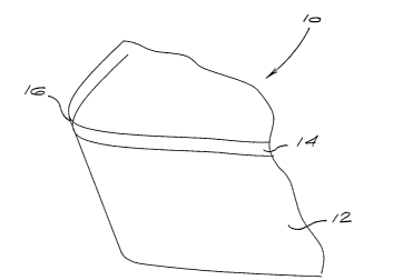
The object is addressed by providing a cutting tool component 10, as
illustrated for example in Figure 1, which comprises a cemented carbide
substrate 12 with an ultra-thin layer 14 of PCBN, which has a thickness of
no greater than, generally less than 0.2 mm, preferably between 0.001 -
0.15 mm and wherein the substrate has a thickness from 1.0 - 40 mm.
Such a cutting tool component is produced by high temperature high
pressure synthesis. The thickness of the ultra-thin hard layer 14 at the
cutting edge 16 is the critical parameter determining the properties of the
material and allows for cutting with both the top hard layer 14 (PCBN) and
the carbide substrate 12. Wear resistance, chip resistance, cutting forces,
grindability, EDM ability and thermal stability are all properties affected by
the thickness of the hard layer. Various methods for producing PCBN
cutting tools with cemented carbide substrates exist and are well known in
the industry.
The ultra-thin hard layer together with the softer substrate results in a
"self-
sharpening" behaviour during cutting, which in turn reduces the forces and
temperatures at the cutting edge. The hard layer is a high or low CBN
content PCBN, of the type described above. The thickness of the hard
layer preferably varies between 0.001-0.15 mm, depending on the required
properties for specific applications.
Referring to the tool component 30 of Figure 2, the ultra-thin hard layer 32
can also be bonded to an intermediate softer layer 34 of metal, ceramic, or
ultra-hard material which in turn is bonded to the cemented carbide
substrate 36.
Alternatively, referring to the tool component 40 as illustrated in Figure 3,
the ultra-thin hard layer may also be in the form of strips 42 (vertical
layers)
CA 02633919 2008-06-11
WO 2007/069029 PCT/IB2006/003563
-7-
across the cutting tool alternating with the substrate material 44, where the
width 46 of the strips is between 10 and 50 microns. Other arrangements
where recessed pieces of PCBN are located in the substrate material are
also envisaged.
The substrate material can be selected from tungsten carbides, ultra-fine
grain tungsten carbides, titanium carbides, tantalum carbides and niobium
carbides. Methods for producing cemented carbides are well known in the
industry. Because cutting is done with both the PCBN and the carbide, the
selection of the substrate is another variable which can be changed in order
to alter the properties of the cutting element to suit different applications.
In some applications, it may be preferable to provide a substrate having a
profiled or shaped surface, which results in an interface with a
complimentary shape or profile.
From a processability perspective the critical feature of the invention is the
ultra-thin hard layer which will reduce the processing cost of PCBN cutting
tools.
In terms of performance the critical feature of the invention is to adjust the
hard layer thickness so that the desired properties can be achieved and
also to ensure that a "self-sharpening" effect takes place during cutting.
This could mean adding a softer ceramic or metal intermediate layer just
below the PCBN. This means that when the wear progresses through the
hard layer at some stage during the cutting process, the cutting will be done
by both the hard layer and the substrate and/or the intermediate layer.
Conventional tools all have a hard layer thickness above 0.2 mm, and
hence the substrate never comes in contact with the workpiece (since tool
life criteria is VBBmax = 0.2 - 0.3 mm) and the properties and behaviour of
the tool is that of the hard layer only.
As illustrated in Figure 4, as long as cutting is done by the hard layer 14,
the wear rate will be that of the hard layer. As soon as the wear extends
CA 02633919 2008-06-11
WO 2007/069029 PCT/IB2006/003563
-8-
into the carbide substrate 12 and the cutting is done by both the PCBN and
the carbide, the wear rate will increase to include both that of the substrate
and of the hard layer. Thus, the thicker the hard layer, the longer the wear
rate is controlled by the wear resistance of the hard layer and the longer the
tool life. Having an ultra-thin hard layer where the cutting is done by both
the hard layer and the carbide gives a wear resistance between that of
carbide and the hard layer. By varying the thickness of the hard layer
(between 0.001 - 0.15 mm) it allows one to change the properties and the
tool life of the material to what is required for a specific application. This
allows one to provide signature products for specific applications. The
thinner the hard layer, the closer the cutting tool properties will be to that
of
the substrate. However, due to the "self-sharpening" effect of the
engineered cutting tool, the cutting process and wear rate are dominated by
the hard layer.
A major benefit of cutting with both the ultra-thin hard layer 14 and the
substrate 12 is the "self-sharpening" effect it has on the tool. As
illustrated
in Figure 4, it can be seen that because the material of the substrate 12 is
much softer than the top hard layer 14, it wears away quicker than the hard
layer 14, forming a "lip" 18 between the hard layer and the bottom layer at
the edge 16. This allows the tool to cut predominantly with the top hard
layer 14, minimising the contact area with the workpiece which ultimately
results in lower forces and temperatures at the cutting edge 16. It also
means that when the tool wears it keeps a clearance angle (a) allowing it to
cut more efficiently. This wear behaviour is ideal for roughing applications
and wood composite machining, especially in saw blade applications,
where dimensional tolerances are not so critical. It is also beneficial in oil
drilling applications where a sharp cutter results in a lower "weight on bit"
and higher penetration rates. It will also be beneficial in the machining of
ferrous materiais.
Another benefit of ultra-thin hard layers is the improved chip resistance it
gives to the tool. Thicker layers have higher residual stresses and are more
susceptibie to chipping and fracture. Also, if chipping does occur, the
CA 02633919 2008-06-11
WO 2007/069029 PCT/IB2006/003563
-9-
carbide substrate will arrest the crack and stop it from getting bigger than
the thickness of the top hard layer.
Effect on Processability
All processing (EDM, EDG, grinding) is easier and faster as the top hard
layer becomes thinner. Having ultra-thin hard layers will shorten processing
times. .
As explained earlier conventional PCBN compacts are manufactured with
PCBN layer thicknesses > 0.2 mm in order for the cutting to be done by the
hard layer only. However, during the synthesis of such thick layers, the
compact often bows because of the thermal expansion differences between
that of PCBN and the carbide substrate. This results in additional
processing (mechanical grinding, EDG or lapping) to get the compact back
to flatness. With ultra-thin hard layers, bending of the disc is minimised and
additional processing is not required. This allows for the production of near-
net shape PCBN compacts.
The invention will now further be discussed, by way of example only, with
reference to the following non-limiting examples. These examples show
the advantages of an ultra-thin PCBN cutting tool component. The PCBN
cutting tool components used in the examples were made by PCBN
manufacturing methods well known in the art and as described above.
Example 1: AIS14340 'drilled' light interrupted machining test
The test is believed to be very representative of hard machining. Two
PCBN cutting tool components of the type described above were used in
the test. The one had an ultra-thin PCBN layer 0.1 mm in thickness and
the other a PCBN layer of 0.5 mm thickness. The maximum chip size was
recorded. The test conditions were as follows:
CA 02633919 2008-06-11
WO 2007/069029 PCT/IB2006/003563
-10-
Feed, f Depth of Cutting Insert
Test (mm) cut, ap Speed, vc
Geometry
(mm) (m/min)
(AISI) 4340
Drilled 0.15 0.2 150 SNMN090308
Face- S0220
Turning
From the graph of Figure 5 it can be seen that the ultra-thin PCBN exhibits
less fracture than the thicker 0.5 mm layer. As was the case with PCD the
actual chip on the edge gets "arrested" once the fracture path reaches the
carbide. From there onwards wear is the critical feature and not fracture.
Example 2: Roughing example: Catastrophic fracture resistance
machining compact graphite cast Iron (CGI)
An interrupted milling operation was performed using the same two PCBN
cutting tool components of Example 1 whereby the conditions and
workpiece were chosen as to minimise any wear events and in return
promote fracture. The feed per tooth was increased from 0.1 to 0.2 to 0.3
etc until catastrophic failure of the nose was observed. The feed per tooth
represent the load on the cutting edge and is therefore a suitable fracture
resistance indicator. The test conditions that were used are as follow:
- Workpiece material: GJV 400 (>95% Pearlite, 10% nodularity)
- Cutting Speed: 300 m/min
- Feed per tooth: varied
- DOC: 1 mm
- WOC: '/z the block
- Relief angle: 18 deg
- Rake angle: Odeg
From the Box-plot of Figure 6 it appears that the 01 layer has a higher
fracture resistance than the 05 layer. Since this data is not normally
CA 02633919 2008-06-11
WO 2007/069029 PCT/IB2006/003563
-11-
distributed, a Kruskal-Wallis Statistical test was performed in order to
evaluate whether this improvement is significant. Since the P-value is
smaller than 0.05 it can be concluded that the thin layer is significantly
more fracture resistant than the 0.5 mm layer
Kruskal-Wallis Test: Fz failure versus Tool material
Kruskal-Wallis Test on Fz failure
Tool Ave
Material N Median Rank z
PCBNO1 5 0.5000 7.5 2.09
PCBNO5 5 0.3000 3.5 -2.09
Overall 10 5.5
H=4.36 DF=1 P = 0.037
H = 4.50 DF = 1 P = 0.034 (adjusted for ties)