Note : Les descriptions sont présentées dans la langue officielle dans laquelle elles ont été soumises.
CA 02634569 2008-06-10
APPARATUS FOR CARRYING MULTIPLE FISHING POLES
FIELD OF THE INVENTION
This invention relates to the field of fishing and more
particularly to a device for organizing multiple fishing poles
while transporting the same.
BACKGROUND OF THE INVENTION
A fisherman rarely carries one rod and reel to his or her
place of fishing. Rather, several rods and reels are carried
along with assorted fishing tackle. Carrying multiple rods and
reels of varying lengths and diameters is often a difficult
task being that each rod tends to go in a different direction.
A solution to this problem is presented in US Pat. No.
3,113,363 to Fyvie. This patent includes disks into which the
fishing poles are snapped and held by friction. The disks of
this patent need be made to accommodate specific rod
diameters. Furthermore, the disks of this patent are not
connected to each other and will allow the rods to twist
within the disk apertures.
Another solution is presented in US Pat. No. 4,628,628 to
Burgin et al. This patent also includes disks with apertures
for accepting the rods, but each aperture is also sized to the
1
CA 02634569 2008-06-10
diameter of the rods and there is no provision to secure the
rods into the apertures.
Another solution is presented in US Pat. No. 5,450,688 to
l:fall. This patent also has disks with apertures for holding
the rods but is intended for carrying rods in their two-piece
state and has no provision for strapping the rods securely to
the disks.
Another solution is presented in US Pat. No. 5,678,348 to
Zielinski, et al. This patent has disks with apertures for
holding the rods. This patent has retaining straps that
encircle the disks to retain the rods, but has no rigid member
connecting the disks to each other, thereby allowing the disks
to randomly rotate.
Another solution is presented in US Pat. No. 6,471,103 to
Frese, et al. This patent has disks with apertures for holding
the rods. This patent has a rigid member connecting the disks
to each other but does not have a positive way to retain
fishing poles of various sizes to the disks.
What is needed is a carrier for multiple fishing poles
that will also organize the rods and prevent them from
tangling.
2
CA 02634569 2008-06-10
SUMMARY OF THE INVENTION
In one embodiment, an apparatus for carrying multiple
fishing poles is disclosed including a connecting rod with a
first end and a distal second end and a first supporting
rnember affixed to the first end of the connecting rod and a
second supporting member affixed to the distal end of the
connecting rod. A plurality of recesses is in the supporting
rnembers, each of the recesses sized to accept one of the
fishing poles. A first cloth strap is affixed at one end to
the first supporting member and adapted to removably cover the
outer circumference of the first supporting member, thereby
r_emovably holding the fishing poles within the recesses of the
first supporting member and a second cloth strap is affixed at
one end to the second supporting member and adapted to
removably cover the outer circumference of the second
supporting member, thereby removably holding the fishing poles
within the recesses of the second supporting member.
In another embodiment, a method of carrying multiple
fishing poles is disclosed including providing an apparatus
for carrying multiple fishing poles that has a connecting rod
with a first end and a distal second end. A first supporting
niember is affixed to the first end of the connecting rod and a
second supporting member is affixed to the distal end of the
connecting rod. A plurality of recesses is formed in the
3
CA 02634569 2008-06-10
supporting members, each of the recesses sized to accept one
of the fishing poles. A first cloth strap is affixed at one
end to the first supporting member and adapted to removably
cover the outer circumference of the first supporting member,
thereby removably holding the fishing poles within the
recesses of the first supporting member and a second cloth
strap is affixed at one end to the second supporting member
and adapted to removably cover the outer circumference of the
second supporting member, thereby removably holding the
fishing poles within the recesses of the second supporting
nlember. The method continues with placing at least one fishing
pole into the recesses of the first supporting member and
placing the at least one fishing pole into a corresponding
recesses of the second supporting member then affixing the
first cloth strap around the first supporting member and
affixing the second cloth strap around the second supporting
member thereby securing the at least one fishing pole to the
first supporting member and the second supporting member. The
niethod completes with carrying the at least one fishing pole
by holding one of the at least one fishing poles.
In another embodiment, an apparatus for carrying multiple
fishing poles is disclosed including a first device for
holding the fishing poles that has a first plurality of
recesses on its peripheral surface and has a first device for
4
CA 02634569 2008-06-10
removably securing the fishing pole into its recesses. A
similar device for holding fishing poles has a second
plurality of recesses on its peripheral surface and the second
device for removably securing the fishing poles into its
recesses. The first device for holding the fishing poles is
connected to the second device for holding the fishing poles
by a rigid support.
BRIEF DESCRIPTION OF THE DRAWINGS
The invention can be best understood by those having
ordinary skill in the art by reference to the following
detailed description when considered in conjunction with the
accompanying drawings in which:
FIG. 1A illustrates a schematic view of a fishing rod
holder with multiple fishing poles of a first embodiment of
the present invention.
FIG. 1B illustrates a schematic view of a fishing rod
holder with multiple fishing poles of a second embodiment of
the present invention.
FIG. 2 illustrates an isometric view of a supporting
niember of all embodiments of the present invention.
5
CA 02634569 2008-06-10
FIG. 3 illustrates an isometric view of a supporting
member of all embodiments of the present invention engaged
with a plurality of fishing poles.
FIGS. 4A through 4E illustrate isometric views of
alternate supporting members of all embodiments of the present
invention.
FIG. 5 illustrates a front view of another alternate
supporting members of all embodiments of the present
invention.
FIG. 6 illustrates an isometric view of the present
invention.
DETAILED DESCRIPTION OF THE INVENTION
Reference will now be made in detail to the presently
preferred embodiments of the invention, examples of which are
illustrated in the accompanying drawings. Throughout the
following detailed description, the same reference numerals
refer to the same elements in all figures.
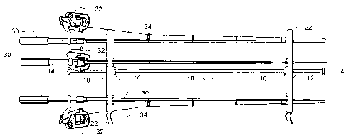
Referring to FIG. 1A, a schematic view of a fishing rod
holder with multiple fishing poles of a first embodiment of
the present invention will be described. In this embodiment,
two supporting members 10/12 are securely held to each other
by a connecting rod 18. In some embodiments, the supporting
6
CA 02634569 2008-06-10
members 10/12 are fastened to the connecting rod 18 at a fixed
location. In the example shown, the supporting members 10/12
are restrained on the connecting rod 18 by stops 14/16,
allowing an adjustment of the supporting members 10/12 between
the first stop 14 and the second stop 16. In this embodiment,
if a feature of one of the fishing poles 30 (e.g., a fishing
line guide) align with the supporting members 10/12, the
supporting members 10/12 are relocatable to a position where
the feature no longer interferes with the supporting members
10/12. In the example shown, three fishing poles 30 with reels
32 and fishing line 34 are shown for completeness.
To securely hold the fishing poles 30 to the support
members 10/12, a securable band of material 22 removable
secures around the circumference of each support member 10/12.
In the preferred embodiment, the securable band of material 22
is made from cloth (e.g., nylon). One end of the securable
band of material 22 is affixed to the circumference of each
support member 10/12 and the loose end of the securable band
of material 22 has hook and loop material on its inside
surface, adapted to affix the loose end to matching hook and
loop material on the outside surface of the securable band of
nlaterial 22. In alternate embodiments, the loose end of the
securable band of material 22 is removably affixed to itself
7
CA 02634569 2008-06-10
by ways known in the industry including, but not limited to
snaps, buckles, buttons and clips.
In some embodiments, the supporting members 10/12 freely
slide within a restricted area of the connecting rod 18 while
in other embodiments, the supporting members 10/12 are fixed
in position on a threaded portion of the connecting rod 18 by
fasteners 16 such as nuts. In some embodiments, the supporting
members 10/12 freely rotate on the connecting rod 18 while in
other embodiments, supporting members 10/12 are kept from
rotating on the connecting rod 18.
The connecting rod 18 is made from any suitable stiff
material such as steel, wood and hard plastic. The supporting
members 10/12 are made from any suitable stiff material such
as steel, wood, plastic, metal, etc. In some embodiments, it
is preferred that the supporting members 10/12 be made from a
stiff, yet slightly flexible plastic such as low density
polypropylene (LDPE) and nylon.
Referring to FIG. 1B, a schematic view of a fishing rod
holder with multiple fishing poles of a second embodiment of
the present invention will be described. In this embodiment,
two supporting members 10/12 are securely held to each other
by a shortened connecting rod 18. In some embodiments, the
supporting members 10/12 are fastened to the connecting rod 18
8
CA 02634569 2008-06-10
at a fixed location. In the example shown, the supporting
members 10/12 are restrained on the connecting rod 18 by stops
14/16, allowing an adjustment of the supporting members 10/12
between the first stop 14 and the second stop 16. In this
embodiment, if a feature of one of the fishing poles 30 (e.g.,
a fishing line guide) align with the supporting members 10/12,
the supporting members 10/12 are relocatable to a position
where the feature no longer interferes with the supporting
niembers 10/12. In the example shown, three fishing poles 30
with reels 32 and fishing line 34 are shown for completeness.
The supporting members 10/12 slidably interface with the
connecting rod 18.
As in the first embodiment, to securely hold the fishing
poles 30 to the support members 10/12, a securable band of
material 22 removable secures around the circumference of each
support member 10/12. In the preferred embodiment, the
securable band of material 22 is made from cloth (e.g.,
nylon). One end of the securable band of material 22 is
affixed to the circumference of each support member 10/12 and
the loose end of the securable band of material 22 has hook
and loop material on its inside surface, adapted to affix the
loose end to matching hook and loop material on the outside
surface of the securable band of material 22. In alternate
embodiments, the loose end of the securable band of material
9
CA 02634569 2008-06-10
22 is removably affixed to itself by ways known in the
industry including, but not limited to snaps, buckles,
buttons, a sticky surface and clips. The supporting members
10/12 slidably interface with the connecting rod 18. In some
embodiments, the supporting members 10/12 freely slide within
a restricted area of the connecting rod 18 while in other
embodiments, the supporting members 10/12 are fixed in
position on a threaded portion of the connecting rod 18 by
fasteners 16 such as nuts. In some embodiments, the supporting
members 10/12 freely rotate on the connecting rod 18 while in
other embodiments, supporting members 10/12 are kept from
rotating on the connecting rod 18.
Referring to FIG. 2, an isometric view of a supporting
member of all embodiments of the present invention will be
described. In this example, the supporting member 10 has
recesses 20 for holding up to three fishing poles 30. It is
preferred that the recesses 20 be of greater diameter than the
largest anticipated fishing pole 30. Nothing limits the
recesses 20 from being of varying diameters and sizes. A hole
15 in the center accepts the connecting rod 18 for connection
to a similar supporting member 12. In the example shown, the
cloth strap 22/23 is attached to the supporting member 10 by
means known in the industry including gluing, hot welding and
the like.
CA 02634569 2008-06-10
Referring to FIG. 3, an isometric view of a supporting
niember of all embodiments of the present invention engaged
with a plurality of fishing poles will be described. In this
example, the supporting member 10 has recesses 20 that are
holding three fishing poles 30 (any number greater than one is
a.nticipated). It is preferred that the recesses 20 be of
a[reater diameter than the largest anticipated fishing pole 30.
Nfothing limits the recesses 20 from being of varying diameters
and sizes. A hole 15 in the center accepts the connecting rod
18 for connection to a similar supporting member 12. In the
example shown, the cloth strap 22/23 is attached to the
supporting member 10 by means known in the industry including
gluing, hot welding and the like. In this example, the cloth
strap 22/23 has hook and loop material on one side 22 and
mating hook and loop material 23 on the other side allowing
the strap 22/23 to be wrapped around the supporting member 20
and affixed to itself, holding the fishing poles 30 in place.
Referring to FIGS. 4A through 4E, isometric views of
alternate supporting members of all embodiments of the present
invention will be described. In these examples, different
sizes and shapes of supporting members 10 are shown, though
the present invention is not limited to any specific size,
shape or configuration. FIGS 4A, 4C and 4E show supporting
members 10 with provisions for holding four fishing poles 30.
11
CA 02634569 2008-06-10
F'IGS 4B and 4D show supporting members 10 with provisions for
holding three fishing poles 30. Note that the supporting
member 10 in FIG. 4B has a square attachment hole 15a for
accepting a square connecting rod 18 and the supporting member
1.0 in FIG. 4B has a triangular attachment hole 15b for
accepting a triangular connecting rod 18. The connecting rod
18 is of any cross-sectional shape and the attachment hole
1.5/15a/15b is shaped and sized to allow the connecting rod 18
to fit snuggly. By using a shape other than a circle (e.g., a
square 15a or triangle 15b), the supporting members 10 are not
allowed to twist with respect to each other on the connecting
rod 18.
Referring to FIG. 5, an front view of alternate
supporting member of the present invention will be described.
In this example, a supporting member 10 is shown with flexible
flanges 21 for temporarily holding the fishing poles 30 until
the securable band of material is wrapped around the
supporting member 10 and fastened. The flexible flanges 21 a
preferably sized to provide an opening slightly smaller than
the diameter of the fishing poles 30 and, bend open slightly
to accept the fishing poles 30 then restoring to their
original spacing to temporarily hold the fishing poles 30. The
present invention is not limited to any specific size, shape
or configuration of recesses 20, flanges 21 and opening shape
12
CA 02634569 2008-06-10
15/15a/15b. In this embodiment, the supporting member 10 is
preferably made from a stiff yet flexible plastic such as low
density polypropylene (LDPE) and nylon.
Referring to FIG. 5, an isometric view of the present
invention will be described. In this embodiment, the
connecting rod is a threaded (or partially threaded) shaft 18.
The front supporting member 10 has flanges 21 to temporarily
hold the fishing poles 30 (not shown in this view) and a strap
23 with fastening material 22 on its bottom side, attached at
one end to the front supporting member 10 by a screw 11 or
other fastener. In some embodiments, the strap 23 is affixed
to the front supporting member 10 by an adhesive or weld. The
strap 23 is long enough to completely encircle the front
supporting member 10 to positively hold the fishing poles 30
in the recesses formed by the flanges 21. The rear supporting
member 12 has flanges 21 to temporarily hold the fishing poles
30 (not shown in this view) and a strap 23 with fastening
material 22 on its bottom side, attached at one end to the
front supporting member 10 by a screw 11 or other fastener. In
some embodiments, the strap 23 is affixed to the rear
supporting member 12 by an adhesive or weld. The strap 23 is
long enough to completely encircle the rear supporting member
12 to positively hold the fishing poles 30 in the recesses
formed by the flanges 21.
13
CA 02634569 2008-06-10
In this example, the front and rear supporting members
10/12 are threaded onto the shaft 18. In some embodiments, a
nut of types known in the industry is integrated into each
supporting member 10/12 to provide increased strength. Once
the supporting members 10/12 are positioned to the desired
position on the shaft 18, locking nuts 16 are tightened to
keep the supporting members 10/12 in place and keep them from
twisting.
In some embodiments, the supporting members 10/12 are of
the same size and shape while in other embodiments, the front
supporting member 10 has larger recesses than the supporting
rear member 12. Although not required, it is preferred that
the distance from the center of the supporting members to the
edge of the recess 20 be such that the fishing poles 30 are
held parallel to each other.
Equivalent elements can be substituted for the ones set
forth above such that they perform in substantially the same
manner in substantially the same way for achieving
substantially the same result.
14
CA 02634569 2008-06-10
It is believed that the system and method of the present
invention and many of its attendant advantages will be
understood by the foregoing description. It is also believed
that it will be apparent that various changes may be made in
the form, construction and arrangement of the components
thereof without departing from the scope and spirit of the
invention or without sacrificing all of its material
advantages. The form herein before described being merely
exemplary and explanatory embodiment thereof. It is the
intention of the following claims to encompass and include
such changes.