Sélection de la langue

Search

Sommaire du brevet 2636530 

Énoncé de désistement de responsabilité concernant l'information provenant de tiers

Une partie des informations de ce site Web a été fournie par des sources externes. Le gouvernement du Canada n'assume aucune responsabilité concernant la précision, l'actualité ou la fiabilité des informations fournies par les sources externes. Les utilisateurs qui désirent employer cette information devraient consulter directement la source des informations. Le contenu fourni par les sources externes n'est pas assujetti aux exigences sur les langues officielles, la protection des renseignements personnels et l'accessibilité.

Disponibilité de l'Abrégé et des Revendications

L'apparition de différences dans le texte et l'image des Revendications et de l'Abrégé dépend du moment auquel le document est publié. Les textes des Revendications et de l'Abrégé sont affichés :

  • lorsque la demande peut être examinée par le public;
  • lorsque le brevet est émis (délivrance).
(12) Brevet: (11) CA 2636530
(54) Titre français: PROCEDE DE MESURE DE LA FLECHE DE CHAINE SUR UN VEHICULE CHENILLE
(54) Titre anglais: METHOD FOR MEASURING THE SLACK OF CHAIN ON A TRACKED VEHICLE
Statut: Réputé périmé
Données bibliographiques
(51) Classification internationale des brevets (CIB):
  • B62D 55/00 (2006.01)
  • B62D 55/32 (2006.01)
  • F16H 7/00 (2006.01)
(72) Inventeurs :
  • WITTMANN, CHRISTOPH (Allemagne)
(73) Titulaires :
  • KRAUSS-MAFFEI WEGMANN GMBH & CO. KG (Allemagne)
(71) Demandeurs :
  • KRAUSS-MAFFEI WEGMANN GMBH & CO. KG (Allemagne)
(74) Agent: SMART & BIGGAR IP AGENCY CO.
(74) Co-agent:
(45) Délivré: 2011-09-20
(86) Date de dépôt PCT: 2007-10-20
(87) Mise à la disponibilité du public: 2008-05-02
Requête d'examen: 2009-08-07
Licence disponible: S.O.
(25) Langue des documents déposés: Anglais

Traité de coopération en matière de brevets (PCT): Oui
(86) Numéro de la demande PCT: PCT/DE2007/001874
(87) Numéro de publication internationale PCT: WO2008/049396
(85) Entrée nationale: 2008-07-04

(30) Données de priorité de la demande:
Numéro de la demande Pays / territoire Date
10 2006 050 129.2 Allemagne 2006-10-25

Abrégés

Abrégé français

La présente invention concerne un procédé de mesure de la flèche de chaîne sur un véhicule chenillé. Trois éléments prolongateurs (3.1, 3.2, 3.3) s'étendant verticalement vers le bas depuis le brin supérieur (2) de longueur prédéfinie sont fixés sur le brin supérieur (2) de la chaîne, de telle sorte qu'un premier et un deuxième élément prolongateur (3.1, 3.2) soient disposés chacun au point d'origine et au point final d'une section longitudinale (L) prédéfinie du brin supérieur (2), tandis qu'un troisième élément prolongateur (3.3) est disposé au milieu (M) de la section longitudinale (L) prédéfinie. Les extrémités d'un fil (4) sont fixées au premier et au deuxième élément prolongateur (3.1, 3.2), à une hauteur prédéfinie au-dessous du brin supérieur (2) de la chaîne, de sorte que celui-ci est tendu dans le sens horizontal entre le premier et le deuxième élément prolongateur (3.1, 3.2). Le troisième élément prolongateur (3.3) portant une échelle de mesure (3.32) permet de déterminer la distance verticale entre le milieu de la section longitudinale (L) du brin supérieur (2) de la chaîne et le milieu du fil (4). Les éléments prolongateurs (3.1, 3.2, 3.3) peuvent être conçus sous forme de barres qui portent à une extrémité une plaque de fixation (3.11, 3.21, 3.31) conçue sous forme d'aimant permanent.


Abrégé anglais


A method for measuring the slack of chain on a tracked
vehicle. On the upper strand (2) of the chain, three extension
elements (3.1, 3.2, 3.3) of predetermined length are fixed
running vertically from the upper strand downwards in such a way
that a first and a second extension element (3.1, 3.2) are
arranged, one at the starting point and the other at the end
point, of a predetermined segment (L) of the upper strand (2),
while a third extension element (3.3) is arranged at the middle
(M) of the predetermined segment (L). On the first and second
extension elements (3.1, 3.2), the ends of a cord (4) are
fastened at a predetermined height below the upper strand (2) of
the chain in such a way that said cord is stretched horizontally
between the first and second extension elements (3.1, 3.2). By
means of the third extension element (3.3), which carries a
measuring scale (3.32), the vertical distance from the middle of
the segment (L) of the upper strand (2) of the chain to the
middle of the cord (4) is determined. The extension elements
(3.1, 3.2, 3.3) can be shaped like rods which carry on one end
thereof a fastening plate (3.11, 3.21, 3.31) formed as a
permanent magnet.

Revendications

Note : Les revendications sont présentées dans la langue officielle dans laquelle elles ont été soumises.


CLAIMS:


1. A method for measuring the slack of chain on a tracked vehicle in which
the slack of the chain on a predetermined longitudinal segment of an upper
strand of
the chain is compared with a run of a flexible comparative element stretched
over the
same segment and extending in horizontal direction and a vertical distance
between
the upper strand and the comparative element is measured at a middle of the
segment, comprising:

a) three extension elements of a predetermined length extending
vertically downward from the upper strand are fastened in such a way to the
upper
strand of the chain that a first and a second extension element are arranged
respectively at a starting and end point of the predetermined longitudinal
segment of
the upper strand, while a third extension element is arranged at the middle of
the
predetermined segment;

b) ends of the flexible comparative element are fastened to the first and
second extension elements at a predetermined height below the upper strand of
the
chain in such a way that it is stretched in horizontal direction between the
first and
second extension elements;

c) the vertical distance of the middle of the longitudinal segment of the
upper strand of the chain from the middle of the comparative element is
determined
by means of the third extension element which carries a measuring scale.


2. The method according to claim 1, wherein a cord is used as the flexible
comparative element.


3. The method according to claim 1, wherein rods are used as extension
elements which are fastened with one end to the upper strand of the chain.


4. The method according to claim 3, wherein to fasten the extension
elements to a steel chain, the extension elements used carry on the one end a
fastening plate formed as a permanent magnet.


6

5. The method according to claim 2, wherein rods are used as extension
elements which are fastened with one end to the upper strand of the chain.


6. The method according to claim 5, wherein to fasten the extension
elements to a steel chain, the extension elements used carry on the one end a
fastening plate formed as a permanent magnet.


7. The method according to claim 2, wherein the first and second
extension elements carry an eye for fastening or drawing the cord through on
an end
facing away from the upper strand of the chain in use.


8. The method according to claim 5 or 6, wherein the first and second
extension elements carry an eye for fastening or drawing the cord through on
an end
facing away from the upper strand of the chain in use.


9. The method according to claim 7, wherein to stretch the cord, it is pulled
through the eyes of the first and second extension elements and ends of the
cord
pulled through are each weighted with weights.


10. An extension element for carrying out the method according to claim 1,
wherein the extension element is in the form of a metal rod which has a
fastening
plate formed as a permanent magnet on one end and, on the other end, an eye
for
drawing a cord through.


11. An extension element for carrying out the method according to claim 1,
wherein the extension element is in the form of a metal rod which has a
fastening
plate formed as a permanent magnet on one end and, on the other end, the
measuring scale.

Description

Note : Les descriptions sont présentées dans la langue officielle dans laquelle elles ont été soumises.


CA 02636530 2011-04-12
23623-62

1
Method for Measuring the Slack of Chain on a Tracked Vehicle

The invention relates to a method for measuring the slack of chain on a
tracked
vehicle.

In tracked vehicles, in particular military tracked vehicles, the chain
tension is
measured via the slack of chain on the upper strand of the chain. It is known
that, to
accomplish this, a cord is stretched over a predetermined longitudinal segment
between two track-supporting rollers of the upper strand of the chain. The
cord is
placed over the end connectors of the chain, or fastened to them, and
weighted, for
example, with weights for the stretching, and it generally extends over a
predetermined number of end connectors. The slack of the upper strand of the
chain
on this longitudinal segment is then measured vis-a-vis the cord.

This measuring becomes extremely troublesome and expensive in vehicles in
which
the upper strand of the chain is not accessible, so that cover plates for the
chain,
chain aprons or protective elements must first be removed or swung away, so
that
the measuring cord can be suspended and the slack determined.

The object of some embodiments of the invention is to provide a method for
measuring the slack of chain on a tracked vehicle and devices for carrying out
this
method which make it possible to determine the slack of the chain without
first having
to remove the protective elements covering the upper strand of the chain.

According to an aspect of the invention, there is provided a method for
measuring the
slack of chain on a tracked vehicle in which the slack of the chain on a
predetermined
longitudinal segment of an upper strand of the chain is compared with a run of
a
flexible comparative element stretched over the same segment and extending in
horizontal direction and a vertical distance between the upper strand and the
comparative element is measured at a middle of the segment, comprising: a)
three
extension elements of a predetermined length extending vertically downward
from the
upper strand are fastened in such a way to the upper strand of the chain that
a first
and a second extension element are arranged respectively at a starting and end
point


CA 02636530 2011-04-12
23623-62

2
of the predetermined longitudinal segment of the upper strand, while a third
extension
element is arranged at the middle of the predetermined segment; b) ends of the
flexible comparative element are fastened to the first and second extension
elements
at a predetermined height below the upper strand of the chain in such a way
that it is
stretched in horizontal direction between the first and second extension
elements;
c) the vertical distance of the middle of the longitudinal segment of the
upper strand
of the chain from the middle of the comparative element is determined by means
of
the third extension element which carries a measuring scale.


CA 02636530 2011-04-12
23623-62

2a
The basic idea of the invention is to place the measuring of the
slack of the chain on a plane which is lower vis-a-vis the upper
strand of the chain. The comparative element, e.g. the cord, is no
longer fastened directly to the end connectors, but extension
elements, e.g. in the form of rods, are fastened to the upper
strand of the chain in such a way that a first and a second
extension element are respectively arranged at the starting point
and at the end point of the predetermined longitudinal segment,
while a third extension element is arranged exactly in the middle
of the longitudinal segment. The comparative element, i.e. for
example the cord, is now stretched between the lower ends of the
first and second extension element and the slack of the upper
strand can now be measured directly with the third extension
element which carries a measuring scale at the lower end. As
explained in greater detail below with reference to an example of
an embodiment, the extension elements can carry on one end thereof
a fastening plate formed as a permanent magnet for their fastening
to a steel chain- This enables a very quick mounting of the
extension elements.

The chain tension can be quickly measured with this method, even
with mounted chain cover plates. Thus, no additional lifting
device or mass relief by the attendant is necessary, e.g. with
heavy protective elements.

An example of an embodiment for the method according to the
invention and the devices used therewith shall be described in
greater detail in the following with reference to a drawing.

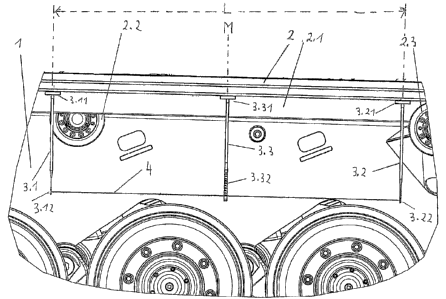
The only figure schematically illustrates a section from the


CA 02636530 2008-07-04

3
lateral area of e.g. a military tracked vehicle in which the chain
cover plates have been removed for showing the method and the
devices used. However, it is thereby pointed out that the method
may also be carried out with mounted chain cover plates, as shown
below.

The tracked vehicle 1 has a chain, a part of the upper strand 2 of
which is visible in the figure, which has guides 2.1 and runs over
track-supporting rollers 2.2 and 2.3.

The chain tension is to be measured over the longitudinal segment
L, the middle of which is designated with M.
Rod-shaped extension elements 3.1, 3.2 and 3.3 are fastened to the
upper strand 2 of the chain in vertical direction extending
downward. For fastening to the steel chain, the extension elements
have fastening plates 3.11, 3.21 and 3.31 formed as permanent
magnets on their upper ends in the drawing. The extension elements
3.1 and 3.2 are arranged respectively to the starting point and end
point of the predetermined longitudinal segment L. A cord 4 is
stretched between their lower ends 3.12 and 3.22 as a comparative
element in such a way that it extends in horizontal direction. To
this end, the ends 3.12 and 3.22 can, for example, each be provided
with an eye through which the cord 4 is drawn, whereby the two free
ends can be weighted with weights (not shown) . However, it can
also be fastened in another manner. The third extension element
3.3 situated in the middle M is provided with a measuring scale
3.32 in the area of its lower end.

It can be readily seen in the drawing that the slack of the upper
strand 2 of the chain on the longitudinal segment L can be measured
directly with aid of the extension element 3.3.

The starting point and the end point of the longitudinal segment L,


CA 02636530 2008-07-04

4
i.e. the measuring section, and the point of the greatest slack at
the middle M of this segment, more or less about the length of the
rods 3.1, 3.2 and 3.3, are placed downward by the arrangement of
the rod-shaped extension elements 3.1, 3.2 and 3.3. In particular
with a magnetic fastening, when the chain cover plates are mounted,
these extension elements can be inserted and fixed to the upper
strand 2 of the chain without great effort, so that the measuring
of the slack can be carried out in the lower area which is clearly
visible and accessible.

Dessin représentatif
Une figure unique qui représente un dessin illustrant l'invention.
États administratifs

Pour une meilleure compréhension de l'état de la demande ou brevet qui figure sur cette page, la rubrique Mise en garde , et les descriptions de Brevet , États administratifs , Taxes périodiques et Historique des paiements devraient être consultées.

États administratifs

Titre Date
Date de délivrance prévu 2011-09-20
(86) Date de dépôt PCT 2007-10-20
(87) Date de publication PCT 2008-05-02
(85) Entrée nationale 2008-07-04
Requête d'examen 2009-08-07
(45) Délivré 2011-09-20
Réputé périmé 2020-10-20

Historique d'abandonnement

Il n'y a pas d'historique d'abandonnement

Historique des paiements

Type de taxes Anniversaire Échéance Montant payé Date payée
Le dépôt d'une demande de brevet 400,00 $ 2008-07-04
Requête d'examen 800,00 $ 2009-08-07
Taxe de maintien en état - Demande - nouvelle loi 2 2009-10-20 100,00 $ 2009-09-23
Taxe de maintien en état - Demande - nouvelle loi 3 2010-10-20 100,00 $ 2010-09-24
Taxe finale 300,00 $ 2011-07-12
Taxe de maintien en état - brevet - nouvelle loi 4 2011-10-20 100,00 $ 2011-09-23
Taxe de maintien en état - brevet - nouvelle loi 5 2012-10-22 200,00 $ 2012-10-09
Taxe de maintien en état - brevet - nouvelle loi 6 2013-10-21 200,00 $ 2013-10-07
Taxe de maintien en état - brevet - nouvelle loi 7 2014-10-20 200,00 $ 2014-10-07
Taxe de maintien en état - brevet - nouvelle loi 8 2015-10-20 200,00 $ 2015-10-09
Taxe de maintien en état - brevet - nouvelle loi 9 2016-10-20 200,00 $ 2016-10-06
Taxe de maintien en état - brevet - nouvelle loi 10 2017-10-20 250,00 $ 2017-10-10
Taxe de maintien en état - brevet - nouvelle loi 11 2018-10-22 250,00 $ 2018-10-10
Titulaires au dossier

Les titulaires actuels et antérieures au dossier sont affichés en ordre alphabétique.

Titulaires actuels au dossier
KRAUSS-MAFFEI WEGMANN GMBH & CO. KG
Titulaires antérieures au dossier
WITTMANN, CHRISTOPH
Les propriétaires antérieurs qui ne figurent pas dans la liste des « Propriétaires au dossier » apparaîtront dans d'autres documents au dossier.
Documents

Pour visionner les fichiers sélectionnés, entrer le code reCAPTCHA :


Pour visualiser une image, cliquer sur un lien dans la colonne description du document. Pour télécharger l'image (les images), cliquer l'une ou plusieurs cases à cocher dans la première colonne et ensuite cliquer sur le bouton "Télécharger sélection en format PDF (archive Zip)" ou le bouton "Télécharger sélection (en un fichier PDF fusionné)".

Liste des documents de brevet publiés et non publiés sur la BDBC .

Si vous avez des difficultés à accéder au contenu, veuillez communiquer avec le Centre de services à la clientèle au 1-866-997-1936, ou envoyer un courriel au Centre de service à la clientèle de l'OPIC.


Description du
Document 
Date
(yyyy-mm-dd) 
Nombre de pages   Taille de l'image (Ko) 
Abrégé 2008-07-04 1 29
Revendications 2008-07-04 3 82
Dessins 2008-07-04 1 41
Description 2008-07-04 4 142
Dessins représentatifs 2008-07-04 1 47
Page couverture 2008-10-29 1 64
Dessins représentatifs 2011-08-24 1 33
Page couverture 2011-08-24 2 82
Revendications 2011-04-12 2 79
Description 2011-04-12 5 171
Abrégé 2011-05-16 1 29
PCT 2008-07-04 4 171
Cession 2008-07-04 2 94
Correspondance 2008-08-29 3 86
Poursuite-Amendment 2009-08-07 1 45
Poursuite-Amendment 2011-01-14 2 70
Poursuite-Amendment 2011-04-12 8 318
Correspondance 2011-07-12 2 62