Note : Les descriptions sont présentées dans la langue officielle dans laquelle elles ont été soumises.
CA 02637376 2008-07-16
Fuel/electric drive system
DESCRIPTION
Technical field
The invention relates to the field of drive systems. It
is based on a fuel/electric drive system as claimed in
the preamble of the independent claim.
Prior art
Nowadays fuel/electric drive systems are being
increasingly used in marine applications as well as
rail-bound vehicles and in automobiles. Such a
fuel/electric drive system according to the prior art
is shown by way of example in figure 1. In said figure,
the contemporary fuel/electric drive system has an
internal combustion engine and a generator which is
driven by the internal combustion engine. A
transmission is typically connected between the
internal combustion engine and the generator. The
generator typically has a single stator winding set. A
rectifier is connected on the alternating voltage side
to this stator winding set. The rectifier is also
CA 02637376 2008-07-16
- 2 -
connected on the direct voltage side to a direct
voltage circuit, with a power inverter for feeding a
drive motor being connected to the direct voltage
circuit.
The problem with a conventional fuel/electric drive
system described above, in particular the fuel/electric
drive system according to figure 1, is that when the
generator fails, for example due to a fault or short
circuit in one of the stator winding sets, the drive
motor can no longer be fed sufficiently and the entire
drive system is therefore no longer available. In
addition, the downstream elements, such as the
rectifier, direct voltage circuit, power inverter and
drive-motor, can be damaged when the generator fails.
Summary of the invention
The object of the invention is therefore to make
available a robust fuel/electric drive system which
also has a high level of availability. This object is
achieved via the features of claim 1. Advantageous
developments of the invention are given in the
dependent claims.
The fuel/electric drive system according to the
invention comprises an internal combustion engine and a
generator which is driven by the internal combustion
engine and which has a first stator winding set.
Furthermore, the fuel/electric drive system comprises a
first rectifier which is connected on the alternating
voltage side to the first stator winding set and on the
direct voltage side to a first direct voltage circuit.
In addition, the fuel/electric drive system comprises a
first power inverter which is connected on the direct
voltage side to the first direct voltage circuit and on
the alternating voltage side to a drive motor.
According to the invention, the generator has a second
CA 02637376 2008-07-16
3 -
stator winding set. Furthermore, a second rectifier is
connected on the alternating voltage side to the second
stator winding set and on the direct voltage side to a
second direct voltage circuit. Furthermore, a second
power inverter is connected on the direct voltage side
to the second direct voltage circuit and on the
alternating voltage side to the drive motor. Via the
second stator winding set, the second rectifier which
is connected to it and the power inverter which is
connected to the second rectifier via the second direct
voltage circuit, a redundant feed path for feeding the
drive motor is advantageously provided so that, for
example, in the event of a fault or short circuit in
one of the two stator winding sets, the drive motor can
advantageously be fed via the other feed path which is
not subject to a fault. The drive system therefore
continues to be available in the event of a fault.
Accordingly, the fuel/electric drive system according
to the invention is overall very robust. Furthermore,
the internal combustion engine can be operated with a
variable rotational speed and therefore advantageously
in a way which_is efficient in terms of fuel by means
of the generator with the two stator winding sets and
the downstream elements of the drive system. In
addition, by virtue of the operation with a variable
rotational speed, it is possible to dispense with a
transmission between the internal combustion engine and
generator.
This object and further objects, advantages and
features of the present invention are clear from the
following detailed description of preferred embodiments
of the invention in conjunction with the drawing.
Brief description of the drawings
In the drawings:
CA 02637376 2008-07-16
- 4 -
fig. 1 shows an embodiment of a fuel/electric drive
system according to the prior art,
fig. 2 shows a first embodiment of the fuel/electric
drive system according to the invention,
fig. 3 shows a second embodiment of the fuel/electric
drive system according to the invention, -
fig. 4 shows a third embodiment of the fuel/electric
drive system according to the invention,
fig. 5 shows a fourth embodiment of the fuel/electric
drive system according to the invention, and
fig. 6 shows a fifth embodiment of the fuel/electric
drive system according to the invention.
The reference symbols used in the drawing and their
meaning are listed together in the list of reference
symbols. Basically; identical parts are provided with
identical reference symbols in the figures. The
described embodiments are examples of the subject
matter of the invention and do not have a restrictive
effect.
Ways of implementing the invention
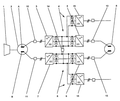
Fig. 2 shows a first embodiment of the fuel/electric
drive system according to the invention. In said
figure, the fuel/electric drive system comprises an
internal combustion engine 1 and a generator 2 which is
driven by the internal combustion engine 1 and which
has a first stator winding set A. The internal
combustion engine 1 is embodied, for example, as a
diesel engine, as a gas turbine or generally as any
internal combustion engine which is known to a person
skilled in the art. Furthermore, the fuel/electric
CA 02637376 2008-07-16
-
drive system comprises a first rectifier 3 which is
connected on the alternating voltage side to the first
stator winding set A and on the direct voltage side to
a first direct voltage circuit 4. In addition, the
5 fuel/electric drive system comprises a first power
inverter 5 which is connected on the direct *voltage
side to the first direct voltage circuit 4 and on the
alternating voltage side to a drive motor 6.
According to the invention, the generator 1 has a
second stator winding set A. Generally, each stator
winding set A, B comprises e phase windings, where
e? 3. In the embodiment in figure 2 and in the
embodiments according to figures 3 to 6 which are
described below in detail, in each case two stator
winding sets A, B with in each case e=3 phase windings
are assumed. Furthermore, according to figure 2, a
second rectifier 7 is connected on the alternating
voltage side to the second stator winding set B and on
the direct voltage side to a second direct voltage
circuit 8. Moreover, a second power inverter 9 is
connected on the direct voltage side to the second
direct voltage circuit 8 and on the alternating voltage
side to the drive motor 6. The drive motor 6 likewise
generally comprises two stator winding sets, each
stator winding set having a phase winding, where a?3.
In the embodiment in figure 2 and in the embodiments
according to figures 3 to 6 which are described below
in detail, in each case two stator winding sets with in
each case a=3 phase windings are assumed for the drive
motor 6. Using the second stator winding set B of the
generator 2, of the second rectifier 7 which is
connected to it and of the power inverter 9 which is
connected to the second rectifier 7 via the second
direct voltage circuit 8, a redundant feed path for
feeding the drive motor 6 is advantageously provided so
that, for example, in the event of a fault or short
circuit in one of the two stator winding sets A, B, the
drive motor 6 can advantageously be fed via the other
CA 02637376 2008-07-16
6 -
feed path which is not subject to a fault. As a result,
the fuel/electric drive system continues to be
available in the event of a fault, i.e. the drive motor
6 can continue to be fed. Accordingly, the
fuel/electric drive system according to the invention
is very robust overall and has a high level of
availability. Furthermore, the internal combustion
engine 1 can be operated with a variable rotational
speed and therefore advantageously in a way which is
efficient in terms of fuel by means of the generator 2
with the two stator winding sets A, B and the
downstream elements 3, 4, 5, 6 of the drive system. In
addition, by virtue of the operation with a variable
rotational speed it is possible to dispense with a
transmission 40 which is customarily connected between
the interrial combustion engine 1 and the generator 2,
as is shown in the embodiment of the fuel/electric
drive system according to the prior art.
According to fig. 2, an isolating switch 10 is
connected into the connection of the first stator
winding set A to the first rectifier 3, and an
isolating switch 11 is connected into the connection of
the second stator winding set B to the second rectifier
7. If, for example, a fault occurs in one of the stator
winding sets A, B of the generator 2, the rectifier 3,
7 which is connected to the stator winding set A, B
which is subject to a fault can be disconnected easily
and quickly by means of the respective isolating switch
10, 11, and this rectifier 3, 7 and the downstream
elements such as the direct voltage circuit 4, 8, power
inverter 5, 9 and drive motor 6 can be protected
against damage or even destruction. Of course, the
respective isolating switch 10, 11 also permits the
respective stator winding set A, B of the generator 2
to be disconnected in the event of a fault on the part
of the respective rectifier 3, 7. The respective
isolating switch 10, 11 of course also permits the
corresponding stator winding set A, B to be reconnected
CA 02637376 2008-07-16
- 7 -
to the respective rectifier 3, 7, for example after the
fault which occurs has been checked or after
maintenance or repair work.
According to fig. 2, an isolating switch 12 is
connected into the connection of the first power
inverter 5 to the drive motor 6 and an isolating switch
13 is also connected irito the connection of the second
power inverter 9 to the drive motor 6. If, for example,
a fault occurs in the drive motor 6, the respective
power inverter 5, 9 which is connected to the drive
motor 6 can be disconnected easily and quickly by means
of the respective isolating switch 12, 13, and the
respective power inverter 5, 9 and the preceding
elements such as the direct voltage circuit 4, 8,
rectifier 3, 7 and generator 2 can be protected against
damage or even destruction. Of course, the respective
isolating switch 12, 13 also permits the drive motor 6
to be disconnected in the event of a fault on the part
of the respective power inverter 5, 9. The respective
isolating switch 12, 13 of course also permits the
drive motor 6 to be reconnected to the respective power
inverter 5, 9, for example after the fault which occurs
has been checked or after maintenance or repair work.
Furthermore, the first direct voltage circuit 4 can be
connected to the second direct voltage circuit 8 and
disconnected from it via a connecting switch 14. The
connecting switch 14 therefore makes it possible to
feed one of the direct voltage circuits 4, 8 by means
of the respective other direct voltage circuit 4, 8 if,
for example, the connection of the first stator winding
set A with the first rectifier 3 has been disconnected
by means of the isolating switch 10, or the connection
of the second stator winding set B to the second
rectifier 7 has been disconnected by means of the
isolating switch 11 owing to a fault as mentioned
above. Accordingly, in the event of a fault, the drive
motor 6 can also advantageously be fed from the first
CA 02637376 2008-07-16
- 8 -
direct voltage circuit 4 by means of the first power
inverter 5, and additionally also fed from the second
direct voltage circuit 8 by means of the second power
inverter 9.
In addition, x further power inverters 15 are generally
connected on the direct voltage side to the first
direct voltage circuit 4, where x _ 1, and in fig. 2
x=1 such further power inverters 15 are connected on
the direct voltage side to the first direct voltage
circuit 4. Each of the further x power inverters 15
makes it advantageously possible to feed, for example,
a further drive motor but also, for example, to feed
auxiliary operating devices such as fans, air-
conditioning systems, actuator motors etc. Of course,
such a power inverter 15 is also designed to be capable
of feeding back energy. In addition, generally y
further power inverters 16 are connected on the direct
voltage side to the second direct voltage circuit 8,
where y> 1, and in fig. 2 y=1 such further power
inverters 16 are connected on the direct voltage side
to the second direct voltage circuit 8. Each of the
further y power inverters 16 also advantageously makes
it possible in this case to feed, for example, a
further drive motor but also to feed, for example,
auxiliary operating devices such as fans, air-
conditioning systems, actuator motors etc.
Fig. 3 shows a.second embodiment of the fuel/electric
drive system according to the invention. On the basis
of fig. 2, the fuel/electric drive system according to
fig. 3 generally has z further power inverters 17 which
are connected on the direct voltage side to the first
direct voltage circuit 4 and to the second direct
voltage circuit 8, where z _ 1, and in fig. 3 z=1 such
further power inverters 17 are connected on the direct
voltage side to the first direct voltage circuit 4 and
to the second direct voltage circuit 8. As a result,
each of the further z power inverters 17 can
CA 02637376 2008-07-16
9 -
advaritageously be fed from both direct voltage circuits
4, 8, in which case each of the further z power
inverters 17 makes it possible to feed, for example, a
further drive motor but also to feed, for example,
auxiliary operating devices -such as fans, air-
conditioning systems, actuator motors etc. Of course,
such a power inverter 17 is also designed to be capable
of feeding back energy. According to fig. 3, an element
18 for limiting the direction of current is connected
into each connection of the first direct voltage
circuit 4 to one of the z further power inverters 17,
and an element 19 for limiting the direction of current
is connected into each connection of the second direct
voltage circuit 8 to one of the z further power
inverters 17. The respective element 18, 19 for
limiting the direction of current serves to ensure that
only a current in a defined direction of current flows
from the respective direct voltage circuit 4, 8 to the
respective power inverter 17 of the z further power
inverter 17 and back again in a defined fashion. This
advantageously avoids a situation in which a faulty
current, caused for example by faults in the respective
direct voltage circuits 4, 8 and/or by a fault in one
of the z further power inverters 17, can flow to the
respective power inverter 17 or into the respective
direct voltage circuit 4, 8 and damages or even
destroys the respective power inverter 17 or the
elements which are directly and indirectly connected to
the respective direct voltage circuit 4, 8. The
respective element 18, 19 for limiting the direction of
current is preferably embodied by means of diodes
according to fig. 3 and therefore can be implemented in
a way which is very simple and space-saving. However,
switching elements which can be actuated, in particular
power semiconductor switches which can be actuated, are
also conceivable. It is to be noted that the z further
power inverters 17 and their connections on the direct
voltage side which are described in detail above with
reference to fig. 3 can also be combined with the
CA 02637376 2008-07-16
- 10 -
fuel/electric drive system according to fig. 2 and with
the fuel/electric drive systems according to fig. 4,
fig. 5 and fig. 6 which are also described in detail
below.
Fig. 4 illustrates a third embodiment of the
fuel/electric drive system according to the invention.
On the basis of fig. 2, generally n further rectifiers
20 are connected on the alternating voltage side to the
first stator winding set A according to fig. 4, where
n? 1, and in fig. 4 n=1 further rectifiers 20 are
connected on the alternating voltage side to the first
stator winding set A. In addition, according to fig. 4
generally m further power inverters 21 are connected to
in each case one of the n rectifiers 20 via a direct
voltage circuit 22 which is provided for each of the n
further rectifiers 20, where m>_ 1, and in fig. 4 m=1
further power inverters 21 are connected to in each
case one of the n rectifiers 20 via a direct voltage
circuit 22 which is provided for each of the n further
rectifiers 20. The first stator winding set A can
therefore be used to feed, for example, not only a
further drive motor but, for example, also auxiliary
operating devices such as fans, air-conditioning
systems, actuator motors etc. by means of the
respective further power inverter 21 of the m further
power inverters 21 separately from and independently of
the first and second direct voltage circuit 4, 8.
Furthermore, according to fig. 4, p further rectifiers
26 are connected on the alternating voltage side to the
second stator winding set B, where p _ 1, and in fig. 4
p=1 further rectifiers 26 are connected on the
alternating voltage side to the second stator winding
set B. In addition, according to.fig. 4 generally q
further power inverters 27 are connected in each case
to one of the p rectifiers 26 via a direct voltage
circuit 28 which is provided for each of the p further
rectifiers 26, where q _ 1, and in fig. 4 q=1 further
power inverters 27 are connected to in each case one of
CA 02637376 2008-07-16
- 11 -
the p rectifiers 26 via a direct voltage circuit 28
which is provided for each of the p further rectifiers
26. The second stator winding set B can therefore be
used to feed, for example, not only a further drive
motor but, for example, also auxiliary operating
devices such as fans, air-conditioning systems,
actuator motors etc. by means of the respective further
power inverter 27 of the q further power inverters 27
separately from and independently of the first and
second direct voltage circuits 4, 8. According to
fig. 4, an isolating switch 25 is connected into each
connection of the first stator winding set A to one of
the n further rectifiers 20. Furthermore, according to
fig. 4, an isolating switch 31 is additionally
connected into each connection of the second stator
winding set B to one of the p further rectifiers 26.
If, for example, a fault occurs in one of the stator
winding sets A, B of the generator 2, the further
rectifier 20, 26 which is connected to the stator
winding set A. B which is subject to a fault can be
disconnected easily and quickly by means of the
respective isolating switch 25, 31, and this further
rectifier 20, 26 and the downstream elements such as
the direct voltage circuit '22, 28 and further power
inverters 21, 27 can be protected against damage or
even destruction. Of course, the respective isolating
switch 25, 31 also permits the respective stator
winding set A, B of the generator 2 to be disconnected
in the event of a fault on the part of the respective
further rectifier 20, 26. Of course, the respective
isolating switch 25, 31 also permits the corresponding
stator winding set A, B to be reconnected to the
respective further rectifier 20, 26, for example after
the fault which occurs has been checked or after
maintenance or repair work. It is to be noted that the
n further rectifiers 20 and their connections which are
described above in detail with respect to fig. 4 and
the p further rectifiers 26 and their connections which
are described above in detail with respect to fig. 4
CA 02637376 2008-07-16
- 12 -
can also be combined with the fuel/electric drive
system according to fig. 2, fig. 3 and with the
fuel/electric drive systems according to fig. 5 and
fig. 6 which are also described in detail below.
Fig. 5 shows a fourth embodiment of the fuel/electric
drive system according to the invention. On the basis
of fig. 4, n further rectifiers 20 are connected on the
alternating voltage side to the first stator winding
set A according to fig. 5, in a way which generally
corresponds to fig. 4, where n> 1, and in fig. 5 n=1
further rectifiers 20 are connected on the alternating
voltage side to the first stator winding set A. In
addition, according to fig. 5 generally m further power
inverters 21 are connected to in each case one of the n
rectifiers 20 via a direct voltage circuit 22 which is
provided for each of the n further rectifiers 20, where
m> 1, and in fig. 5 m=1 further power inverters 21 are
connected to in each case one of the n rectifiers 20
via a direct voltage circuit 22 which is provided for
each of the n further rectifiers 20. The first stator
winding set A can therefore be used to feed, for
example, not only a further drive motor but, for
example, also auxiliary operating devices such as fans,
air-conditioning systems, actuator motors etc.
separately from and independently of the first and
second direct voltage circuits 4, 8 by means of the
respective further power inverter 21 of the m further
power inverters 21. According to fig. 5, an isolating
switch 25 is connected into each connection of the
first stator winding set A to one of the n further
rectifiers 20, in which context the statements relating
to fig. 4 should be referred to with regard to the
method of functioning and advantages. Furthermore,
according to fig. 5 generally r further rectifiers 23
are connected on the alternating voltage side to the
second stator winding set B, where r>_ 1 and n _ r, and
in fig. 5 r=1 further rectifiers 23 are connected on
the alternating voltage side to the second stator
CA 02637376 2008-07-16
- 13 -
winding set B. In addition, according to fig. 5, each
of the r further rectifiers 23 is connected on the
direct voltage side to in each case one of the direct
voltage circuits 22 which are provided for the n
further rectifiers 20. In the event of a fault, for
example in the first stator winding set A of the
generator 2, the respective further rectifier 20 is
disconnected by means of the isolating switch 25, in
which case the direct voltage circuit 22 which is
connected to the further disconnected rectifier 20 can
advantageously be fed by means of the further rectifier
23 thereby making it possible to feed not only a
further drive motor but, for example, also auxiliary
operating devices such as fans, air-conditioning
systems, actuator motors etc. from this direct voltage
circuit 22 by means of the further power inverter 21,
even in such a case of a fault. In addition, an
isolating switch 24, which advantageously permits the
further respective rectifier 23 to be disconnected and
reconnected to the second stator winding set B of the
generator 2, is connected into each connection of the
second stator winding set B to one of the r further
rectifiers 23. It is to be noted that the r further
rectifiers 23 and their connections which are described
in detail above with reference to fig. 5 can also be
combined with the fuel/electric drive system according
to fig. 2, fig. 3 and fig. 4 as well as with the
fuel/electric drive system according to fig. 6 which is
described in detail below.
Fig. 6 shows a fifth embodiment of the fuel/electric
drive system according to the invention. On the basis
of fig. 4, p further rectifiers 26 are connected on the
alternating voltage side to the second stator winding
set B according to fig. 6 in a way which generally
corresponds to fig. 4, where p _ 1, and in fig. 6 p=l
further rectifiers 26 are connected on the alternating
voltage side to the second stator winding set B. In
addition, according to fig. 6, q further power
CA 02637376 2008-07-16
- 14 -
inverters 27 are generally connected in each case to
one of the p rectifiers 26 via a direct voltage circuit
28 which is provided for each of the p further
rectifiers 26, where q? 1, and in fig. 6 q=1 further
power inverters 27 are connected to in each case one of
the p rectifiers 26 via a direct voltage circuit 28
which is provided for each of the p further rectifiers
26. The second stator winding set B can therefore be
used to feed, for example, not only a further drive
motor but, for example, also auxiliary operating
devices such as fans, air-conditioning systems,
actuator motors etc. separately from and independently
of the first and second direct voltage circuits 4, 8 by
means of the respective further power inverter 27 of
the q further power inverters 27. According to fig. 6,
an isolating switch 31 is connected into each
connection of the second stator winding set B to one of
the p further rectifiers 26, and in this context the
statements relating to fig. 4 should be referred to
with regard to the method of functioning and
advantages. Furthermore, according to fig. 6 generally
v further rectifiers 29 are connected on the
alternating voltage side to the first stator winding
set A, where v _ 1 and p _ v, and in fig. 6 v=1 further
rectifiers 29 are connected on the alternating voltage
side to the first stator winding set A. In addition,
according to fig. 6 each of the v further rectifiers 29
is connected on,the direct voltage side to in each case
one of the direct voltage circuits 28 which are
provided for the p further rectifiers 26. In the event
of a fault in, for example, the second stator winding
set B of the generator 2, the respective further
rectifier 26 is disconnected by means of the isolating
switch 31, in which case the direct voltage circuit 28
which is connected to the further disconnected
rectifier 26 can advantageously be fed by means of the
further rectifier 29, therefore making it possible to
feed a further drive motor and, for example, also to
feed auxiliary operating devices such as fans, air-
CA 02637376 2008-07-16
- 15 -
conditioning systems, actuator ntotors etc. from this
direct voltage circuit 28 by means of the further power
inverter 27, even in such a case of a fault. In
addition, an isolating switch 30, which advantageously
permits the respective further rectifier 29 to be
disconnected and reconnected to the first stator
winding set A of the generator 2, is connected into
each connection of the first stator winding set A to
one of the v further rectifiers 29. It is to be noted
that the v further rectifiers 29 and their connections
which are described in detail above with reference to
fig. 6 can also be combined with the fue-l/electric
drive system according to fig. 2, fig. 3, fig. 4 and
fig. 5.
CA 02637376 2008-07-16
- 16 -
List of reference symbols
1 Internal combustion engine
2 Generator
3 First rectifier
4 First direct voltage circuit
First power inverter
6 Drive motor
7 Second rectifier
8 Second direct voltage circuit
9 Second power inverter
10, 11, 12 isolating switch
13, 24, 25
30, 31
14 Connecting switch
x further power inverters, where x1
16 y further power inverters, where y1
17 z further power inverters, where z1
18, 19 Element for limiting the direction of
current
n further rectifiers, where n _ 1
21 m further power inverters, where m? 1
22 Direct voltage circuit of each of the n
further rectifiers 20
23 r further rectifiers, where r1
26 p further rectifiers, where p1
27 q further power inverters, where q>_ 1
28 Direct voltage circuit of each of the p
further rectifiers 26
29 v further rectifiers, where v _ 1
40 Transmission
A, B Stator winding sets of the generator