Sélection de la langue

Search

Sommaire du brevet 2638336 

Énoncé de désistement de responsabilité concernant l'information provenant de tiers

Une partie des informations de ce site Web a été fournie par des sources externes. Le gouvernement du Canada n'assume aucune responsabilité concernant la précision, l'actualité ou la fiabilité des informations fournies par les sources externes. Les utilisateurs qui désirent employer cette information devraient consulter directement la source des informations. Le contenu fourni par les sources externes n'est pas assujetti aux exigences sur les langues officielles, la protection des renseignements personnels et l'accessibilité.

Disponibilité de l'Abrégé et des Revendications

L'apparition de différences dans le texte et l'image des Revendications et de l'Abrégé dépend du moment auquel le document est publié. Les textes des Revendications et de l'Abrégé sont affichés :

  • lorsque la demande peut être examinée par le public;
  • lorsque le brevet est émis (délivrance).
(12) Brevet: (11) CA 2638336
(54) Titre français: DISPOSITIF DE CONTROLE DE PRESSION D'UNE INSTALLATION DE PLOMBERIE
(54) Titre anglais: APPARATUS FOR PRESSURE TESTING A PLUMBING INSTALLATION
Statut: Octroyé
Données bibliographiques
(51) Classification internationale des brevets (CIB):
  • G01M 3/28 (2006.01)
  • F16K 7/12 (2006.01)
  • F16L 55/00 (2006.01)
  • F16L 55/11 (2006.01)
  • F16L 55/128 (2006.01)
  • E03C 1/00 (2006.01)
  • E03F 7/02 (2006.01)
(72) Inventeurs :
  • COSCARELLA, GABE (Canada)
(73) Titulaires :
  • COSCARELLA, GABE (Canada)
(71) Demandeurs :
  • COSCARELLA, GABE (Canada)
(74) Agent: WOODRUFF, NATHAN V.
(74) Co-agent:
(45) Délivré: 2015-10-06
(22) Date de dépôt: 2008-07-21
(41) Mise à la disponibilité du public: 2010-01-21
Requête d'examen: 2013-06-25
Licence disponible: S.O.
(25) Langue des documents déposés: Anglais

Traité de coopération en matière de brevets (PCT): Non

(30) Données de priorité de la demande: S.O.

Abrégés

Abrégé français

Appareil dessai de pression dune installation de plomberie comprenant un corps cylindrique souple doté dune paroi latérale périphérique, dune extrémité fermée et dune extrémité ouverte. Une bride de positionnement sallonge vers lextérieur à partir de la paroi latérale périphérique, à lextrémité ouverte, pour faciliter le positionnement du corps cylindrique par rapport à une extrémité dun tuyau dans lequel le corps cylindrique a été inséré. Une paroi dextrémité est positionnée sur lextrémité fermée. La paroi dextrémité est incurvée vers lintérieur et comporte un canal découlement cylindrique interne refermé par un bouchon partiellement amovible. Une bande de préhension est fixée au bouchon partiellement amovible qui ferme une prise cylindrique interne et qui, de plus, traverse lextrémité ouverte du corps. Ainsi, lorsquune force est exercée sur la bande de préhension, le bouchon se soulève pour ouvrir le canal découlement cylindrique et, lorsquune force continue dêtre exercée sur la bande de préhension, le corps cylindrique roule vers lintérieur, permettant ainsi au corps cylindrique dêtre retiré du tuyau.


Abrégé anglais

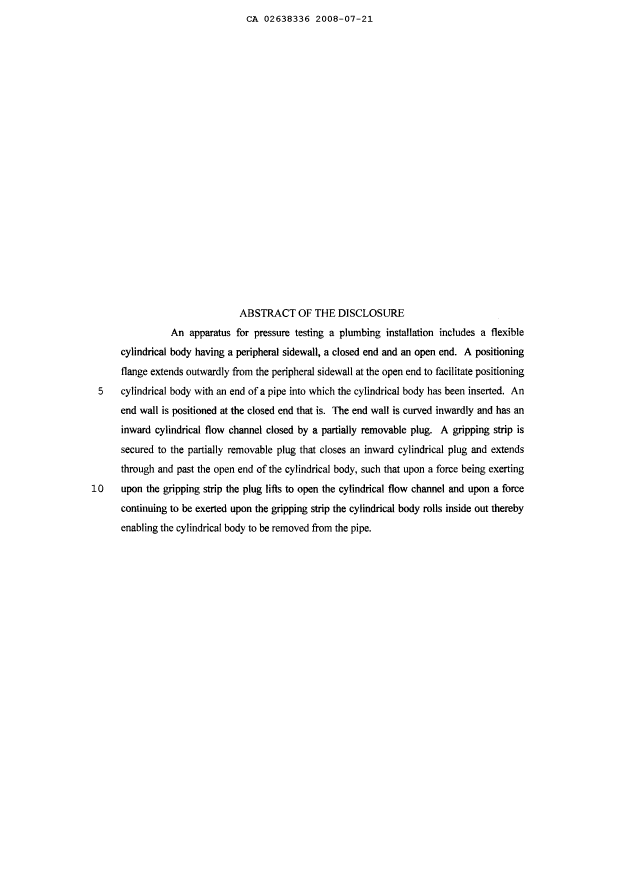
An apparatus for pressure testing a plumbing installation includes a flexible cylindrical body having a peripheral sidewall, a closed end and an open end. A positioning flange extends outwardly from the peripheral sidewall at the open end to facilitate positioning cylindrical body with an end of a pipe into which the cylindrical body has been inserted. An end wall is positioned at the closed end that is. The end wall is curved inwardly and has an inward cylindrical flow channel closed by a partially removable plug. A gripping strip is secured to the partially removable plug that closes an inward cylindrical plug and extends through and past the open end of the cylindrical body, such that upon a force being exerting upon the gripping strip the plug lifts to open the cylindrical flow channel and upon a force continuing to be exerted upon the gripping strip the cylindrical body rolls inside out thereby enabling the cylindrical body to be removed from the pipe.

Revendications

Note : Les revendications sont présentées dans la langue officielle dans laquelle elles ont été soumises.


5
What is Claimed is:
1. An apparatus for pressure testing a plumbing installation, comprising:
a flexible cylindrical body having a peripheral cylindrical sidewall, a closed
end, and
an open end;
a positioning flange extending outwardly from the peripheral cylindrical
sidewall at
the open end to facilitate positioning the cylindrical body within an end of a
pipe of the
plumbing installation into which the cylindrical body has been inserted, the
peripheral
cylindrical sidewall engaging an inner surface of the pipe;
an end wall at the closed end, the end wall being curved inwardly where the
end wall
connects to the peripheral cylindrical sidewall and having an inward
cylindrical flow channel
closed by a partially removable plug; and
a gripping strip secured to the partially removable plug and extending through
and
past the open end of the cylindrical body, such that upon a force being
exerted upon the
gripping strip, the partially removable plug lifts to open the cylindrical
flow channel and upon
the force continuing to be exerted upon the gripping strip, the cylindrical
body rolls inside out
thereby enabling the cylindrical body to be removed from the pipe.
2. The apparatus of claim 1, wherein the peripheral cylindrical sidewall is
friction fit into the
pipe.
3. A method of pressure testing a plumbing installation, comprising the steps
of:
providing:
a flexible cylindrical body having a peripheral cylindrical sidewall, a closed

end, and an open end;
a positioning flange extending outwardly from the peripheral cylindrical
sidewall at the open end;
an end wall at the closed end, the end wall being curved inwardly where the
end wall connects to the peripheral cylindrical sidewall and having an inward
cylindrical flow
channel closed by a partially removable plug; and
a gripping strip secured to the partially removable plug and extending through

6
and past the open end of the cylindrical body;
insetting the flexible cylindrical body into a pipe of the plumbing
installation such that
the peripheral cylindrical sidewall seals and is friction fit against an inner
surface of the pipe;
installing a fitting such that the positioning flange is secured between the
fitting and
an end of the pipe;
performing a pressure test by pressurizing the pipe; and
removing the flexible cylindrical body from the tubular body by exerting a
force upon
the partially removable plug via the gripping strip to open the cylindrical
flow channel and
continuing to exert a force upon the gripping strip to roll the cylindrical
body inside out.

Description

Note : Les descriptions sont présentées dans la langue officielle dans laquelle elles ont été soumises.


CA 02638336 2008-07-21
1
TITLE
[0001] Apparatus for pressure testing a plumbing installation
FIELD
[0002] Pressure testing of plumbing installations to check for leaks.
BACKGROUND
[0003] United States Patent 6,082,183 (Huber) discloses a dome shaped baffle
structure
that is held in position within a pipe by an annular baffle carriage. A line
is attached to a lug
positioned on a concave surface of the dome shaped baffle. Upon a force being
exerted upon a
lug, the dome shaped baffle collapses and is released from the baffle
carriage.

SUMMARY
[0004] There is provided an apparatus for pressure testing a plumbing
installation,
comprising a flexible cylindrical body having a peripheral sidewall, a closed
end and an open
end. A positioning flange extends outwardly from the peripheral sidewall at
the open end to
facilitate positioning the cylindrical body within an end of a pipe into which
the cylindrical
body has been inserted. An end wall is positioned at the closed end. The end
wall is curved
inwardly where the end wall connects to the peripheral sidewall and having an
inward
cylindrical flow channel closed by a partially removable plug. A gripping
strip is secured to
the partially removable plug and extends through and past the open end of the
cylindrical
body, such that upon a force being exerting upon the gripping strip the
partially removable
plug lifts to open the cylindrical flow channel and upon a force continuing to
be exerted upon
the gripping strip the cylindrical body rolls inside out thereby enabling the
cylindrical body to
be removed from the pipe.

BRIEF DESCRIPTION OF THE DRAWINGS
[0005] These and other features will become more apparent from the following
description in which reference is made to the appended drawings, the drawings
are for the
purpose of illustration only and are not intended to be in any way limiting,
wherein:
FIG. 1 is a side view in section of an apparatus for pressure testing a
plumbing
installation.


CA 02638336 2008-07-21
2

FIG. 2 is a side view in section of an alternative design for the apparatus
shown in
FIG. 1.
FIG. 3 is a side view in section of the apparatus of FIG. 2 with the partially
removable plug opened.
FIG. 4 is a side view in section of the apparatus of FIG. 2 with a plug
inserted
into the cylindrical flow channel.
FIG. 5 is a side view in section of the apparatus of FIG. 2 with the
cylindrical
body being rolled out of a pipe.
FIG. 6 through 8 are side views in section of alternative designs for the
apparatus
shown in FIG. 1.

DETAILED DESCRIPTION
[0006] An apparatus for pressure testing a plumbing installation, generally
identified by
reference numeral 10, will now be described with reference to FIG. 1 through
5.
Structure and Relationship of Parts:
[0007] Referring to FIG. 1, apparatus 10 includes a flexible cylindrical body
12 having a
peripheral sidewall 14, a closed end 16 and an open end 18. A positioning
flange 20 extends
outwardly from peripheral sidewall 14 at open end 18 to facilitate positioning
cylindrical
body 12 within an end of a pipe 21 into which cylindrical body 12 has been
inserted. When
inserted into pipe 21, sidewall 14 creates a seal between cylindrical body 12
and pipe 21. An
end wall 22 is positioned at closed end 16. End wal122 is curved inwardly
where end wall 22
connects to peripheral sidewall 14, and has an inward cylindrical flow channel
24 closed by a
partially removable plug 26. Plug 26 may be frangible, attached by adhesive,
or may be an
insert. A gripping strip 28 is secured to plug 26 and extends through and past
open end 18 of
cylindrical body 12, such that when a certain force is exerted upon gripping
strip 28, the plug
lifts to open cylindrical flow channe124. Upon a force continuing to be
exerted upon gripping
strip 28, cylindrical body 12 rolls inside out thereby enabling cylindrical
body 12 to be
removed from pipe 21. A plug 30 is provided to re-seal cylindrical flow
channel 24 if it
becomes necessary to perform another pressure test.

Operation:


CA 02638336 2008-07-21
3

[0008] The use of apparatus 10 will now be described with respect to the
embodiment
shown in FIG. 2 through 5. Referring to FIG. 1, cylindrical body 12 is first
inserted into pipe
21. Cylindrical body 12 is designed to be friction fit into pipe 21, and
flange 20 provides an
additional stop surface that is butted up against a shoulder in fitting 32. As
the plumbing
system, of which pipe 21 and fitting 32 form part of, is pressure tested, the
pressure builds
against curved end wall. The curved surface converts the axial pressure into
radial pressure
which provides and additional sealing pressure to cylindrical body 12.
Referring to FIG. 3,
once the pressure test is complete, gripping strip 28 is pulled to open plug
26 to allow the
fluid to escape through cylindrical flow channel 24. Referring to FIG. 4, if
it is necessary to
retest the plumbing installation, plug 30 can be used to block cylindrical
flow channel 24 to
allow the testing to reoccur. Referring to FIG. 5, once the pressure testing
is completed,
gripping strip 28 is pulled further to cause cylindrical body 12 to "roll" out
of pipe 21, such
that it can be removed. By applying a force at this point, sidewall 14 is
collapsed inward,
such that it pulls away from pipe 21.
Variations:
[0009] Referring to FIG. 6 through 8, additional designs of end wall 22 are
shown. As
can be seen from a comparison of the various embodiments depicted herein, it
is important
that end wal122 meet peripheral sidewall 14 in a manner that allows body 12 to
roll out.

[0010] In this patent document, the word "comprising" is used in its non-
limiting sense to
mean that items following the word are included, but items not specifically
mentioned are not
excluded. A reference to an element by the indefinite article "a" does not
exclude the
possibility that more than one of the element is present, unless the context
clearly requires that
there be one and only one of the elements.

[0011] The following claims are to be understood to include what is
specifically
illustrated and described above, what is conceptually equivalent, and what can
be obviously
substituted. Those skilled in the art will appreciate that various adaptations
and modifications
of the described embodiments can be configured without departing from the
scope of the
claims. The illustrated embodiments have been set forth only as examples and
should not be
taken as limiting the invention. It is to be understood that, within the scope
of the following


CA 02638336 2008-07-21
4

claims, the invention may be practiced other than as specifically illustrated
and described.

Dessin représentatif
Une figure unique qui représente un dessin illustrant l'invention.
États administratifs

Pour une meilleure compréhension de l'état de la demande ou brevet qui figure sur cette page, la rubrique Mise en garde , et les descriptions de Brevet , États administratifs , Taxes périodiques et Historique des paiements devraient être consultées.

États administratifs

Titre Date
Date de délivrance prévu 2015-10-06
(22) Dépôt 2008-07-21
(41) Mise à la disponibilité du public 2010-01-21
Requête d'examen 2013-06-25
(45) Délivré 2015-10-06

Historique d'abandonnement

Il n'y a pas d'historique d'abandonnement

Taxes périodiques

Dernier paiement au montant de 236,83 $ a été reçu le 2023-07-12


 Montants des taxes pour le maintien en état à venir

Description Date Montant
Prochain paiement si taxe générale 2024-07-22 624,00 $
Prochain paiement si taxe applicable aux petites entités 2024-07-22 253,00 $

Avis : Si le paiement en totalité n'a pas été reçu au plus tard à la date indiquée, une taxe supplémentaire peut être imposée, soit une des taxes suivantes :

  • taxe de rétablissement ;
  • taxe pour paiement en souffrance ; ou
  • taxe additionnelle pour le renversement d'une péremption réputée.

Les taxes sur les brevets sont ajustées au 1er janvier de chaque année. Les montants ci-dessus sont les montants actuels s'ils sont reçus au plus tard le 31 décembre de l'année en cours.
Veuillez vous référer à la page web des taxes sur les brevets de l'OPIC pour voir tous les montants actuels des taxes.

Historique des paiements

Type de taxes Anniversaire Échéance Montant payé Date payée
Le dépôt d'une demande de brevet 200,00 $ 2008-07-21
Taxe de maintien en état - Demande - nouvelle loi 2 2010-07-21 50,00 $ 2010-04-23
Taxe de maintien en état - Demande - nouvelle loi 3 2011-07-21 50,00 $ 2011-06-22
Taxe de maintien en état - Demande - nouvelle loi 4 2012-07-23 50,00 $ 2012-06-21
Requête d'examen 400,00 $ 2013-06-25
Taxe de maintien en état - Demande - nouvelle loi 5 2013-07-22 100,00 $ 2013-06-25
Taxe de maintien en état - Demande - nouvelle loi 6 2014-07-21 100,00 $ 2014-06-24
Taxe de maintien en état - Demande - nouvelle loi 7 2015-07-21 100,00 $ 2015-05-13
Taxe finale 150,00 $ 2015-06-10
Taxe de maintien en état - brevet - nouvelle loi 8 2016-07-21 100,00 $ 2016-06-24
Taxe de maintien en état - brevet - nouvelle loi 9 2017-07-21 100,00 $ 2017-07-05
Taxe de maintien en état - brevet - nouvelle loi 10 2018-07-23 125,00 $ 2018-07-04
Taxe de maintien en état - brevet - nouvelle loi 11 2019-07-22 125,00 $ 2019-07-08
Taxe de maintien en état - brevet - nouvelle loi 12 2020-07-21 125,00 $ 2020-07-20
Taxe de maintien en état - brevet - nouvelle loi 13 2021-07-21 125,00 $ 2021-07-21
Taxe de maintien en état - brevet - nouvelle loi 14 2022-07-21 125,00 $ 2022-07-21
Taxe de maintien en état - brevet - nouvelle loi 15 2023-07-21 236,83 $ 2023-07-12
Titulaires au dossier

Les titulaires actuels et antérieures au dossier sont affichés en ordre alphabétique.

Titulaires actuels au dossier
COSCARELLA, GABE
Titulaires antérieures au dossier
S.O.
Les propriétaires antérieurs qui ne figurent pas dans la liste des « Propriétaires au dossier » apparaîtront dans d'autres documents au dossier.
Documents

Pour visionner les fichiers sélectionnés, entrer le code reCAPTCHA :


Pour visualiser une image, cliquer sur un lien dans la colonne description du document. Pour télécharger l'image (les images), cliquer l'une ou plusieurs cases à cocher dans la première colonne et ensuite cliquer sur le bouton "Télécharger sélection en format PDF (archive Zip)" ou le bouton "Télécharger sélection (en un fichier PDF fusionné)".

Liste des documents de brevet publiés et non publiés sur la BDBC .

Si vous avez des difficultés à accéder au contenu, veuillez communiquer avec le Centre de services à la clientèle au 1-866-997-1936, ou envoyer un courriel au Centre de service à la clientèle de l'OPIC.


Description du
Document 
Date
(yyyy-mm-dd) 
Nombre de pages   Taille de l'image (Ko) 
Abrégé 2008-07-21 1 22
Description 2008-07-21 4 135
Revendications 2008-07-21 1 22
Dessins 2008-07-21 4 55
Dessins représentatifs 2009-12-31 1 7
Page couverture 2010-01-13 1 43
Revendications 2014-10-21 2 54
Dessins représentatifs 2015-09-08 6 84
Page couverture 2015-09-08 1 43
Revendications 2014-11-14 2 55
Correspondance 2008-09-24 1 59
Cession 2008-07-21 2 84
Correspondance 2010-03-23 1 39
Taxes 2010-04-23 1 28
Correspondance 2011-03-31 3 155
Correspondance 2011-05-16 1 20
Correspondance 2011-05-16 1 35
Poursuite-Amendment 2014-04-24 4 159
Poursuite-Amendment 2013-06-25 1 34
Poursuite-Amendment 2014-10-21 7 192
Poursuite-Amendment 2014-11-14 5 112
Correspondance 2015-06-10 1 32