Note : Les descriptions sont présentées dans la langue officielle dans laquelle elles ont été soumises.
CA 02638435 2008-07-31
DIRECT-FIRED DUCTABLE HEATER
FIELD OF THE INVENTION
The invention relates to heaters typically used in temporary applications and
more specifically to direct-fired ductable heaters.
BACKGROUND
Heaters are typically used in temporary applications, such as construction
sites,
as a temporary heat source before a primary and permanent heat source is
functional and usable or for example for heating event tents. Traditionally,
most
heaters for this type of application comprise a burner inside a tubular
housing,
with a fan behind the burner blowing air around the burner and out of the end
of
the heater. This is known as a direct-fired heater in that the combustion
gases
flow directly into the heated space. There are also indirect-fired
construction
heaters that incorporate a heat exchanger to permit the venting of combustion
gases out of the heated space. Indirect-fired heaters are inherently less
efficient
in that a portion of the heat is normally lost through the exhaust. Indirect-
fired
heaters are also inherently larger because they require a heat exchanger and
therefore a larger cross-section to handle the airflow.
Most construction heaters that are used with ductwork are of the indirect-
fired
type. The main reason for this is that the variation in airflow when a heater
is
ducted can significantly impact the quality of combustion in a direct-fired
heater,
leading to increases in harmful emissions such as carbon monoxide. This is
because of the increase in backpressure inherent with the attachment of
ductwork to the heater. Heaters used in temporary applications must be able to
function safely within the full range of installations in which they may be
employed.
Due to the high operating temperatures inherent to heaters, the operational
lifetime of various components, such as the burner, gas lines, the walls of
the
-1-
CA 02638435 2008-07-31
combustion chamber, etc., tend be short unless higher grade or heavier
materials
are used.
A need therefore exists to provide a direct-fired heater suitable for use with
ductwork that overcomes one or more of the shortcomings outlined above or in
the art.
SUMMARY
A direct-fired heater suitable for use either with or without ductwork is
provided.
The heater uses one or more airflow zones surrounding a combustion chamber
for guiding air between a fan blade and an outlet of the heater. Hot exhaust
from
the combustion chamber is mixed with the air exiting from the one or more
airflow
zones. The heater may contain a nose cone positioned to create a venturi
effect
with the heated air and the air passing through one or more of the airflow
zones.
Back pressure inherent from the attachment of ductwork to the heater has a
minimal effect on airflow through the combustion chamber as a positive
pressure
zone is created between a burner plate of the combustion chamber and the fan
blade by extending the wall of the combustion chamber, or a heat shield
separating the combustion chamber and the outer shell of the heater, past the
burner plate and toward the fan blade. As a result, the direct-fired heater
may be
used with ductwork without a significant drop in combustion quality.
In one embodiment, there is provided a direct-fired heater connectable to
ductwork, the heater comprising:
an outer shell comprising an inlet for allowing inlet of air to be heated and
an outlet for exhausting heated air;
a fan blade operatively connected to a fan motor for operating the fan
blade;
a combustion chamber within the outer shell defined by a combustion
chamber wall, a burner plate at one end proximate the fan blade and an exhaust
plate at an opposite end, the burner plate having openings therein for
allowing
airflow into the combustion chamber and the exhaust plate having one or more
-2-
CA 02638435 2008-07-31
openings therein for allowing exit of heated exhaust from the combustion
chamber, the combustion chamber wall extending past the burner plate;
a first airflow zone between the outer shell and the combustion chamber
wall allowing airflow between the fan blade and the outlet in the outer shell;
an injector for injecting gas into the combustion chamber in proximity to
the openings in the burner plate;
a nose cone between the outlet in the outer shell and the exhaust plate,
the nose cone positioned to allow airflow through the exhaust plate and out of
the
outlet;
wherein the burner plate is located in a position proximate the fan blade
suitable to cause recirculation of air blown by the fan blade to cool the
injector
and burner plate during operation of the heater.
In another embodiment there is provided a direct-fired heater connectable to
ductwork, the heater comprising:
an outer shell comprising an inlet for allowing inlet of air to be heated and
an outlet for exhausting heated air;
a fan blade operatively connected to a fan motor for operating the fan
blade;
a combustion chamber defined by a combustion chamber wall, a burner
plate at one end proximate the fan blade and an exhaust plate at an opposite
end, the burner plate having openings therein for allowing airflow into the
combustion chamber and the exhaust plate having one or more openings therein
for allowing exit of heated exhaust from the combustion chamber;
a heat shield between the combustion chamber wall and the outer shell;
a first airflow zone between the outer shell and the heat shield allowing
airflow between the fan blade and the outlet in the outer shell;
a second airflow zone between the heat shield and the combustion
chamber wall allowing airflow between the fan blade and the outlet in the
outer
shell;
an injector for injecting gas into the combustion chamber in proximity to
the openings in the burner plate;
-3-
CA 02638435 2008-07-31
a nose cone between the outlet in the outer shell and the exhaust plate,
the nose cone positioned to allow airflow through the exhaust plate and out of
the
outlet;
a blower plate adjacent the outer perimeter of the fan blade for minimizing
recirculated air from flowing past the fan blade;
wherein the burner plate is located in a position proximate the fan blade
suitable to cause recirculation of air blown by the fan blade to cool the
injector
during operation of the heater; and
wherein one or both of either the heat shield or the combustion chamber
wall extends past the burner plate toward the fan blade.
BRIEF DESCRIPTION OF THE DRAWINGS
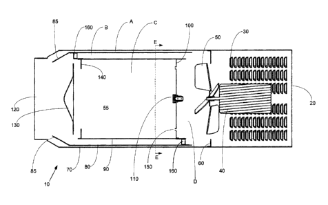
Figure 1 is a schematic illustrating an example of a direct-fired ductable
heater;
Figure 2 is a schematic cross-section along line E-E of Figure 1, illustrating
an
example of a pattern of openings of a burner plate for a direct-fired heater;
Figure 3 is a schematic illustrating another example of the pattern of
openings of
a burner plate for a direct-fired heater; and
Figure 4 is a schematic illustrating another example of the pattern of
openings of
a burner plate for a direct-fired heater.
DETAILED DESCRIPTION
Figure 1 is a schematic illustrating an example of a direct-fired heater
suitable for
use with ductwork. The heater is shown generally at 10. The heater 10 has an
outer shell 70 with an intake in one end allowing for the intake of air to be
heated
and an exhaust outlet 120 in the other end for allowing heated air to exit the
heater 10. An optional intake may also be used, for example in the form of
louvers 30 in the outer shell 70. Based on the amount of heat desired, the
intake
20 and optionally 30 may vary in size as desired.
-4-
CA 02638435 2008-07-31
A fan motor 40 is used to drive a fan blade 50 and is powered by any
conventional means.
A blower plate 60 is used to prevent or minimize recirculation of air past the
fan
blade 50. The clearance between the blower plate 60 and the fan blade 50 may
be small enough to stop the recirculation, thereby increasing the efficiency
of the
heater 10.
A combustion chamber 55 of the heater 10 is defined by a combustion chamber
wall 90, a bumer plate 100 at one end and an exhaust plate 140 at an opposite
end. Combustion takes place in what will be referred to for the purposes of
this
specification as a combustion zone C in the combustion chamber 55. The bumer
plate 100 has a series of openings 150 that allow for air to be pushed through
the
bumer plate 100 by the fan blade 50. Although only two openings 150 are
illustrated in Figure 1, any number of openings may be used to allow airflow
through the bumer plate 100 as will be disclosed in more detail below. The
space defined by the burner plate 100 and the fan blade 50 will be referred to
as
recirculation zone D for the purposes of this specification and will be
disclosed in
more detail further below. The exhaust plate 140 has one or more exhaust
openings therein allowing for exhausting of hot exhaust from the combustion
chamber 55. A gas injector 110 connected to the bumer plate 100 injects fuel
in
the form of gas, usually either natural gas or propane, into the combustion
chamber 55. The injected gas combines with air being pushed through the
burner plate 100.
A nose cone 130, positioned exterior the exhaust plate 140, directs exhaust
from
the combustion chamber 55 and out of the outlet 120. An optional heat shield
80
is situated between the combustion chamber wall 90 and the outer shell 70. An
air passage is defined by the gap between the heat shield 80 and the
combustion
chamber wall 90. For the purposes of this specification, this air gap will be
referred to as zone B. An additional air passage is defined by the gap between
the heat shield 80 and the outer shell 70. For the purposes of this
specification,
-5-
CA 02638435 2008-07-31
this air gap will be referred to as zone A. The heat shield 80 is shown as
being
connected to the combustion chamber wall 90 using a plurality of brackets 160.
It should be understood that any suitable connection device may be used to
secure the heat shield 80 in the heater 10. The heat shield 80 may
additionally
or alternatively be secured to the outer shell 70 using spacers or by any
suitable
connection device. As outlined above, any suitable device may be used to
secure the heat shield 80 to the combustion chamber wall 90 and/or the outer
shell 70, however, at least zone A or zone B must be maintained to allow for
airflow between the outlet 120 and recirculation zone D. In one embodiment, no
heat shield is used and a single airflow zone is defined by the space between
the
combustion chamber wall 90 and the outer shell 70.
As illustrated in Figure 1, the heat shield 80 comprises an optional deflector
segment 85 on the exhaust side of the heater. The deflector segment 85 guides
the airflow from zones A and B inwards increasing the rate at which the cooler
air
flowing though zones A and B mixes with the heated exhaust being exhausted
from the combustion chamber 55. The relative positioning of the deflector
segment 85, the nose cone 130, the combustion chamber wall 90, and the
exhaust plate 140 creates a venturi effect that increases the airflow
efficiency
through the combustion chamber 55. It should be understood that the deflector
segment 85 does not have to be integrated into the heat shield 80 but may be a
separate component shaped to help mix the cooler airflow of zones A and/or B
with the heated exhaust and also to create a venturi effect at the combustion
chamber 55 outlet. Further, the nose cone 130 may be flat, however, a conical
surface on the exhaust side of the nose cone 130 facilitates the creation of
the
venturi and reduces the pressure drop on air flowing through the heater 10.
The heat shield 80, in addition to both shielding the outer shell 70 from heat
and
defining airflow zone B, also serves to cool the combustion chamber wall 90 by
allowing for airflow propelled by the fan blade 50 to absorb heat as it passes
through zone B. By cooling the combustion chamber wall 90, the operational
-6-
CA 02638435 2008-07-31
lifetime of the combustion chamber wall 90 is increased as the higher
temperature causes increased fatigue on the material.
Typical heaters used in the art tend to increase the distance between the
bumer
plate 100 and the fan blade 50 in an attempt to minimize recirculation as
objects
placed in front and in proximity to the fan blade 50 deflect airflow back
towards
the fan, especially towards the center of the fan blade 50 where the pushing
effect of the fan blade 50 is lower. As a side effect, this results in a
physically
larger heater and also in the burner plate 100, the injector 110, and the gas
line
feeding the injector 110 having a very high temperature during operation.
Heaters 10 of the present invention, however, have a layout with the burner
plate
100 placed in close proximity to the fan blade 50, relative to conventional
heaters. The burner plate 100 is placed at a distance from the fan blade 50
suitably close to cause sufficient recirculation of the air in zone D to cool
the
injector 110 during operation. This recirculation increases the operational
lifetime
of the injector 110, the burner plate 100, and the gas line feeding the
injector.
As is understood in the art, an ideal air to gas mixture is desired to obtain
an
efficient combustion. Connection of ductwork to heaters, such as direct-fired
heaters, causes a variation in airflow due to the inherent backpressure caused
by
the connection of the ductwork. Airflow zones A and B are provided to reduce
fluctuations of airflow in the combustion chamber 55. As outlined above, a
single
airflow zone may be used if no heat shield is used.
Due to the shape of the fan blade 50 and its proximity to the outer shell 70
and
the burner plate 100, an inherent negative pressure field is generated
generally
in front of a center region of the fan blade 50 and a positive pressure field
is
generated generally in an outer region of the recirculation zone D. By
extending
the combustion chamber wall 90 and the heat shield 80 past the burner plate
100
and into the recirculation zone D, the pressure field increases and stabilizes
particularly near the outer edges of the bumer plate 100. It should be
understood
that although Figure 1 shows both the combustion chamber wall 90 and the heat
-7-
CA 02638435 2008-07-31
shield 80 extending into the recirculation zone D, it is not essential for
both of the
components to extend into the recirculation zone D. By providing for a
positive
pressure zone in the recirculation zone D using the airflow zones A and B, a
more consistent airflow in the combustion chamber 55 and in the combustion
zone C is observed thereby allowing for efficient combustion even when
ductwork is attached to the heater 10. Further the extension of the heat
shield 80
increases this positive pressure zone forcing a majority of the cooling air
around
the combustion chamber 55 through airflow zone B and maintaining minimum
enough cooling flow under the outer shell 70 through airflow zone A. Airflow
through zone A may be sufficient enough to keep the outer shell 70 at a
temperature touchable with an unprotected hand.
Figure 2 is a cross-section schematic taken along line E-E of Figure 1
illustrating
an example of a burner plate 100. The burner plate 100 contains a plurality of
microburners 200 comprised of one or more openings 150. An injector 110
generally in the center of the burner plate 100 is adapted to inject gas into
the
combustion chamber 55 (shown in Fig. 1) generally outward toward the
combustion chamber wall 90 and optionally perpendicular to the combustion
chamber wall 90. The gas is injected by the injector 110 in a plurality of gas
streams 210. The gas streams 210 and the microburners 200 may be oriented
so that each gas stream 210 directs a similar flow of gas at a corresponding
microburner 200 or set of microburners. As is illustrated in Figure 2, for
example,
each gas stream 210 is directed at a microburner 200 thereby resulting in a
substantially even burn. The microbumers 200 should have a spacing relative to
each other as well as a pattern of openings 150 that encourages a continuous
burn around the injector 110. Optionally, the pattem of openings 150 and
spacing of each microburner 200 may encourage a substantially symmetrical
burn around the injector 110. Furthermore, the openings 150 of the
microburners
200 may have an area corresponding to the flow of air generated by the
rotation
of the fan blade 50 as illustrated in Figure 2 to further create an even or
preferably symmetrical burn around the injector 110.
-8-
CA 02638435 2008-07-31
Although the injector 110 is shown having six gas streams 210, it should be
understood that the injector may emit any number of gas streams 210, with a
minimum of two gas streams required for a balanced flame.
A plurality of brackets 160 are shown connecting the heat shield 80 to the
combustion chamber wall 90, the heat shield 80 and the combustion chamber
wall 90 defining airflow zone B as outlined above. The brackets 160 are shown
in an angled orientation thereby guiding the airflow from the fan blade 50 in
a
spinning path. Alternatively, the brackets 160 may be oriented to straighten
out
airflow in zone B as desired.
Airflow zone A is shown defined by the heat shield 90 and the outer shell 70
as
outlined above. A spacer (not shown) may be used to connect the heat shield 80
and the outer shell 70.
As can be seen in Figure 2, the burner plate 100 has fewer openings 150
towards the center of the burner plate 100 and a higher density of openings
150
towards the outside of the bumer plate 100. This orientation may be used to
increase efficiency. As outlined above, a positive pressure zone is generated
towards the outside of the recirculation zone D and a negative pressure zone
is
generated towards the center of the recirculation zone D. To increase
circulation, and to minimize airflow differentiation when various lengths of
ductwork are attached to the heater 10, no openings 150 may be placed in the
burner plate 100 in the negative pressure region and a higher density of
openings may be placed in the positive pressure region. Such an orientation
also minimized and can even prevent gas mixture and/or flame from being
sucked into the recirculation zone D by the negative pressure.
The burner plate 100 with microburners 200, such as those described above,
forces the flame away from the injector 110 keeping the injector 110 at a
lower
temperature from the start. The microbumers 200 may be oriented in such a way
as to form a circle of multiple burners. The openings 150 of the microburners
200
may be oriented for example for balancing combustion air rotation with each
-9-
CA 02638435 2008-07-31
opening's dimension and position creating a staged combustion which can result
in low CO production and can further result in a primary recirculation for low
CO
and NOx generation.
The openings 150 may be extruded in the burner plate 100 in such a way that
the
perimeter of the opening 150 penetrates into the combustion chamber 55. This
results in an enlarged recirculation zone at the base of the flame between
openings 150, thereby reducing CO and NOx generation.
In one example, the increase in efficiency of the heater allowed for a
horsepower (hp) motor to be used in place of a 1 hp motor and a larger
diameter
fan blade 50 was used in place of a smaller diameter fan blade. This requires
less energy to drive the motor while maintaining heated air out of the outlet
120
and through any ductwork if attached. An increase in airflow through connected
ductwork has been observed. For example, a heater such as that described in
Figure 1, directed heated airflow through a duct 16 inches in diameter and 52
feet in length.
Figures 3 and 4 are an illustration of examples of a burner plate 100 showing
a
different arrangement for the openings 150 of the microburners 200. The
openings 150 include both holes and louvers. The louvers may be used to
maintain the spin of spinning air entering the combustion chamber 55. As with
the burner plate 100 shown with reference to Figure 2, the total surface area
of
the openings 150 closer to the center of the burner plate 100 is smaller than
the
total surface area of the openings 150 further away from the center of the
burner
plate 100 to minimize and even stop back flow of gas and/or flame past the
burner plate 100 toward the fan blade (not shown).
It will be appreciated that heaters as described herein may operate with or
without ductwork connected to the outlet of the heater. Furthermore, it will
be
appreciated that heaters of the present invention may comprise inlet gas
piping
and valving as desired or required for feeding gas to the injector from a gas
source.
-10-
CA 02638435 2008-07-31
The present invention has been described with regard to a plurality of
illustrative
embodiments. However, it will be apparent to persons skilled in the art that a
number of variations and modifications can be made without departing from the
scope of the invention as defined in the claims.
-11-