Sélection de la langue

Search

Sommaire du brevet 2643427 

Énoncé de désistement de responsabilité concernant l'information provenant de tiers

Une partie des informations de ce site Web a été fournie par des sources externes. Le gouvernement du Canada n'assume aucune responsabilité concernant la précision, l'actualité ou la fiabilité des informations fournies par les sources externes. Les utilisateurs qui désirent employer cette information devraient consulter directement la source des informations. Le contenu fourni par les sources externes n'est pas assujetti aux exigences sur les langues officielles, la protection des renseignements personnels et l'accessibilité.

Disponibilité de l'Abrégé et des Revendications

L'apparition de différences dans le texte et l'image des Revendications et de l'Abrégé dépend du moment auquel le document est publié. Les textes des Revendications et de l'Abrégé sont affichés :

  • lorsque la demande peut être examinée par le public;
  • lorsque le brevet est émis (délivrance).
(12) Demande de brevet: (11) CA 2643427
(54) Titre français: METHODE POUR COMMANDER UNE MACHINE DE MOULAGE PAR INJECTION DE TYPE MELANGEUR ET MACHINE DE MOULAGE PAR INJECTION DE TYPE MELANGEUR
(54) Titre anglais: METHOD OF CONTROLLING A COMPOUNDER-TYPE INJECTION MOLDING MACHINE, AND COMPOUNDER-TYPE INJECTION MOLDING MACHINE
Statut: Morte
Données bibliographiques
(51) Classification internationale des brevets (CIB):
  • B29C 45/76 (2006.01)
  • B29C 45/17 (2006.01)
(72) Inventeurs :
  • WOBBE, HANS (Allemagne)
(73) Titulaires :
  • KRAUSS-MAFFEI KUNSTSTOFFTECHNIK GMBH (Allemagne)
(71) Demandeurs :
  • KRAUSS-MAFFEI KUNSTSTOFFTECHNIK GMBH (Allemagne)
(74) Agent: FETHERSTONHAUGH & CO.
(74) Co-agent:
(45) Délivré:
(22) Date de dépôt: 2002-12-11
(41) Mise à la disponibilité du public: 2003-06-21
Requête d'examen: 2008-11-03
Licence disponible: S.O.
(25) Langue des documents déposés: Anglais

Traité de coopération en matière de brevets (PCT): Non

(30) Données de priorité de la demande:
Numéro de la demande Pays / territoire Date
101 63 409.9-51 Allemagne 2001-12-21

Abrégés

Abrégé anglais


In a method of controlling the feed amount of compounding materials for a
compounder-type injection molding machine with a plasticizing unit, an
injection
unit, receiving plasticized material from the plasticizing unit, and a
metering unit
for supply of starting material into the plasticizing unit, the volume of a
mass
stream downstream of the plasticizing unit is ascertained and the metering
unit is
operated in response to the ascertained volume.

Revendications

Note : Les revendications sont présentées dans la langue officielle dans laquelle elles ont été soumises.


CLAIMS
What is claimed is:

1. A method of controlling the feed amount of compounding materials for a
compounder-type injection molding with a plasticizing unit, an injection unit
receiving plasticized material from the plasticizing unit, and a metering unit

for supply of starting material into the plasticizing unit, said method
comprising the steps of ascertaining the volume of a mass stream
downstream of the plasticizing unit and operating the metering unit in
response to the ascertained volume.

2. The method of claim 1, wherein the operating step is implemented to
correspond the volume of the mass stream downstream of the plasticizing
unit to the volume of starting material introduced by the metering unit into
the plasticizing unit.

3. The method of claim 1, wherein the volume of the mass stream is
determined on the basis of at least one of a cycle time and stroke volume of
the injection unit.

4. The method of claim 1 for controlling a plurality of such metering units.
9


5. A method of regulating the feed amount of compounding materials for a
compounder-type injection molding with a plasticizing unit, an injection unit
receiving plasticized material from the plasticizing unit, and a metering unit
for supply of starting material into the plasticizing unit, said method
comprising the steps of ascertaining a pressure in a header of the
plasticizing unit; and operating the metering unit in response to the
ascertained pressure in the header.

6. The method of claim 5, wherein the metering unit issues a metered stream
which is changed inversely proportional to changes in pressure.

7. The method of claim 5 for controlling a plurality of such metering units.
8. A compounder-type injection molding machine, comprising:

a plasticizing unit;

at least one metering unit fluidly connected to the plasticizing unit for
supply
of material;

an injection unit receiving plasticized material from the plasticizing unit
for
injection of a mass stream into an injection mold; and

control means for ascertaining a volume of the mass stream downstream of
the plasticizing unit and operating the metering unit in response to the
ascertained volume.


9. The compounder-type injection molding machine of claim 8, wherein the
control means includes a flow volume measuring device disposed
downstream of the plasticizing unit for generating an output signal
representative of the volume of the mass stream, and a control unit receiving
the output signal for controlling the metering unit in response to the output
signal.

10. The compounder-type injection molding machine of claim 8, wherein the
control unit controls the metering unit to introduce a same volume of starting

material into the plasticizing unit as the volume of the mass stream
downstream of the plasticizing unit.

11. A compounder-type injection molding machine, comprising:
a plasticizing unit having a header;

at least one metering unit fluidly connected to the plasticizing unit for
supply
of material;

an injection unit receiving plasticized material from the plasticizing unit
for
injection of a mass stream into an injection mold; and

regulating means for ascertaining a pressure in the header of the plasticizing

unit and operating the metering unit in response to the ascertained pressure.
11

Description

Note : Les descriptions sont présentées dans la langue officielle dans laquelle elles ont été soumises.


CA 02643427 2008-11-03
31254-15D

METHOD OF CONTROLLING A COMPOUNDER-TYPE INJECTION
MOLDING MACHINE, AND COMPOUNDER-TYPE INJECTION
MOLDING MACHINE

CROSS-REFERENCE TO RELATED APPLICATION
5[0001] This application is a divisional application of
Canadian Patent Application No. 2,414,437 filed on
December 11, 2002.

BACKGROUND OF THE INVENTION

[0002] The present invention relates to a control or
regulating method for a compounder-type injection molding
machine.

[0003] Compounders are devices for fabricating plastic
articles and include essentially a plasticizing unit, which
accommodates a screw and receives compounding materials such

as plastic granulates, fiber materials and other compounding
materials from one or more metering units. These materials
are plasticized and advanced in longitudinal direction of
the plasticizing unit to a header, as the screw rotates, for
transfer to an injection unit in the form of a piston and

cylinder arrangement. The injection unit injects the
plasticized and

1


CA 02643427 2008-11-03

heated plastic material into a mold for producing the finished plastic
article.
[0004] The plastic granulates or like materials are typically fed via lateral
metering devices or feed hoppers to the plasticizing unit continuously or
intermittently or in dependence on the filling level of the plasticizing unit.
Hereby,
it may happen that depending on the operating conditions excessive, or
insufficient amounts of material are supplied. Moreover, the metered amounts
have to be readjusted, each time a new article is intended for production.

.. j

[0006] It would therefore be desirable and advantageous td provide an
improved method of controlling or regulating a compounder-type injection
molding machine, to obviate prior art shortcomings and to prevent supply of
incorrect amounts of materials, without requiring a readjustment, when
different
amounts are necessary upon an article change.

SUMMARY OF THE INVENTION
=, -
[00061 According to one aspect of the present invention, a method of

controlling the feed amount of compounding materials for a compounder-type
injection molding with a plasticizing unit, an injection unit receiving
plasticized
material from the plasticizing unit, and a metering unit for supply of
starting
material into the plasticizing unit, said method comprising the steps of
ascertaining the volume of a mass stream downstream of the plasticizing unit,
2


CA 02643427 2008-11-03

and operating the metering unit in response to the ascertained volume.

[00071 The present invention resolves prior art problems by proposing to
make the voiume amount of material to be introduced by the metering unit into
the plasticizing unit dependent on the volume downstream the plasticizing
unit,
i.e. to correspond the volume of starting material being introduced from the
metering unit into the plasticizing unit to the volumetric mass stream
discharged
downstream of the plasticizing unit.

.. .
[0008] According to another feature of the present invention, the volume of
the mass stream may be determined on t.hP basis of a cycle time and/or stroke
volume of the Injection unit. Short cycle times thus mean an increase in the
metered amount while long cycle times mean a decrease in the metered amount.
On the other hand, a great stroke volume is accompanied by an increase in the
metered amount, while a small stroke volume is accompanied by a decrease in
the metered amount.
.,. .

[0009] According to another aspect of the present invention, a method of
regulating the feed amount of compounding materials for a compounder-type
injection molding with a plasticizing unit, an injection unit receiving
plasticized
material from the plasticizing unit, and a metering unit for supply of
starting
material into the plasticizing unit, said method comprising the steps of
ascertaining a pressure in a header of the plasticizing unit, and operating
the
3


CA 02643427 2008-11-03

metering unit in response to the ascertained pressure in the header.

[0010] In this type of control system, the pressure in the header of the
plasticizing unit of the compounder is ascertained and used as command
variable for operating the metering unit. Excessive pressure in the header of
the
plasticizing unit indicates that too much compounding materials is supplied,
while
low pressure in the header of the plasticizing unit indicates that
insufficient
amount of compounding materials is supplied, In this way, the metered stream
of
the metering unit is changed inversely proportional to changes in pressure.

[0011] The novel and inventive method of the invention is also applicable
for simultaneous control of several metering units for supply of plastic
material to
the same plasticizing unit.

BRIEF DESCRIPTION OF THE DRAWING

[0012] Other features and advantages of the present invention will be
more readily apparent upon reading the following description of currently
preferred exemplified embodiments of the invention with reference to the
accompanying drawing, in which: '

10013] FIG. I is a schematic block diagram of a first embodiment of
a principal configuration of a method according to the present invention with
4


CA 02643427 2008-11-03

reference to a compounder-type injection molding machine;

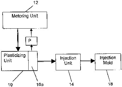
[0014] FIG. 2 is a schematic block diagram of a modified
arrangement for implementing the principal configuration of the method of FIG.
1;
and -
[00151 FIG, 3 is a schematic block diagram of a second
embodiment of a principal configuration of a method according to the present
invention with reference to a compounder-type injection molding machine.

DETAILED DESCRIPTION OF PREFERRED EMBODIMENTS

[0016] Throughout all the Figures, same or corresponding elements are
generally indicated by same reference numerals. These depicted embodiments
are to be understood as illustrative of the invention and not as limiting in
any way.
[0017] Turning now to the drawing, "and in particular to FIG. 1, there is
shown a schematic block diagram of a first embodiment of a principal
configuration of a method according to the present invention with reference to
a
compounder-type injection moldirig machine, including a plasticizing unit 10
which may be a twin screw extruder with screws rotating in opposite or same
directions, or a single screw extruder. Various materials can be introduced
into
the plasticizing unit 10 via one or more metering units 12. For example,
plastic


CA 02643427 2008-11-03

granulates may be supplied via one metering unit whereas fibers or other
additives may be supplied into the plasticizing unit 10 via another metering
unit.
Only one metering unit 12 is shown in FIG. 1 for the sake of simplicity. A
rotation
of the screw or screws in the plasticizing unit 10 results in a plastification
of the
material being introduced and advance thereof towards a header 10a (FIG. 2) of
the plasticizing unit 10 for transfer to an injection unit 14 configured in
the form of
a piston and cylinder arrangement, The injection unit 14 is in fluid
communication
via a passageway 16 with an injection mold 18 for molding the incoming
~ plasticized and heated plastic material to a finished plastic article.

[00181 Structure and mode of operation of compounder-type injection
molding machines are generally known to a person skilled in the art so that a
further description thereof is omitted for the sake of simplicity. A specific
construction and manner in which a compounder-type injection molding machine
of this type is typically operated is fully described in commonly assigned
copending patent application by a different inventive entity, entitled
"Compounder-type Injection Molding Machine", filed October 22, 2002, the
disclosure of which is incorporated herein by reference.

[0019] In accordance with the present invention, the compounder-type
injection molding machine includes a control unit 20 which receives an output
signal representative of the volume of the mass stream downstream of the
plasticizing unit 10 and operates the metering unit 12 in dependence on the
6


CA 02643427 2008-11-03

ascertained volume of the mass stream. Suitably, the volume of the mass stream
is ascertained as a function of the cycle time and/or the stroke volume of the
injection unit 14. Thus, when the injection unit 14 operates at short cycle
times,
the metered amount of starting material introduced by the metering unit 12
into
the plasticizing unit 10 is increased, while long cycle times mean a decrease
in
the metered amount. Conversely, a great stroke volume is accompanied by an
increase in the metered amount, while a small stroke volume is accompanied by
a decrease in the metered amount.

= J

[0020] FIG. 2 shows a schematic block diagram of a modified arrangement
for implementing the principal configuration of the method of FIG. 1. Parts
corresponding with those in FIG. 1 are denoted by identical reference numerals
and not explained again. In this modification, the volume of the mass stream
expelled from the injection unit 14 is determined by a flow volume measuring
device V which is disposed in the passageway 16 between the injection unit 14
and the injection mold 18 and generates an output signal representative of the
volume of the mass stream. The output sigttal is transmitted to the control
unit 20
for controlling the volume of material from the metering unit 12 to the
plasticizing
unit 10 to correspond to the ascertained volume of the mass stream through the
passageway 16.

[0021] Turning now to FIG. 3, there is shown a schematic block diagram of
a second embodiment of a principal configuration of a method according to the
7


CA 02643427 2008-11-03

present invention with reference to a compounder-type injection molding
machine. Parts corresponding with those in FIG_ I are denoted by identical
reference numerals and not explained again. The description below will center
on
the differences between the embodiments. In the embodiment of FtG. 3,
provision is made for a pressure measuring device P which ascertains the
pressure in header 10a of the plasticizing unit 10 to generate a command
variable for operating the metering unit 12.

[0022] While the invention has been illustrated and described in
connection with currently preferred embodiments shown and described in detail,
it is not intended to be limited to the details shown since various
modifications
and structural changes may be made without departing in any way from the
spirit
of the present invention. The embodiments were chosen and described in order
to best explain the principles of the invention and practical application to
thereby
enable a person skilled in the art to best utilize the invention and various
embodiments with various modifications as are suited to the particular use
contemplated.

[0023] What is claimed as new and desired to be protected by Letters
Patent is set forth in the appended claims and their equivalents:

8

Dessin représentatif
Une figure unique qui représente un dessin illustrant l'invention.
États administratifs

Pour une meilleure compréhension de l'état de la demande ou brevet qui figure sur cette page, la rubrique Mise en garde , et les descriptions de Brevet , États administratifs , Taxes périodiques et Historique des paiements devraient être consultées.

États administratifs

Titre Date
Date de délivrance prévu Non disponible
(22) Dépôt 2002-12-11
(41) Mise à la disponibilité du public 2003-06-21
Requête d'examen 2008-11-03
Demande morte 2010-12-13

Historique d'abandonnement

Date d'abandonnement Raison Reinstatement Date
2009-12-11 Taxe périodique sur la demande impayée

Historique des paiements

Type de taxes Anniversaire Échéance Montant payé Date payée
Requête d'examen 800,00 $ 2008-11-03
Enregistrement de documents 100,00 $ 2008-11-03
Le dépôt d'une demande de brevet 400,00 $ 2008-11-03
Taxe de maintien en état - Demande - nouvelle loi 2 2004-12-13 100,00 $ 2008-11-03
Taxe de maintien en état - Demande - nouvelle loi 3 2005-12-12 100,00 $ 2008-11-03
Taxe de maintien en état - Demande - nouvelle loi 4 2006-12-11 100,00 $ 2008-11-03
Taxe de maintien en état - Demande - nouvelle loi 5 2007-12-11 200,00 $ 2008-11-03
Taxe de maintien en état - Demande - nouvelle loi 6 2008-12-11 200,00 $ 2008-11-03
Titulaires au dossier

Les titulaires actuels et antérieures au dossier sont affichés en ordre alphabétique.

Titulaires actuels au dossier
KRAUSS-MAFFEI KUNSTSTOFFTECHNIK GMBH
Titulaires antérieures au dossier
WOBBE, HANS
Les propriétaires antérieurs qui ne figurent pas dans la liste des « Propriétaires au dossier » apparaîtront dans d'autres documents au dossier.
Documents

Pour visionner les fichiers sélectionnés, entrer le code reCAPTCHA :


Pour visualiser une image, cliquer sur un lien dans la colonne description du document. Pour télécharger l'image (les images), cliquer l'une ou plusieurs cases à cocher dans la première colonne et ensuite cliquer sur le bouton "Télécharger sélection en format PDF (archive Zip)" ou le bouton "Télécharger sélection (en un fichier PDF fusionné)".

Liste des documents de brevet publiés et non publiés sur la BDBC .

Si vous avez des difficultés à accéder au contenu, veuillez communiquer avec le Centre de services à la clientèle au 1-866-997-1936, ou envoyer un courriel au Centre de service à la clientèle de l'OPIC.


Description du
Document 
Date
(yyyy-mm-dd) 
Nombre de pages   Taille de l'image (Ko) 
Page couverture 2009-02-02 2 37
Revendications 2008-11-04 3 89
Description 2008-11-04 9 285
Abrégé 2008-11-03 1 14
Description 2008-11-03 8 272
Revendications 2008-11-03 3 85
Dessins 2008-11-03 3 21
Dessins représentatifs 2009-01-12 1 5
Correspondance 2009-02-06 1 17
Cession 2008-12-30 1 49
Correspondance 2008-12-30 2 145
Correspondance 2008-12-05 1 38
Cession 2008-11-03 2 90
Poursuite-Amendment 2008-11-03 6 172